

Page 1
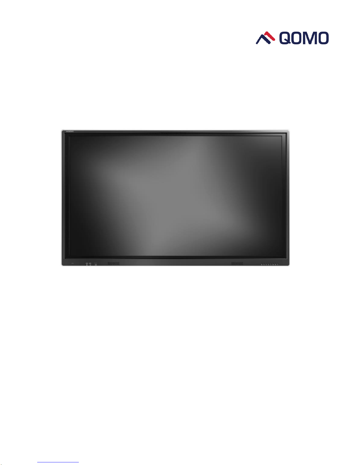
Interactive Touch Screen
User Manual
www.qomo.com
Page 2

Content
Safety Instruction ......................................................................................................................................... 1
Installation .................................................................................................................................................... 3
Bearing ................................................................................................ ................................................................................. 3
Wall-mounting ................................................................................................................................................................... 3
OPS Installation ................................................................................................................................................................. 4
Basic Operation ............................................................................................................................................ 5
Power on .............................................................................................................................................................................. 5
Power off ............................................................................................................................................................................. 5
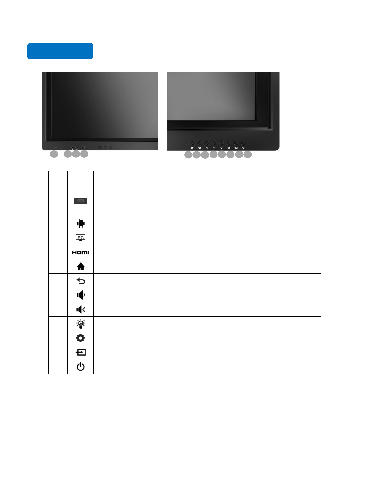
Control Panel ................................................................................................................................................ 6
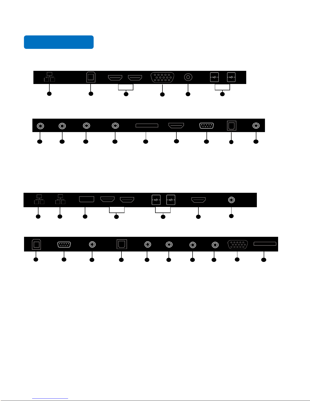
Terminal Interface ....................................................................................................................................... 7
Terminal Interface Type 1 ............................................................................................................................................... 7
Terminal Interface Type 2 ............................................................................................................................................... 7
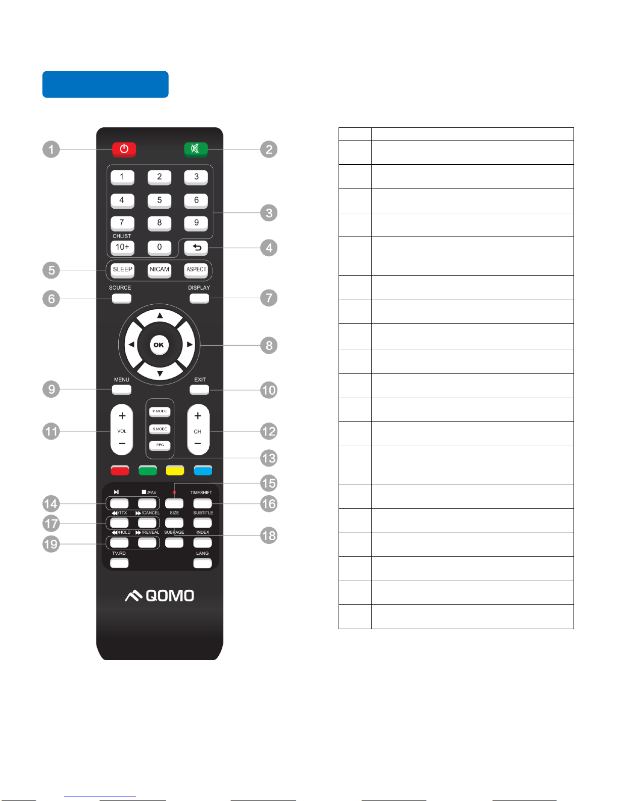
Remote Control ............................................................................................................................................ 8
Remote Control Area ....................................................................................................................................................... 9
Connecting and Setting .............................................................................................................................. 10
External Computer and Touch Connecting.............................................................................................................. 10
AV Connecting ................................................................................................................................................................. 11
Video-OUT ....................................................................................................................................................................... 12
RS232 ................................................................................................................................................................................. 13
Android Home Page ................................................................................................................................... 18
Education Version ........................................................................................................................................................... 18
Business Version ............................................................................................................................................................. 19
Bottom-up Toolbar ..................................................................................................................................... 20
Signal Source Selection .............................................................................................................................. 21
Android Settings ......................................................................................................................................... 22
Built-in PC Operation ................................................................................................................................ 26
Menu ............................................................................................................................................................ 27
Annotation software - MagicBoard .......................................................................................................... 28
Included Accessories .................................................................................................................................. 32
Troubleshooting .......................................................................................................................................... 33
Page 3

1
Safety Instruction
For your safety, please read the following instruction before you use the product. Serious injury or property loss
may be caused by improper operations. Do not try to repair the product without guidance.
Placement
Do not place the unit on an unstable cart, stand, tripod, racket, table, or shelf.
Do not expose the unit to direct sunlight and other sources of heat.
Do not handle liquids near or on the unit.
Never spill liquid of any kind into the unit
Do not put the unit near appliances that create magnetic fields.
Power Supply
Check that the unit’s operating voltage is identical with your local power supply.
Please unplug power supply and aerial plug when the weather is thunder-storm or lighting.
Please unplug power supply when there is nobody at home or didn’t use over a long time.
Please keep power cord from physical or mechanical damage.
Please use exclusive power cord, don't modify or lengthen it.
Please check and ensure AC source is connected with the ground.
A sudden power failure may damage the panel.
Frequent power on and off in a short time may cause faults.
LED Screen
Never use any other tough or sharp object to replace the written pen.
Unplug the power supply plug before cleaning.
Clean the screen with a soft dustless and dry cloth.
Never use water or the spray type detergent to clean the unit.
For deep clean, contact an authorized service center.
Please don’t display the high brightness image on the screen for a long time.
Sight Distance
The best distance between audience and screen is 5-7 times that of screen diagonal.
The best watching angle between audience and screen is within 176 degrees.
Temperature
Do not place the unit near or over a radiator or a heater register.
If your unit is suddenly moved from a cold to a warm place, unplug the power cord for at least.
Two hours so that moisture that may have formed inside the unit can dry completely.
Normal operating temperature is 5 ~ 40℃.
Page 4

2
Humidity
Do not expose machine in rain, damp or place near water.
Ensure the indoor drying, cool.
Ventilation
Keep the ventilation openings clear.
Ensure that the unit has enough space for ventilation around: left, right and back >10cm, top> 20cm.
Earphone
It will affect the hearing if you listen to noisy sound for a long time.
Before using earphone, please turn down the volume in advance.
CAUTION
This is a Class A product. In a domestic environment, this product may cause radio interference in which case
the user may be required to take adequate measures.
Page 5
3
Installation
Bearing
If the product is installed in a wall-mounted way, the bearing capacity of the surface for installation must be at least
four times of the weight of the product. If the surface for installation is a wall or the ceiling of a building, the
surface must be made of solid bricks, concrete or other materials with equal intensity. If the product is installed on
a surface made of loose material such as an old brick wall, wood plank wall, solid brick wall, a metal or non-metal
structure surface, or a surface with a thick decoration layer, take necessary consolidating measures to ensure that
the product is stably installed.
Note: When the product is installed in a wall-mounted way, the screws need to be installed deeper than 10 mm
in the wall. Do not block ventilation vents.
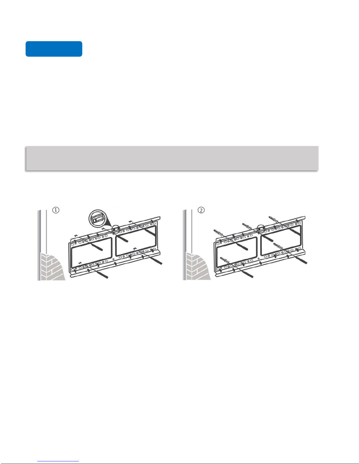
Wall-mounting
Use a level to locate the holes in a horizontal
line and mark with pencil where the holes will
be located. Then drill holes in the wall.
Level
Insert wall plugs into the mounting holes.
Push the self-tapping screws through the
bracket into the wall plugs and tighten the
screws.
Page 6
4
Note: The horizontal and vertical distance of mounting holes on the back of screen must be within
the required distance of bracket.
OPS Installation
Note: The OPS does not support hot-plugging. Please insert the plug of the OPS after the interactive
panel is disconnected from the power.
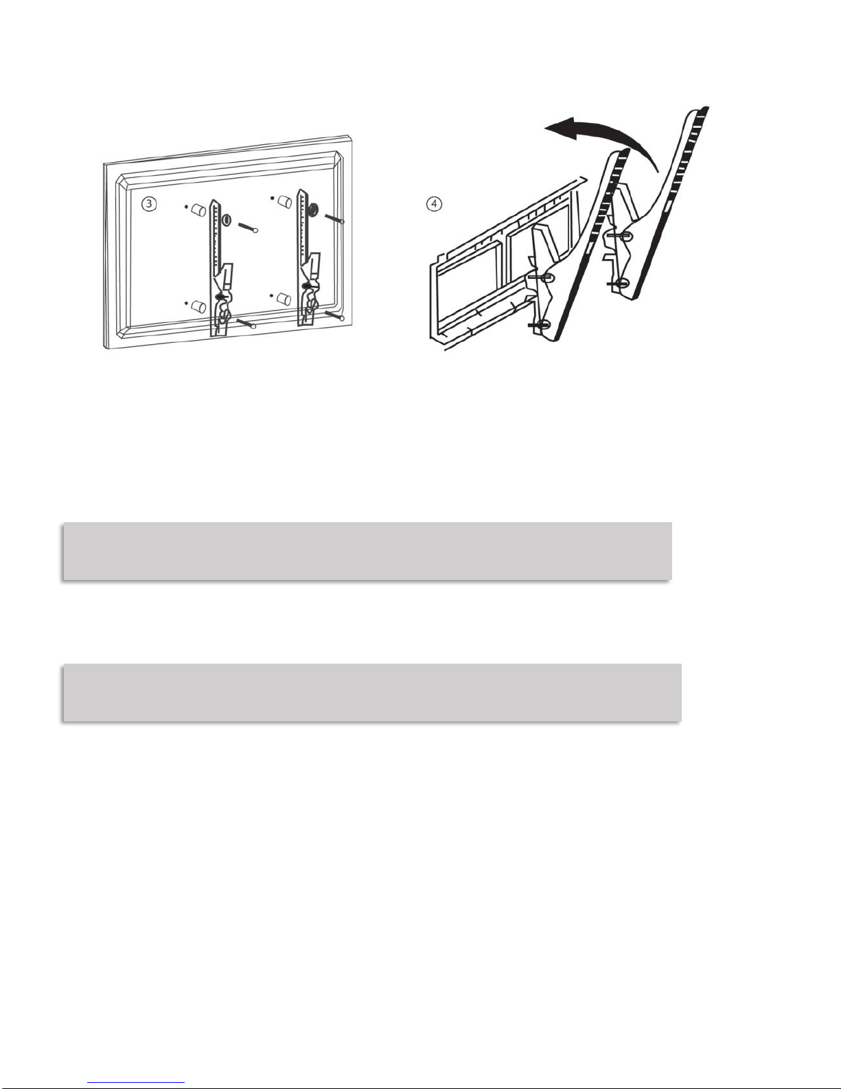
Install the OPS by the following steps:
1. Insert the OPS into the special slot on the rear of the interactive panel.
2. Tighten the screws.
3. Confirm that the OPS is installed correctly.
Attach the mounting arms to the
back of screen with the screws.
Insert wall plugs into the mounting holes.
Push the self-tapping screws through the
bracket into the wall plugs and tighten the
screws.
Page 7
5
Basic Operation
Power on
Power the interactive touch screen with the 100V-240V 50Hz/60Hz AC power supply.
Connect the panel to the power supply. Press the rocker switch (on the bottom left in the rear of the panel)
to enter standby mode. The power indicator turns red.
Press power button on the control panel or Power button on the remote control to turn on the display and
built-in PC simultaneously. The power indicator turns green.
Power off
Press ECO on the control panel to temporarily turn off the display.
Press power button on the control panel or Power button on the remote control to enter standby mode. The
power indicator turns red.
In standby mode, press the rocker switch to power off the touch screen.
Handle facing outward
Page 8
6
Control Panel
00
Item
Icon
Function Description
1
Power indicator:
Press power button on the control panel. The power indicator turns green.
Press power button on the control panel to enter the standby mode. The power
indicator turns red.
2 Android USB port
3 Built-in PC USB port
4 HDMI port used to connect an external display device
5 Enter/Return to Android home page
6 Return to previous interface
7 Decrease volume
8 Increase volume
9 Enter ECO mode to turn off the display
10 Enter/Exit Setting menu
11 Enter/Exit signal source menu
12 Power button: On or standby mode
1 2 3 4 5 6 7 8 9
10
11
12
Page 9
7
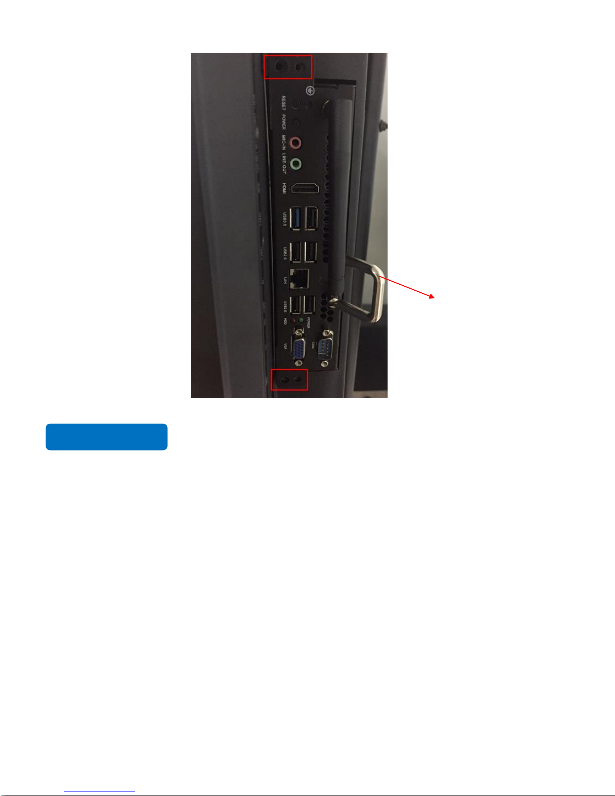
Terminal Interface
Terminal Interface Type 1
Terminal Interface Type 2
RJ45 IN USB-Touch HDMI IN VGA IN Audio IN USB 3.0
AV IN YPbPr IN AV OUT Earphone OUT SD CARD HDMI OUT RS232 SPDIF WIFI: antenna port
RJ45 IN RJ45 OUT DP IN HDMI IN USB 3.0 HDMI OUT WIFI: antenna port
USB-Touch RS232 Earphone OUT SPDIF IN YPBPR IN AV IN AV OUT Audio IN VGA IN SD Card
Page 10
8
Remote Control
Item
Function Description
1
Power on or standby mode
2
Mute on/off
3
Change channels or enter numbers
4
Return to previous interface
5
SLEEP: Set the sleep time
NICAM: Nicam button
ASPECT: Adjust picture aspect ratio
6
Signal source selection
7
Show the current signal source
8
Up/down/right/left direction buttons
OK: Confirm
9
Show or hide menu
10
Quit the current interface
11
Increase/decrease volume
`12
Change channel
13
P. MODE: Picture mode
SMODE: Sound mode
EPG: Digital Program Guide
14
Play/ Pause
15
Capture
16
Rewind or replay certain scenes
17
Fast forward/Rewind
18
Freeze the current screen
19
Previous/Next
Page 11
9
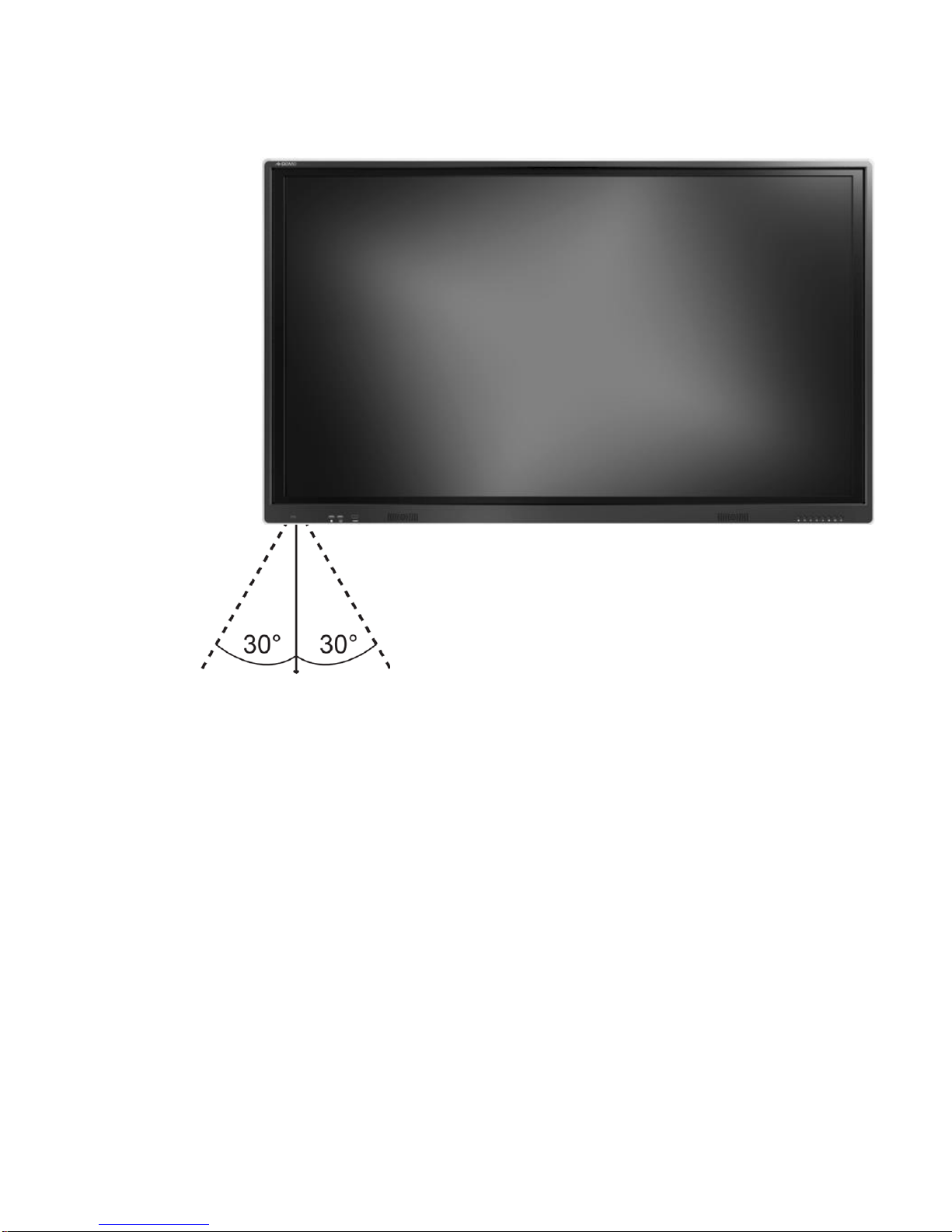
Remote Control Area
The effective receiving area is about 3 meters with 30° angle from vertical point to the left and right. And the
effective receiving area is about 5 meters from the front of device. Note that the remote control signal receiver
locates at the position of power indicator.
5M
Page 12

10
Connecting and Setting
For safety, please do not connect any power supply before the external devices setup.
1. External Computer and Touch Connecting
1) Connect a VGA cable (15 pin) between the VGA and external PC. Connect an earphone cable between the
PC and audio at the same time.
2) Connect a USB cable between the external PC and USB terminal.
3) Plug the POWER cord and switch it on from the rear panel.
4) Start up the external computer.
5) Press to turn on the panel.
6) Select Signal source to VGA source according to the one you connected.
Note: The panel can connect with the external PC via HDMI.
Audio IN VGA IN USB-Touch
Page 13

11
2. AV Connecting
AV IN
1) Connect an AV cable with the device with AV-OUT (Yellow is Video, Red is Audio-R, White is Audio-L).
2) Plug the POWER cord and switch it on from the rear panel.
3) Press to turn on the panel.
4) Select Signal source to AV IN source.
YPbPr
1) Connect a YPbPr cable with the device with YPbPr.
2) Plug the POWER cord and switch it on from the rear panel.
3) Press to turn on the panel.
4) Select Signal source to YPbPr source.
Page 14

12
Front HDMI/ HDMI 1/ HDMI 2
1) Connect a HDMI cable with the device with HDMI.
2) Plug the POWER cord and switch it on from the rear panel.
3) Press to turn on the panel.
4) Select Signal source to HDMI source according to the one you connected.
3. Video-OUT
HDMI-out
1) Connect a HDMI cable with the device with HDMI.
2) Plug the POWER cord and switch it on from the rear panel.
3) Press to turn on the panel.
Page 15

13
AV -OUT
1) Connect an AV cable with the device.
2) Plug the POWER cord and switch it on from the rear panel.
3) Press to turn on the panel. AV -OUT outputs the picture and sound of AV source.
4. RS232
1) Connect a serial port cable with the device.
2) Plug the POWER cord and switch it on from the rear panel.
3) After connecting the central control system and unit, you can use some of the function such as power on/off
or adjust the volume etc.
Page 16

14
RS232 code list
There are two RS232 code lists. Please check your Android firmware version first and refer to corresponding list
according to your Android firmware version.
RS232 Code for Android Firmware QOMO_xxx_xxx_xxxxx_Vxx
6 bytes command Baud rate: 115200 Data bits: 8 Check bit: none
Start code 99, Customer code (Public Version: XX = 23), Function ID code, Device ID code(It is generally
01, unless otherwise noted), Check code + Function ID code = FF, End code AA.
HOME
|99 XX 00 01 FF AA
Power Off
|99 XX 01 01 FE AA
Power On
|99 XX 80 01 7F AA
Mute
|99 XX 02 01 FD AA
Sound Mode
|99 XX 03 01 FC AA
Image Mode
|99 XX 04 01 FB AA
ATV
|99 XX 07 01 F8 AA
DTV
|99 XX 05 01 FA AA
Video
|99 XX 08 01 F7 AA
Component
|99 XX 0A 01 F5 AA
Computer 1
|99 XX 0B 01 F4 AA
Computer 2
|99 XX 0C 01 F3 AA
Computer 3
|99 XX 0D 01 F2 AA
Computer 4
|99 XX 06 01 F9 AA
HDMI1
|99 XX 0E 01 F1 AA
HDMI2
|99 XX 0F 01 F0 AA
Front Computer
|99 XX 10 01 EF AA
Built-in Computer
|99 XX 11 01 EE AA
DP
|99 XX 09 01 F6 AA
Menu
|99 XX 12 01 ED AA
Signal Source
|99 XX 13 01 EC AA
Exit
|99 XX 14 01 EB AA
Listen only audio
|99 XX 15 01 EA AA
Volume +
|99 XX 17 01 E8 AA
Volume -
|99 XX 18 01 E7 AA
Channel +
|99 XX 19 01 E6 AA
Page 17

15
Channel -
|99 XX 1A 01 E5 AA
Screenshot
|99 XX 1B 01 E4 AA
Screen Display
|99 XX 1C 01 E3 AA
Display ratio
|99 XX 1E 01 E1 AA
Sleep Mode
|99 XX 1D 01 E2 AA
Auto Adjustment
|99 XX 1F 01 E0 AA
Up
|99 XX 22 01 DD AA
Down
|99 XX 23 01 DC AA
Left
|99 XX 24 01 DB AA
Right
|99 XX 25 01 DA AA
Confirm
|99 XX 26 01 D9 AA
Multi-media
|99 XX 27 01 D8 AA
Device Status Query
|99 XX 28 01 D7 AA
1. Status Query Feedback 8 byte data
Start code 99, Board card model, Power On, Current channel, Volume, Sound mode, Check code (Current
channel + Volume + Sound mode), End code AA
1. Boar card model 01
2. Power on: 01
3. Current channel:
Computer 1 = 0B, Computer 2 = 0C, Computer 3 = 0D, Computer 4 = 06, ATV = 07, DTV = 05, Video
= 08, Aberration = 0A, HDMI1 = 0E, HDMI2 = 0F, DP= 09, Front computer = 10, Built-in computer =
11, Multi-media or Application state of third party = 0E
4. Volume: 0~100 (decimal) = 0~64 (hexadecimal),mute state = 65
5. Sound mode :Standard = 01, Music = 02, Movie = 03, Sports = 04,
User = 05, Immersive 1 = 06, Immersive 2 = 07
E.g.:99 01 01 0C 32 03 41 AA
Note: Power off state without any feedback.
RS232 Code for Android Firmware QOMO_xxx_xxxx_Rxx
RS232 Setting: Baud rate: 115200 bps; Parity check: no parity; Stop bit: one; Data bit: 8 bits;
RS232 Packet 1
(Packet size : 8
bytes)
0 1 2 3 4 5 6 7 Header 1
Header 2
Header 3
CMD1
CMD2
Data 1
Data 2
Data 3
0x55
0x54
0x53
0xXX
0xXX
0xXX
0xXX
0xXX
Command List
Function
Header 1
Header 2
Header 3
CMD1
CMD2
Data 1
Data 2
Data 3
Start Panel
remotely
0x55
0x54
0x53
0x50
0x4E
0x21
0x21
0x21
Shutdown panel
remotely
0x55
0x54
0x53
0x50
0x46
0x21
0x21
0x21
Get Signal Source
0x55
0x54
0x53
0x50
0x53
0x21
0x21
0x21
Page 18

16
(Bidirectional)
Set Signal Source
(DTV)
0x55
0x54
0x53
0x50
0x73
0x21
0x21
0x21
Set Signal Source
(ATV)
0x55
0x54
0x53
0x50
0x73
0x21
0x21
0x21
Set Signal Source
(Video 1)
0x55
0x54
0x53
0x50
0x73
0x30
0x30
0x21
Set Signal Source
(Video 2)
0x55
0x54
0x53
0x50
0x73
0x30
0x31
0x21
Set Signal Source
(Component)
0x55
0x54
0x53
0x50
0x73
0x30
0x32
0x21
Set Signal Source
(HDMI 1)
0x55
0x54
0x53
0x50
0x73
0x30
0x33
0x21
Set Signal Source
(HDMI 2)
0x55
0x54
0x53
0x50
0x73
0x30
0x34
0x21
Set Signal Source
(PC1)
0x55
0x54
0x53
0x50
0x73
0x30
0x35
0x21
Set Signal Source
(PC2)
0x55
0x54
0x53
0x50
0x73
0x30
0x36
0x21
Set Signal Source
(S terminal)
0x55
0x54
0x53
0x50
0x73
0x30
0x37
0x21
Set Signal Source
(Built-in HDMI)
0x55
0x54
0x53
0x50
0x73
0x30
0x38
0x21
Set Signal Source
(External HDMI)
0x55
0x54
0x53
0x50
0x73
0x30
0x39
0x21
Get Display Mode
(Bidirectional)
0x55
0x54
0x53
0x50
0x44
0x31
0x30
0x21
Set Display Mode
(16:9)
0x55
0x54
0x53
0x50
0x64
0x31
0x31
0x21
Set Display Mode
(4:3)
0x55
0x54
0x53
0x50
0x64
0x21
0x21
0x21
Set Display Mode
(Figure Mode)
0x55
0x54
0x53
0x50
0x64
0x30
0x21
0x21
Set Display Mode
(Full View Mode)
0x55
0x54
0x53
0x50
0x64
0x31
0x21
0x21
Set Display Mode
(Subtitle Mode)
0x55
0x54
0x53
0x50
0x64
0x32
0x21
0x21
Set Display Mode
(Movie Mode)
0x55
0x54
0x53
0x50
0x64
0x33
0x21
0x21
Get Display Mode
(Bidirectional)
0x55
0x54
0x53
0x50
0x50
0x34
0x21
0x21
Set Image Mode
(Standard)
0x55
0x54
0x53
0x50
0x70
0x35
0x21
0x21
Set Image Mode
(Bright)
0x55
0x54
0x53
0x50
0x70
0x21
0x21
0x21
Set Image Mode
(Soft)
0x55
0x54
0x53
0x50
0x70
0x30
0x21
0x21
Set Image Mode
(Customized)
0x55
0x54
0x53
0x50
0x70
0x31
0x21
0x21
Get Sound Mode
0x55
0x54
0x53
0x50
0x41
0x32
0x21
0x21
Page 19

17
(Bidirectional)
Set Sound Mode
(Standard)
0x55
0x54
0x53
0x50
0x61
0x33
0x21
0x21
Set Sound Mode
(Music)
0x55
0x54
0x53
0x50
0x61
0x21
0x21
0x21
Set Sound Mode
(News)
0x55
0x54
0x53
0x50
0x61
0x30
0x21
0x21
Set Sound Mode
(Movie)
0x55
0x54
0x53
0x50
0x61
0x31
0x21
0x21
Set Sound Mode
(Customized)
0x55
0x54
0x53
0x50
0x61
0x32
0x21
0x21
Get Volume
(Bidirectional)
0x55
0x54
0x53
0x50
0x56
0x33
0x21
0x21
Set Volume
(000-100)
0x55
0x54
0x53
0x50
0x76
0x34
0x21
0x30~
0x39
Get Channel
(Bidirectional)
0x55
0x54
0x53
0x50
0x43
0x21
0x21
0x21
Set Channel
(000-999)
0x55
0x54
0x53
0x50
0x63
0x30~
0x31
0x30~
0x39
0x30~
0x39
Screen brighten
0x55
0x54
0x53
0x50
0x42
0x21
0x21
0x21
Screen darken
0x55
0x54
0x53
0x50
0x62
0x30~
0x39
0x30~
0x39
0x21
Mute
0x55
0x54
0x53
0x50
0x4D
0x21
0x21
0x21
Channel+
0x55
0x54
0x53
0x50
0x3E
0x21
0x21
0x21
Channel-
0x55
0x54
0x53
0x50
0x3C
0x21
0x21
0x21
Volume+
0x55
0x54
0x53
0x50
0x2B
0x21
0x21
0x21
Volume-
0x55
0x54
0x53
0x50
0x2D
0x21
0x21
0x21
Menu
0x55
0x54
0x53
0x50
0x6D
0x21
0x21
0x21
Signal Source
0x55
0x54
0x53
0x50
0x58
0x21
0x21
0x21
Up (keyboard)
0x55
0x54
0x53
0x50
0x55
0x21
0x21
0x21
Down (keyboard)
0x55
0x54
0x53
0x50
0x44
0x21
0x21
0x21
Left (keyboard)
0x55
0x54
0x53
0x50
0x4C
0x21
0x21
0x21
Right (keyboard)
0x55
0x54
0x53
0x50
0x52
0x21
0x21
0x21
Ok (Keyboard)
0x55
0x54
0x53
0x50
0x4F
0x21
0x21
0x21
Back Button
0x55
0x54
0x53
0x50
0x45
0x21
0x21
0x21
Home button
0x55
0x54
0x53
0x50
0x48
0x21
0x21
0x21
Page 20

18
Android Home Page
Education Version
Android home page consists of three parts as shown in above picture. Click on the toolbar or Press HOME
button to enter the home page.
1. Click a signal source in part ① and its preview will be shown in part ②. Then click part ② to enter its
corresponding signal source.
2. Part ③ includes four icons Settings, Chrome Browser, Applications and File Explorer. Click the icon to
enter its corresponding interface.
Settings: Click the icon to enter the Android settings interface.
Browser: Built-in browser.
Applications: Click the icon to access more applications interface.
Explorer: Click the icon to manage.
1 2 3
Page 21

19
Business Version
Android home page mainly contains three parts: Quick-access Apks, Time and Network Connection Status.
Click on the toolbar or Press HOME button to enter the home page.
1. Click to open corresponding APK; Click to display all the APKs installed.
2. Long press to customize quick-access APK. When you long press the icon, it turns from static to dynamic.
APKS installed will appear and then select one to set as a Quick-access APK. Note that Applications cannot be
replaced or removed.
3. Click or icon to directly enter its setting interface.
4. Swipe the screen from left to right to bring out Search interface. Search history can be recorded or cleared.
Click search history and you will quickly visit the link again.
Page 22

20
Bottom-up Toolbar
The toolbar can be invoked in any signal source interface. Swipe up from the bottom of screen and it will appear.
Buttons
Functions
PC
Click to enter PC source
Back
Return to previous interface
Home
Return to Android home page
Task
Switch or end the running programs
Input
Change signal source channel
Setting
Click to enter setting interface
Volume
Slide to increase or decrease the volume
Light
Slide to increase or decrease the brightness
Capture
Take a screenshot and automatically save it
Lock
Click to lock the screen
Note
Quick to annotate
Page 23

21
Signal Source Selection
There are three ways to select a signal source to display.
Swipe your finger up from the bottom edge to bring up a toolbar then click Input.
Press SOURCE button on the remote control.
Press button on the front control panel.
Default Signal Source Interface
Click “…” to display all the sources
In the signal source page, select a channel and press OK or click the channel icon directly to enter it.
Page 24

22
Android Settings
Click setting icon on home page to enter Android setting interface.
1. Common function: Click Common function to set Starting Channel, Sound, Wallpaper, ECO, Lock Screen and
Factory Data Reset.
Starting Channel: Start the Panel and enter the channel you set directly.
Sound: Click Sound and the icon pops up. Slide right or left to increase or decrease
the volume.
Wallpaper: Set dynamic or static wallpaper.
ECO: Set the time to enter ECO mode automatically.
Lock Screen: Set the time to lock screen automatically and password to unlock the screen.
Factory data reset: Click Factory data reset and then click Reset TV to erase all the data on TV.
Page 25

23
2. Network and equipment: Click Network and equipment to set WLAN, Ethernet, Tethering& portable hotspot
and Mcast.
WLAN: Select an available wireless network AP and enter the password to be connected. Click and a
menu pops up. Select “Advanced” for further setting.
Ethernet: If the panel is connected with LAN cable and supports Dynamic Host Configuration Protocol
(DHCP), the system will automatically configure the internet protocol (IP) value; If the network protocol
needs to be set manually, enter the IP address, Gateway and DNS server parameters by using the on-screen
keyboard or remote control.
Tethering & portable hotspot: Enable Portable WLAN hotspot function to set the panel as a wifi hotspot.
3. Storage/ Apps: Click Storage to check internal storage and USB storage. Click StorageApps or Apps to
check and manage the applications installed in Android system. You can force to stop a program or uninstall it.
Note: You cannot uninstall app pre-installed in the firmware.
Page 26

24
4. Language & input: Where you can change the system or keyboard language.
Page 27

25
5. Date & time: Where you can change time format, time zone and etc.
6. About: Click About to check network status, model, Android version, Kernel version and etc. Click Status and
enter its page to get the Mac address.
Page 28

26
Built-in PC Operation
1. Select PC signal source to enter PC interface. The following are three ways to select a signal source channel.
Swipe your finger up from the bottom edge to bring up a toolbar then click input.
Press SOURCE button on the remote control.
Press button on the front control panel.
In the signal source page, select a channel and press OK or click the channel icon directly to enter it.
2. Operate the built-in PC in the same way as you operate an ordinary computer.
3. Shut down PC before you turn off the panel. Do not power off a running PC suddenly to avoid data lose. Or you
could also press Power button to turn off PC and panel at the same time.
Page 29

27
Menu
When you switch to other signal sources like OPS, HDMI, VGA and etc, settings interface will be displayed as
follows: Picture, Sound and Setting. Note that TV setting is disabled.
Click an icon to set the option or press button on remote control to switch the options.
Press▲/▼ button to select.
Press OK button to confirm the selection.
Press menu button to return to the parent menu.
Press EXIT button to quit.
Page 30

28
Annotation software - MagicBoard
MagicBoard provides various functions like annotation, capture, quick-access Apps & Docs and etc.
Click icon to enter whiteboard interface. And click icon to fold/unfold the toolbar.
MagicBoard Interface
Icons
Functions
Click to exit the program or Select to keep it running in the
background
Click “<” or “>” to switch current slide and click page
number to skim through all slides or quickly switch to a
certain slide.
Pen
Erase the annotations
Undo/Redo
Background color
Fold/unfold the toolbar
Add a new slide
Rectangular selection
Add a text (Check “Marquee” box to create a scrolling text.)
Save file
Quick access files
Page 31

29
1. Save file: Click icon to save the file.
Check “Save to editable file” box so that you can reedit this file next time. You can open this editable file
through DOC of File Management .
You have the option to save the file in PDF format and scan QR code to share the file. Note that you mobile
device should be in the same network with Magicboard.
2. File management: Skim through files in SD card or USB flash drive. View image, video, music, documents and
all the Apps installed.
Click corresponding App icon to open the App.
Click “Doc”, long press the file and you can rename or delete the file.
Page 32

30
3. Whiteboard running in the background: Click icon then click “Background” and the whiteboard will run
in the background.
Icon will appear on both sides. Click either of them to unfold the tools. Note that floating icons will float in every
singal source for annotation.
Floating Tool Bar
Buttons
Functions
Return to previous interface
Return to the Android Home Page
Quick access files
Page 33

31
Annotation mode
Save annotation as an image or scan QR code
to share the annotation
Enter the whiteboard
Rectangular screenshot
Window Shade
Adjust volume
Page 34

32
0
Included Accessories
Picture
Name
Quantity
Remote control
*1
Battery (AAA)
*2
Pen
*2
Pointer
*1
1.8m power cable
*1
3m HDMI cable
*1
3m USB cable (A-B)
*1 Bracket
*1
Antenna sticks for PC and
Android
*2
Warranty card
*1
CD
*1
Page 35

33
Troubleshooting
Remote Control
Remote control out of order
Check whether there is object between remote control and panel
receiver;
Check whether the battery is installed correctly;
Check whether the battery is drained.
Touch
Touch does not response.
Make sure infrared frames have not been obscured.
Check whether you enable freeze function on remote control.
Built-in PC
OPS shut down automatically.
Check if OPS is properly installed;
Sleeping mode setting;
Handwriting
Part of the handwriting cannot
be displayed.
Use the pen rather than a finger to write. Hold the pen as far to
the nib as possible. The angle between the pen and display needs
to be greater than 60 degrees. Do not touch the display with your
sleeve or wrist.
Change the nib or use a pen with larger covering area.
Check if infrared frames are obscured.
Remove the interference source or change the using environment.
No display or no sound
No sound is played and no
image is displayed.
Check whether the power plug is inserted into the power socket
and whether the panel is powered on.
Check whether the rocker switch on the interactive panel is
switched on.
Check whether panel is in ECO mode.
Check whether the video and audio input cables are connected
correctly.
Check whether the panel is switched to the right signal source.
Check the settings on image brightness and contrast.
Check the volume.
Image is displayed properly, but
no sound is played.
Check the volume.
Check whether the Mute button on the remote control is pressed.
Check whether the audio cable between the PC and interactive
panel is connected correctly.
No image is displayed or the
image is black and white.
Modify the color settings.
Check the color system.
This is the general user manual for all QOMO interactive touch screens. Some details may be different from the
actual product.
 Loading...