

Page 1

USER MANUAL
Pure Sine Wave Solar Inverter
MODEL: 53890, 53891, 53892
www.qoltec.com
Page 2
Features:
1.1 Pure sine wave output, strong compatibility, which can be connected with refrigerators, electric fans, televisions, fluorescent
lamps etc, without damage for loads.
1.2 C.R.G.O Toroidal transformers technology , more reliable, Low static loss
1.3 Double CPU intelligent control, high performance
1.4 MPPT solar charging technology, more efficient
1.5 With wide frequency range, auto-tracking for main frequency and inverter output 50/60Hz
1.6 Intelligent selection between main mode and solar mode, more energy-saving
1.7 Full range of automatic protections & alarm: overload, short circuit, overvoltage, under voltage, high temperature etc.
1.8 Friendly display interface, clear working status
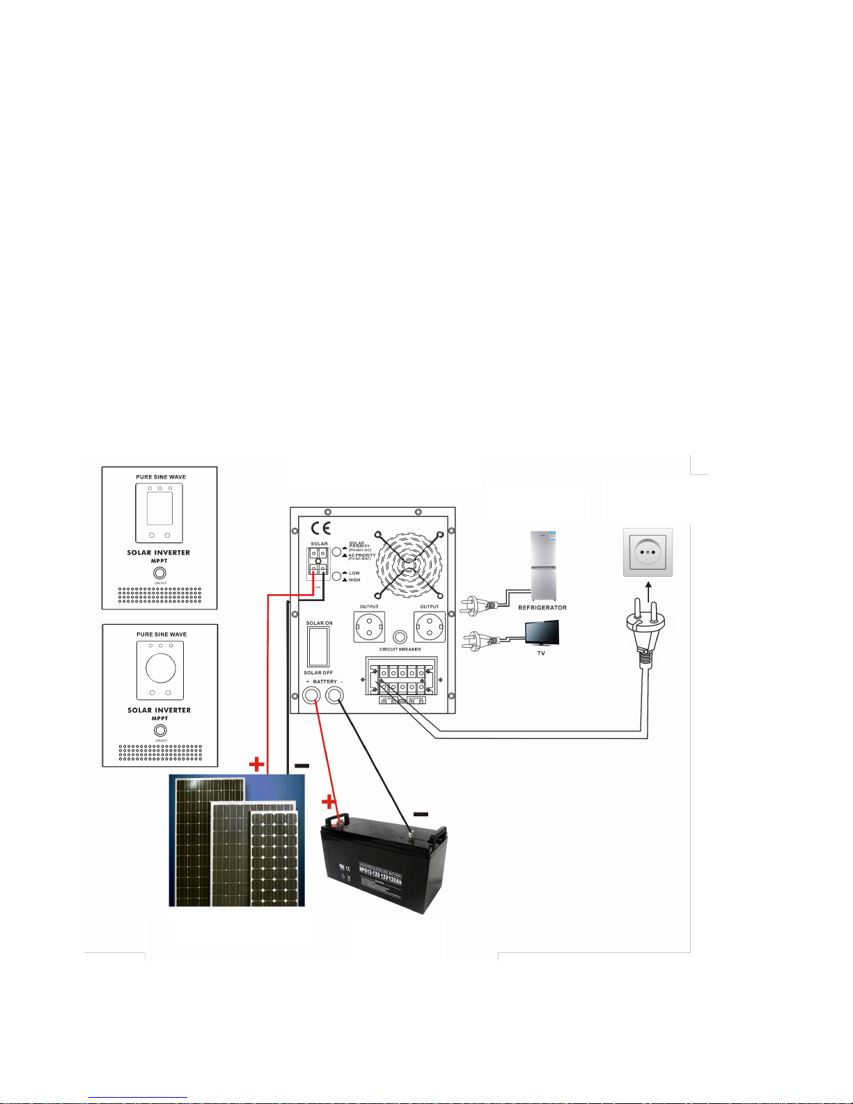
2. Product installation & precautions
2.1 Product installation & connection diagram
Main socket
Loading
Solar inverter
Battery
Solar panel
Page 3
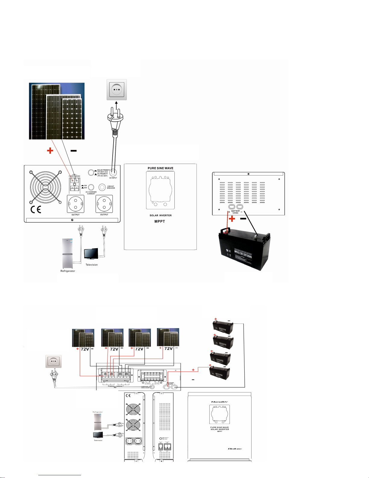
Connection diagram (500VA to 2.5KVA)
Connection diagram (3KVA to 5KVA)
Battery
Loading
Solar inverter
Main socket
Solar panel
Battery
Solar panel
Main socket
Loading
Page 4
Before installation on the wall, please check below size carefully and choose the correct expansion bolt and screw.
Product installation & connection steps:
1) Please open the packing carton to verify that products good, and unplug the power cord to ensure the output terminal
without any connection;
2) Please connect the battery in right way, and check the voltage & polarity of positive/negative carefully;
3) Connect the solar panels properly, and check the voltage & polarity of positive & negative carefully;
4) Select the machine priority mode: for solar energy systems , select the PV priority, otherwise AC priority
5) Press the ON/OFF button to start, to ensure it can work normally and connect the mains.
6) Open the solar input switch for solar charging;
7) Connect the input terminals with the loads which are turn off, and then open them one by one.
2.2 Precautions
1) connect properly to the battery and solar panel, reversed or high voltage will cause serious damage.
2) be connected to ground securely
3) don’t load beyond the rated power. If connect the refrigerators, fans such inductive loads, the loading capacity should
not exceed the 30% of the rated power.
4) don’t install this products outdoors, avoid the electricity leakage caused by any water.
5) when the product work properly, the cabinet will have a certain degree of heat. It should be installed at a distance over
50 cm far away the human venue area. To ensure adequate ventilation around ,and away from flammable materials
6) If the product malfunctions, disconnect the mains input immediately , and then shut down. Disconnect the battery and
solar panel switch, and take note of the failure and fault phenomena, etc, contact your dealer promptly, and give the
products to the professional personnel.
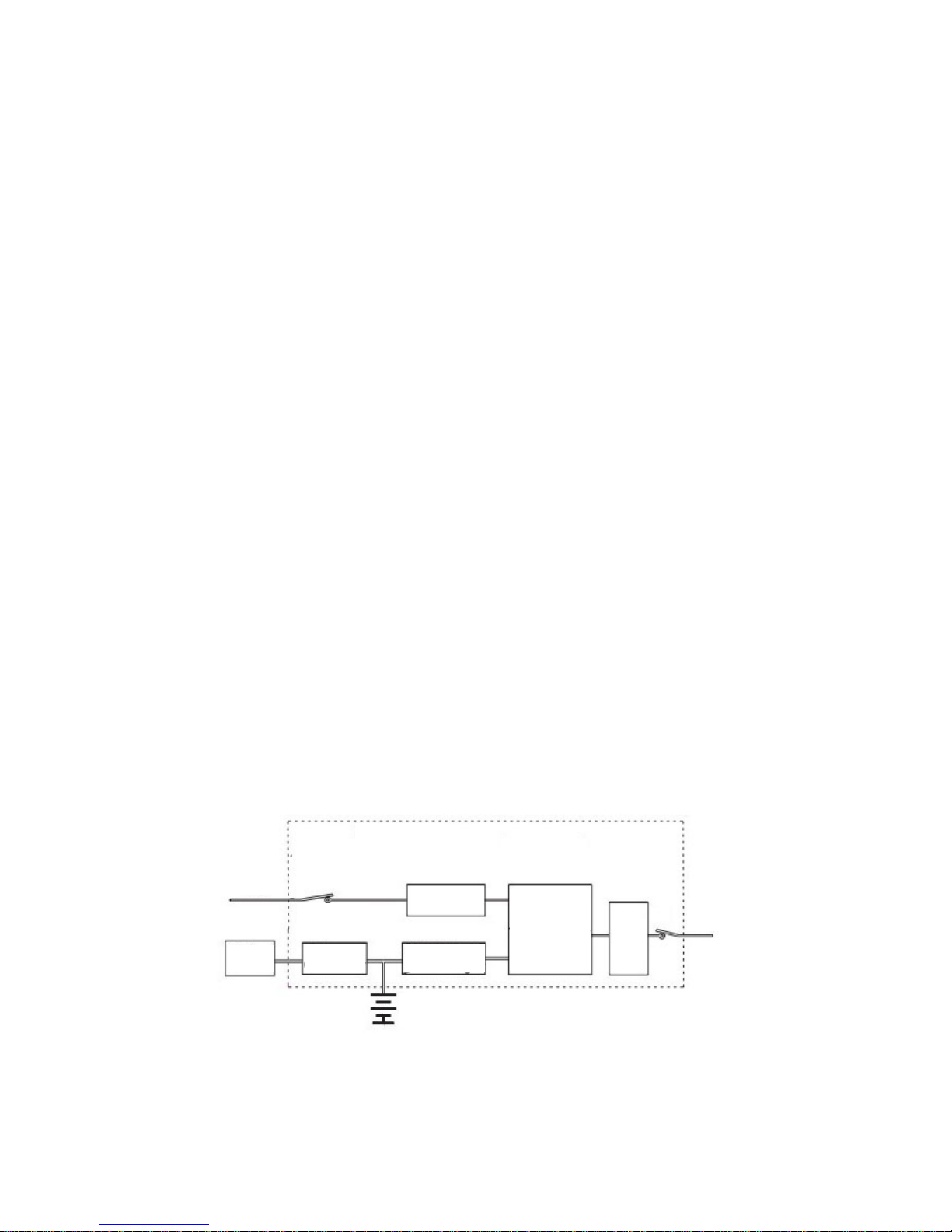
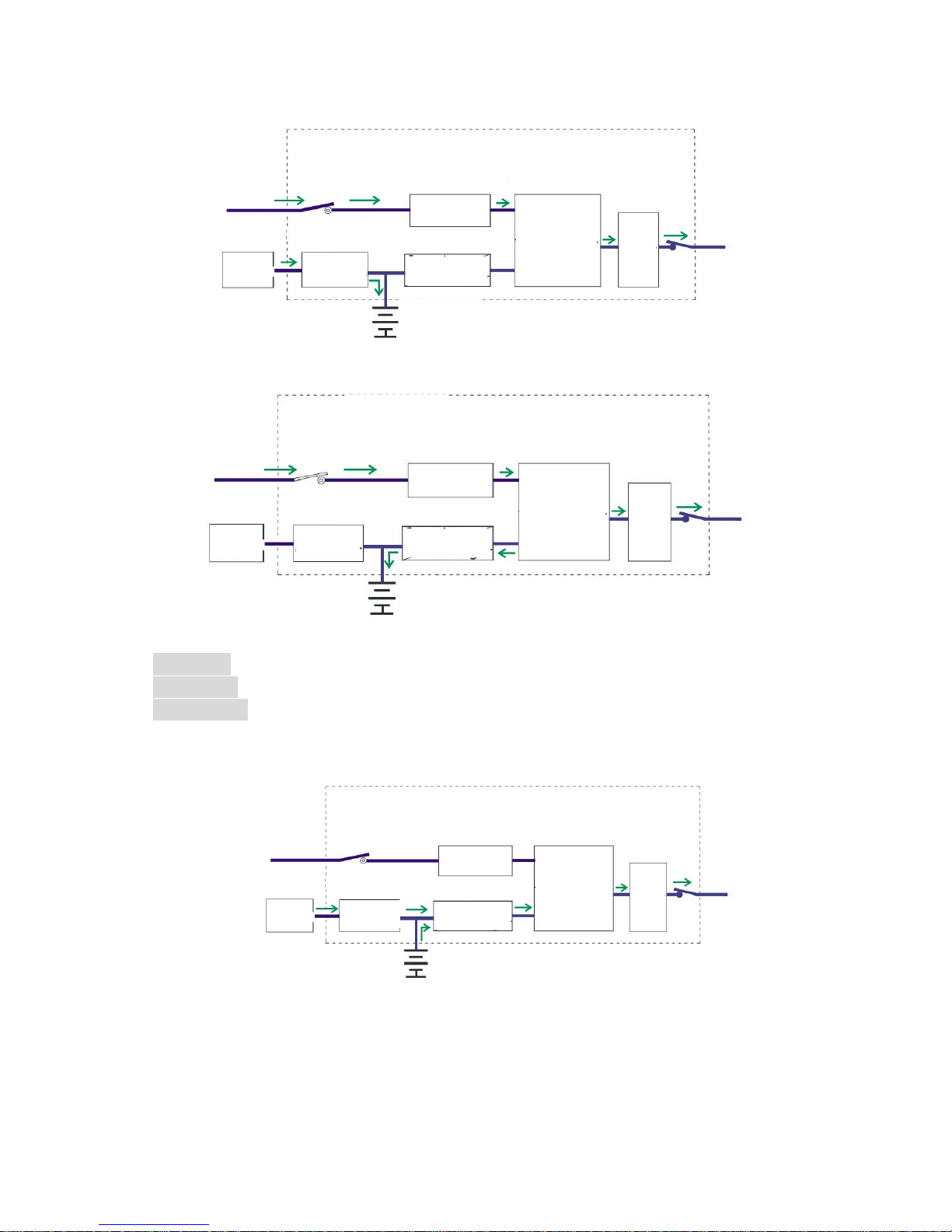
3. Working principle
3.1 System circuit diagram
Inverter
AC
Load
Battery
Solar panel
Solar controller
AVR
Inverter/charger
Isolation
Transformer
Filter
Input
Page 5
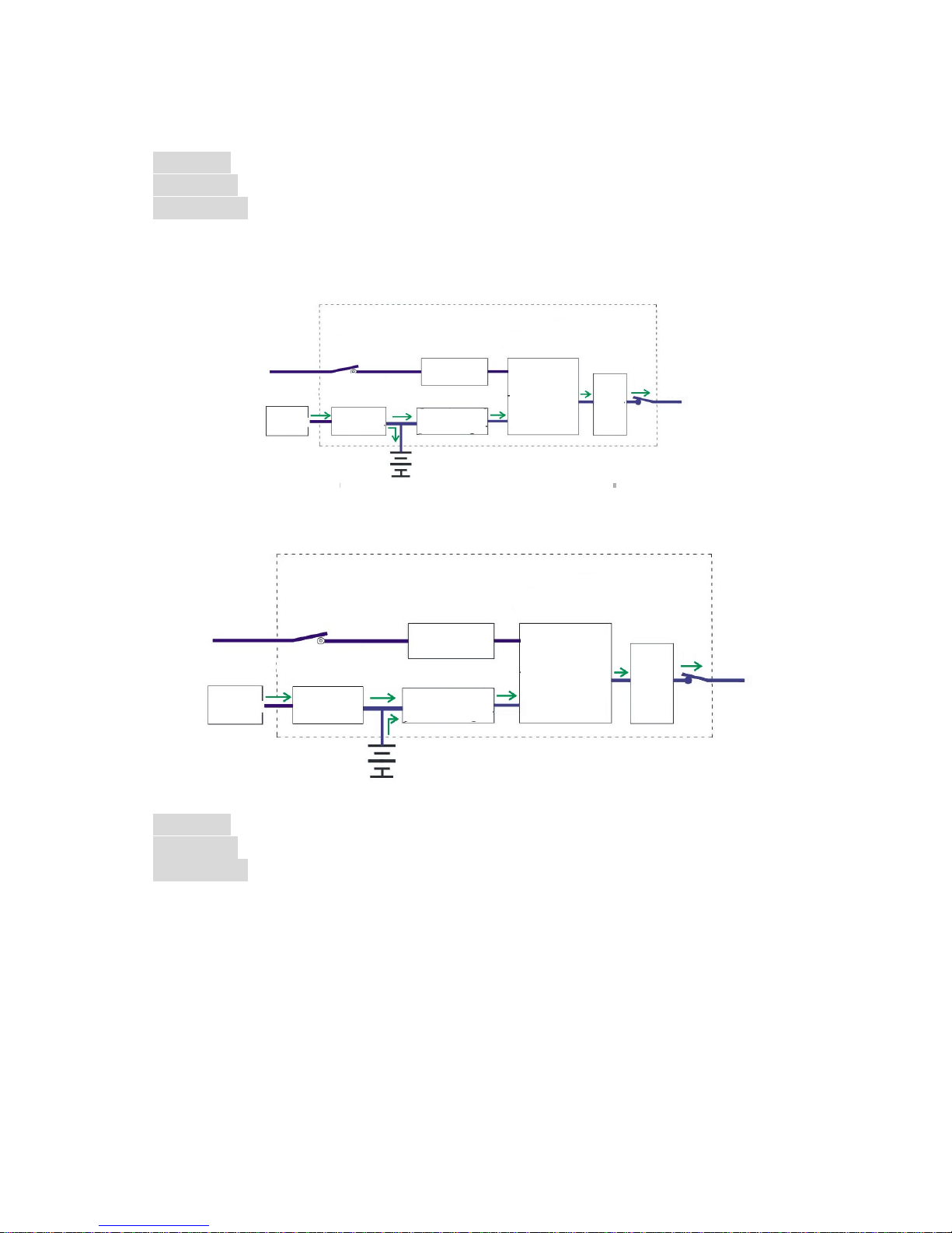
3.2 Working mode:
1) Solar energy: Strong enough
Priority mode: No matter
AC power input: No matter
Solar panel will adjust to the largest state through solar power controller and give power to load through the inverter
(Mains as a standby).If solar energy stronger than output power, it will charge the battery at the same time.
If solar energy less than output power, the system will convert the energy of battery and PV systems and give power
supply to the user equipment.
2) Solar energy: No strong enough
Priority mode: AC priority
AC power input: Normal
AC input will provide power to equipments through regulator by relays and transformer. At this time, PV gives power to
batteries only through MPPT control system.
Load
Filter
Isolation
Transformer
AVR
Inverter
AC
Input
Solar controller
Solar panel
Inverter
Input
AC
Solar panel
Solar controller
AVR
Isolation
Transformer
Filter
Load
Battery
Inverter/charger
Battery
Page 6
During the evening (or rainy days, with no sun), AC power will charge battery by charger inside the inverter.
3) Solar energy: No strong enough
Priority mode: AC priority
AC power input: Wrong
The system will convert the energy of battery and PV systems and give power supply to the user equipment.
During the evening (or rainy days, with no sun), the system will convert the energy of battery and give power supply to
the user equipment.
Inverter
AC
Input
AVR
Isolation
Transformer
Filter
Load
Inverter/charger
Solar controller
Solar panel
Battery
Load
Filter
Isolation
Transformer
Inverter/charger
Battery
Solar controller
Input
AC
AVR
Inverter
Solar panel
Battery
Inverter/charger
AVR
Inverter
AC
Input
Solar controller
Solar panel
Isolation
Transformer
Filter
Load
Page 7
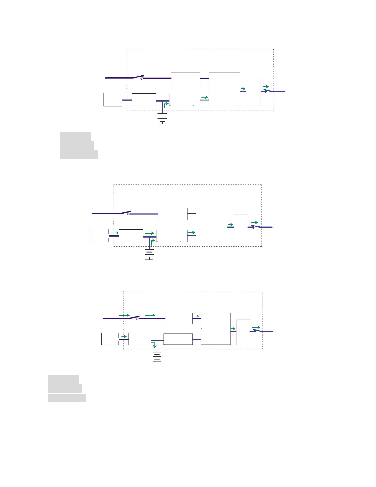
4) Solar energy: No strong enough
Priority mode: PV priority
AC power input: Normal
The system will convert the energy of battery and PV systems and give power supply to the user equipment.
If battery capacity less than 40%, AC input will provide power to equipments through regulator by relays and transformer. At this
time, PV gives power to batteries only through MPPT control system.
5) Solar energy: No strong enough
Priority mode: PV priority
AC power input: Wrong
The system will convert the energy of battery and PV systems and give power supply to the user equipment.
Inverter
Inverter
Inverter
Battery
Battery
AVR
AVR
AC
AC
AC
Input
Input
Input
Solar controller
Solar controller
Battery
Solar controller
Inverter/charger
Inverter/charger
Inverter/charger
Load
Load
Load
Filter
Filter
Filter
Solar panel
Solar panel
Solar panel
Isolation
Transformer
Isolation
Transformer
Isolation
Transformer
AVR
Page 8

If battery capacity less than 30%, the inverter turn off and no power supply to de user equipment. At this time, solar
energy can charge the battery normally.
4. Product panel and display details:
Isolation
Transformer
Isolation
Transformer
Load
Load
AVR AVR
Inverter/charger
Inverter/charger
Input
Input
AC AC
Battery
Battery
Solar controller
Solar controller
Solar panel
Solar panel
Filter
Filter
Inverter
Inverter
Page 9
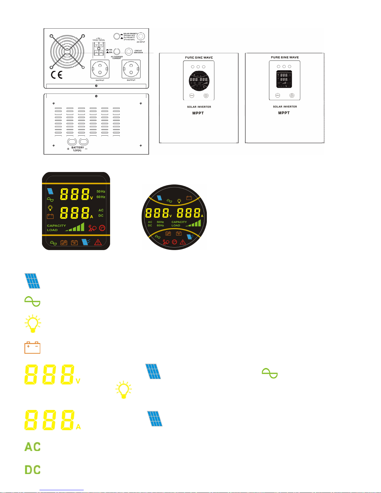
Detail display status by press MENU
- PV
- City power
- Output
- Battery
Voltage indication. When lighting, here shows solar panel voltage; lighting
Here shows city power input voltage; lighting, here shows output voltage.
Current indication. When lighting, here shows solar panel current;
AC voltage indication
DC voltage indication
Page 10

Frequency indication
Loading bar shows the loading situation; Battery bar shows the battery capacity, when in city power charge,
the bar will flashing.
PV charging indication
Battery mode
City power mode
Abnormal/Faulty indication
Overloading indication
Overheating indication
Left : Green LED: Solar panel connect state. Long light means normal. Light off or flash means connect unusual
Middle Yellow LED: Battery connect state : long light means normal, light off or flash means connect unusual
Right Red Led : means abnormal state, light means solar part abnormal
5. ON/OFF Instructions
5.1 About ON/OFF inverter;
1) On: When Mains is normal, inverter will start; when the Mains is abnormal or no input , press the button “ON” in 3 seconds,
it will start also.
2) Off: Press the shut-down (“OFF”) in 3 seconds, it will cut off the output.
SOLAR BATTERY FAULT
Page 11
5.2 About ON/OFF solar controller;
1) On: When PV voltage is in the set range of device & Switcher for solar is “ON”, solar controller will startup automatically
and charge the battery.
2) Off: When PV voltage is lower than the set range of device Or Switcher for solar is “OFF”, solar controller will switch off
automatically.
5.3 Turning on steps;
1) Please ensure the battery connecting properly ( positive/ negative and voltage parameters consistent with the product
identification), and then turn on the battery switch
2) Please ensure the solar panel connecting properly ( positive/ negative and voltage parameters consistent with the
product identification), and then turn on the solar input switch
3) Press the button “on/off” in 3 seconds, and start the inverter
4) Turn on the solar panel input switch , and it will charge automatically
5) Connect the mains properly, after the inverter starts normally, and then start the mains switch
6) After 30 seconds, inverter will output normally and connect the loading, then start the loads one by one.
5.4 Turning off steps:
1) Turn off the loads one by one
2) Press the shut-down ( “Off ”) manually in 3 seconds, and cut the output
3) Unplug the power cable or connector cable, cut off the Mains input ( if no need Mains charging)
4) Turn off the switch of solar panel on the real panel ( If no need Solar panel charging )
5) Turn off the switch of battery on the real panel ( if no need charging)
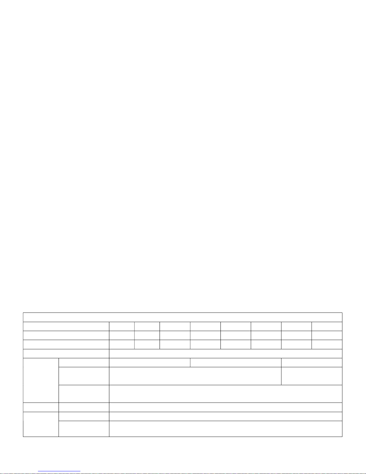
6. Specifications
Solar Integrated Off-Grid Inverter
Model 500VA 800VA 1000VA 1500VA 2000VA 2500VA 3000VA 5000VA
Power Capacity 300W 500W 700W 1050W 1400W 1800W 2100W 3500W
Battery voltage 12Vdc 12Vdc 12Vdc 24Vdc 24Vdc 24Vdc 48Vdc 48Vdc
Working mode PV(Photovoltaic priority) / AC(AC priority)Optional
PV
Input voltage range 15Vdc-50Vdc 30Vdc-50Vdc 60Vdc-100Vdc
Max. charge current
10A/20A/30A//40A Optional
According to print on machine
60A
Max. Conversion
efficiency
98%
Display Panel indicator light LED Graphic Screen LED lights
Mains status
Input voltage range 140Vac~275Vac
Input Frequency range 45-65 Hz (Automatically transfer to inverter power when over frequency)
Page 12

Output voltage range 195Vac~240Vac
Input PF.(AC/DC) 98%
Efficiency Mains mode≥ 96%
Charge current 10A/15A/20A
Mains overload warning until decrease load
Short circuit Yes
Inverter output
Inverter output voltage 220V±3%
Output frequency 50 Hz / 60Hz ± 0.3Hz frequency adaptive
Output power factor ≥0.8
Wave form distortion Linear load≤ 3%
PV-AC transfer time 4Ms typical value Max.6 Ms
Efficiency Inverter mode≥ 80%
Inverter overload 110%-130% shutdown at 30s,130%-150% shutdown at 3s
Short circuit Systems automatically shut down
Alarm
Mains abnormal 1time/1S, silence auto after 5S
Low battery 1time/1S and flash battery last grid
Overload 1time/ 1S and display "overload" grid
Others
Output sockets 1xSchuko, 1xfrench
Surge protection Optional
Ambient temperature 0oC ~ 40oC
Ambient humidity 10% ~ 90%(Non Condensed)
Noise ≤ 50dB
Producer: ntec
Ul. Chorzowska 44B
44-100 Gliwice
Poland
www.qoltec.com
 Loading...