

QOLSYS IQ Hardwire 8 Quick Manual
1. Mount the IQ Hardwire 8 vertically in your desired location.
2. Install provided antenna into the “ANT” terminal at the top of the unit free from
obstructions
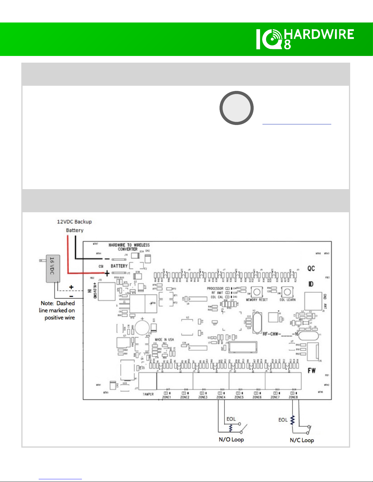
3. Wire all hardwired sensors/leads into the terminals marked “Zone 1-8”
a. All sensors must have a resistor installed between 1k-10k Ohm in either the N/O or N/C position
4. Plug in a 5Ah Max backup battery with included battery leads (battery not included).
5. With provided transformer, connect power supply leads into the terminals marked +16.0V
GND then plug in the IQ Hardwire 8’s power supply. (IMPORTANT: dashed wire is positive)
INFORMATION
The IQ Hardwire 8 offers a cost effective way of integrating hardwired security zones
with the IQ Panel. It includes backup battery charging and features end-of-line resistor
learning, making rewiring different resistor values a thing of the past.
Note: Not for use with life safety devices, such as Smoke or CO detectors
TECHNICAL SPECIFICATIONS
Input Voltage: 16.0VDC Plug-In Transformer
Backup Battery: 12VDC 5AH Max (optional)
Dimensions: 5.5” X 3.5”
Operating Temperature: 32 to 122F (0 to 50C)
Humidity: 95% RH Max
EOL Supervision: 1K to 10K Ohm
Input Zones: 8 (must have resistor)
Zone Type: N/O or N/C compatible
Document #: IQHW8QG
Revision Date: 8/10/17
Qolsys Part #: QS7120-840
STEP 1: INSTALL THE HARDWARE
IN THE BOX
IQ Hardwire 8
Cover
Antenna
Power Supply
4 Screws
8 Resistors (3K)
Battery cables
If mounting inside a metal can, the
antenna must extend outside the
enclosure to ensure RF communication
QUICK GUIDE
Confidential & Proprietary.
Made in Taiwan.
Full installation manual and other
documentation available at
Qolsys.com.
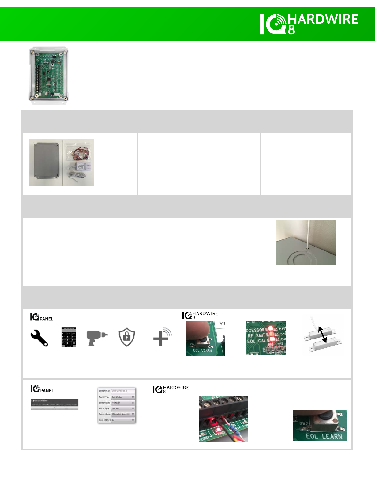
STEP 2: PAIRING INDIVIDUAL ZONES/SENSORS
Settings
Enter installer
code
(Default is 1111)
Installation
Security
Sensors
Auto Learn
Sensor
Press and hold “EOL Learn”
for 1-2 secs. (
all Zone LED’s
flash and then turn off)
EOL Cal LED will turn ON.
This puts the module into
“Enroll Mode”.
Trip (Open/Close)
each hardwired zone
one at a time
The IQ Panel will “chime”
indicating it has found a
new sensor. Touch
“Okay” to proceed.
Customize sensor type
and settings as desired.
Repeat for each zone.
When a sensor has
been tripped, the
resistor value is
calibrated and the
Zone LED will
illuminate and stay
on until you exit
enroll mode.
Once all desired zones have been learned,
press the “EOL Learn” button to exit
“Enroll Mode”. The EOL Cal LED will turn
OFF indicating
you are no
longer in “Enroll
Mode” and all
zone LED’s will
turn OFF.
Page of Qolsys Confidential and Proprietary.1 2
Page of Qolsys Confidential and Proprietary.2 2
TROUBLESHOOTING
EOL LEARN Button: To enter and exit “Enroll Mode” and calibrate resistor values
MEMORY RESET Button: Clears memory and resets the device to factory defaults
PROCESSOR LED: Flashes during normal operation
RF XMIT LED: Flashes when RF transmission is being sent
EOL CAL LED: Flashes when EOL resistors are not calibrated or when no zones have been learned in. ON when device is in “Enroll Mode”. OFF when
device is in “Normal Operation Mode”
ZONE LED: Flashes several times when EOL Cal button is pressed. OFF while in “Enroll Mode” unless a zone has been learned in or tripped, then ON.
OFF while in “Normal Operation Mode” unless a zone is open, then ON.
How to Clear the Memory: Power down the unit by unplugging the battery leads and the power supply. Hold down “Memory Reset” for 3 seconds
while re-applying power to the device. Processor, RF Xmit and EOL Cal LED’s will begin to flash indicating that the module has been reset.
NEED MORE HELP?
CONTACT TECH SUPPORT
(855) 4-QOLSYS
TechSupport@Qolsys.com
?
QUICK GUIDE
WIRING DIAGRAM
 Loading...