

QOLSYS IQ GLASS-S Installation Manual
Sensor: 2.75”H x 3.88”W x 1.5”D
Compatible control panels: Qolsys IQ Panel 2
Frequency: 319.5MHz
Battery: 3V GP CR123A (x2)
Operating Temperature: 14°F to 122°F
Detection Range: 20ft Max and 5ft Min
Intended for use with IQ Panel 2
Supervisory signal interval: 70 min (approximately)!
Intended for use with 3/16” and 1/4” plate or tempered
glass.
SPECIFICATIONS
IQ GLASS S-LINE INSTALLATION MANUAL
Ceiling
Walls
✓
✓
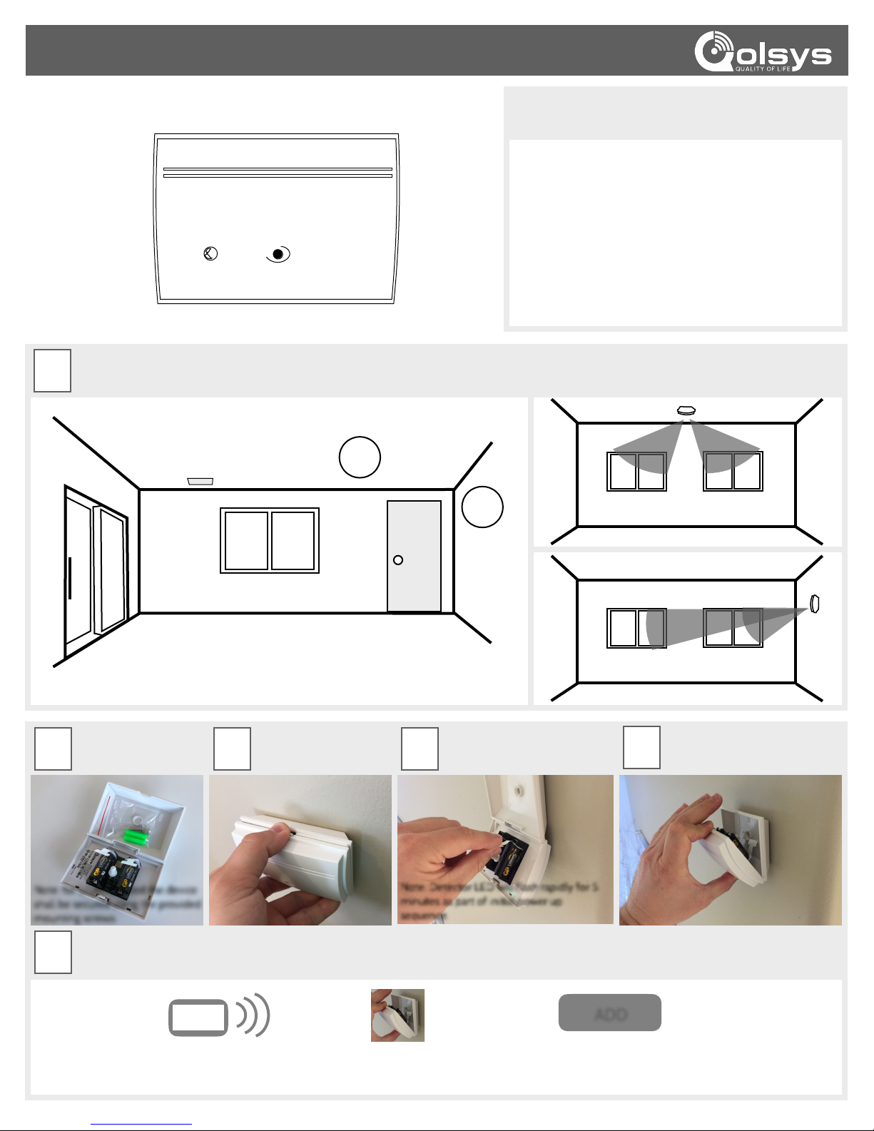
Mounting Height:
The sensor should be mounted between 6.5ft and 8.5ft above the floor.
All protected glass must be within a clear line of sight of the sensor and
within the 20ft max range.
Ceiling mount
Wall mount
CHOOSE
INSTALLATION
LOCATION
STEP
1
IQ GLASS-S
Note: for UL/cUL listed the device
shall be secured using the provided
mounting screws.
STEP 2STEP
3
DETACH
FACE
PLATE
STEP
4
STEP
5
REPLACE
FACE
PLATE
SECURE
TO
SURFACE
REMOVE
BATTERY
TAB
Place your panel in
“autolearn" mode
Open and close the case
to “tamper” the device
Customize name and settings as
desired and touch “ADD”
ADD
STEP
6
LEARN
INTO
PANEL
Note: Detector LED will flash rapidly for 5
minutes as part of initial power up
sequence.
Note: For UL/CUL installations use this device only in conjunction
with compatible Qolsys wireless alarm system IQ Panel 2.
Document#: IQGS-IM-02-18
Revision#: 2/14/18
Issue Date: FEB 2018
Qolsys Product #: QS1431-840
TechSupport@Qolsys.com
CONTACT TECH SUPPORT
GOT QUESTIONS?
Qolsys Inc. proprietary.
Reproduction without permission is not permitted.
FCC ID: 2ABBZ-RF-ARGB
IC: 11817A-RFARGB
This device complies with part 15 of the FCC Rules. Operation is subject to the following two conditions: (1) This device may not cause harmful interference, and (2) this device must accept any interference received, including interference that may cause undesired
operation. Changes or modifications not expressly approved by the party responsible for compliance could void the user's authority to operate the equipment.
This device complies with Industry Canada licence-exempt RSS standard(s). Operation is subject to the following two conditions: (1) this device may not cause interference, and!
(2) this device must accept any interference, including interference that may cause undesired operation of the device.
Cet appareil est conforme avec Industrie Canada exempts de licence standard RSS (s). Son fonctionnement est soumis aux deux conditions suivantes: (1) cet appareil ne doit pas provoquer d'interférences et!
(2) cet appareil doit accepter toute interférence, y compris celles pouvant causer un mauvais fonctionnement de l'appareil.
TESTING
MODE
STEP
7a
FG-701
Glassbreak Simulator
Test Mode:
Place the sensor in test mode by disconnecting the batteries for 30 seconds then
reconnecting. Test mode is active for 5 minutes upon the sensor powering on. The LED blinks
every second when the sensor is in test mode. The IQ Glass-S does not transmit an RF Signal
while it is in Test Mode. Please refer to the table on the right for the LED indicator guide. The
sensor will exit test mode after the first 5 minutes of power up.
CONDITION
RED LED
Initial Power Up
Test Mode
Test Mode, alarm event
Normal Mode, alarm event
Low Battery
Flash rapidly for 5 minutes
Flash once per second
Rapid flash for 2 seconds
SOLID for 5 seconds
Flash once every 30 seconds
LED Indicator Guide:
Sensitivity:
Two dip switches allow you to customize the sensitivity and
detection range of the IQ Glass S. The factory default is set to
MAX. Please refer to the table below to customize the sensitivity.
ON
1
2
SENSITIVITY
DETECTION RANGE
MAX
MEDIUM
LOW
LOWEST
20ft
1
2
13ft
8ft
5ft
OFF
ON
OFF
OFF
OFFONON
ON
Switches:
Set dip switches based on desired detection range.
ACTIVATE
TEST
FLEX
MAN
Red Start"
Button
Set the FG-701 switches to the TEST and MANual
modes.
Position the FG-701 near the protected glass and point
the speaker directly at the glass break detector.
IMPORTANT: If window coverings are present, close
them fully and hold the FG-701 behind the window
coverings for testing.
Press the red start button and the FG-701 will generate
a burst of glass break audio.
If the LED on the IQ Glass-S sensor flashes rapidly for
2 seconds an alarm event has been detected and the
range is acceptable for audio. If the LED does not flash,
position the IQ Glass-S closer to the glass and try
again.
Note: The IQ Glass-S does not transmit an RF Signal
while it is in Test Mode.
1.
2.
3.
To properly test the IQ Glass-S sensor, the
FG-701 Glassbreak Simulator is required.
STEP
7b
STEP
7c
TESTING
MODE
TESTING
MODE
SECURE
CONNECTS
USING
319.5 MHz
Equipment!
BP21056
 Loading...