


5-Port Gigabit Management PoE switch
User Manual

Default-IP
192.168.2.1
Username & Password:
admin

Table of Contents
Chapter 1 Introduction to the Web Smart PoE Switch ······································ 4
1.3 LEDs Definition ······················································································ 4
1.4 The Rear Panel ······················································································ 4
1.5 Installation ····························································································· 5
Chapter 2 Basic Web Management Information ············································· 7
2.1 System login ·························································································· 7
2.2 The Graphic User Interface ······································································· 7
Chapter 3 Web Management Configuration ··················································· 9
3.1 System ································································································· 9
3.2 Management ························································································ 10
3.2.1 Firmware Upgrade ·············································································· 10
3.3 Port Status ··························································································· 12
3.4 VLAN ·································································································· 13
3.4.1 IEEE 802.1Q VLAN ············································································· 13
3.4.2 Port-Based VLAN ················································································ 14
3.5 Trunking ······························································································ 15
3.6 Mirror ·································································································· 16
3.7 QoS ···································································································· 17
3.7.1 Port-Based QoS·················································································· 17
3.7.2 IEEE 802.1p QoS ················································································ 18
3.8 Broadcast Storm Control ········································································· 19
3.9 Loop Detect / Prevent ············································································· 20
3.10 IGMP Snooping ··················································································· 21
3.11 PoE ··································································································· 22
3.12 Password ··························································································· 23
3.13 Logout ······························································································· 24
Product Specifications ················································································· 25
Chapter 1 Introduction to the Web Smart PoE Switch
1.3 LEDs Definition
This device provides extensive LEDs to show the activities on power, system and ports.
See the following description for your reference:
LED
Status
Operation
PWR/SYS
Steady Green
Power on.
Blinking Green
System booting up.
Off
Power off or fail.
PoE/Max
Steady Green
Over PoE max power budget (50W)
Off
No over PoE max power budget (50W)
LINK/ACT
Steady Green
1000Mbps connected.
Steady Amber
10/100Mbps connected
Blinking
Sending or receiving data.
Off
Port disconnected or link fail.
PoE
Steady Green
PoE power output on.
Off
PoE power output off.
The Reset Button
Reset the switch to its factory default configuration via the RESET button. Press the RESET button
for ten seconds and release. The switch automatically reboots and reloads its factory configuration
file. The RESET button is on the front panel of the switch.
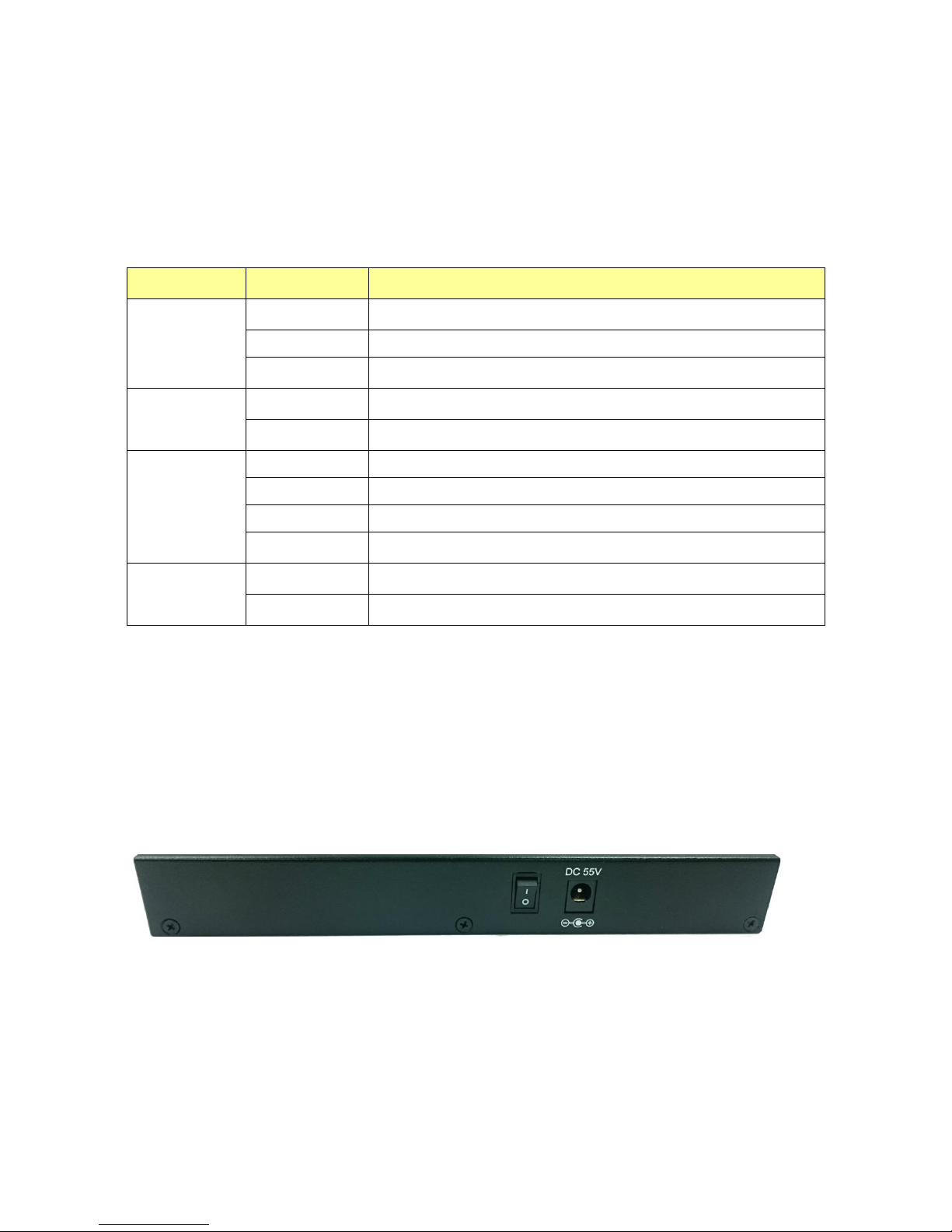
1.4 The Rear Panel
The following figure shows the rear panel of the switch:
Power Receptacle
To be compatible with the electric service standards around the world, the switch is designed to
afford the power supply in the range from 100 to 240 VAC, 50/60 Hz. Please make sure that your
outlet standard to be within this range.
To power on the switch, please plug the female end of the power cord firmly into the receptacle of
the switch, the other end into an electric service outlet, and use the POWER ON/OFF switch to
have the Switch power on or off. After the switch powered on, please check if the PWR/SYS LED is
lit for a normal power status.

1.5 Installation
This switch can be placed on your desktop directly, or mounted on the wall. Please refer to the
instructions for installation.
Before installing the switch, we recommend:
1. The switch is placed with appropriate ventilation environment. A minimum 25 mm space around
the unit is recommended.
2. The switch and the relevant components are away from sources of electrical noise such as
radios, transmitters and broadband amplifiers
3. The switch is away from environments beyond recommend moisture
Desktop Installation
1. Install the switch on a level surface that can support the weight of the unit and the relevant
components.
2. Plug the switch with the power cable of adaptor and plug the power adaptor to the power outlet.
Wall-mount Installation
The switch may be standalone, or mounted on wall. Wall mounting facilitate to an orderly
installation when you are going to install series of networking devices.
Procedures to Wall-mount the switch:
1. Screw the two screws provided with your Switch into the wall. Use screws with 6 mm ~ 8 mm (0.24" ~ 0.31") wide
heads. Do not screw the screws all the way in to the wall; leave a small gap between the head of the screw and the
wall.
2. Align the holes on the back of the Switch with the screws on the wall. Hang the Switch on the screws.
Note:
The Switch should be wall-mounted horizontally. The Switch's side panels with ventilation slots
should not be facing up or down as this position is less safe.
Installing Network Cables
1. Crossover or straight-through cable: All the ports on the switch support Auto-MDI/MDI-X
functionality. Both straight-through or crossover cables can be used as the media to connect the
switch with PCs as well as other devices like switches, hubs or router.

2. Category 3, 4, 5 or 5e, 6 UTP/STP cable: To make a valid connection and obtain the optimal
performance, an appropriate cable that corresponds to different transmitting/receiving speed is
required. To choose a suitable cable, please refer to the following table.
Media
Speed
Wiring
10/100/1000 Mbps
copper
10 Mbps
Category 3,4,5 UTP/STP
100 Mbps
Category 5 UTP/STP
1000 Mbps
Category 5e, 6 UTP/STP
Chapter 2 Basic Web Management Information
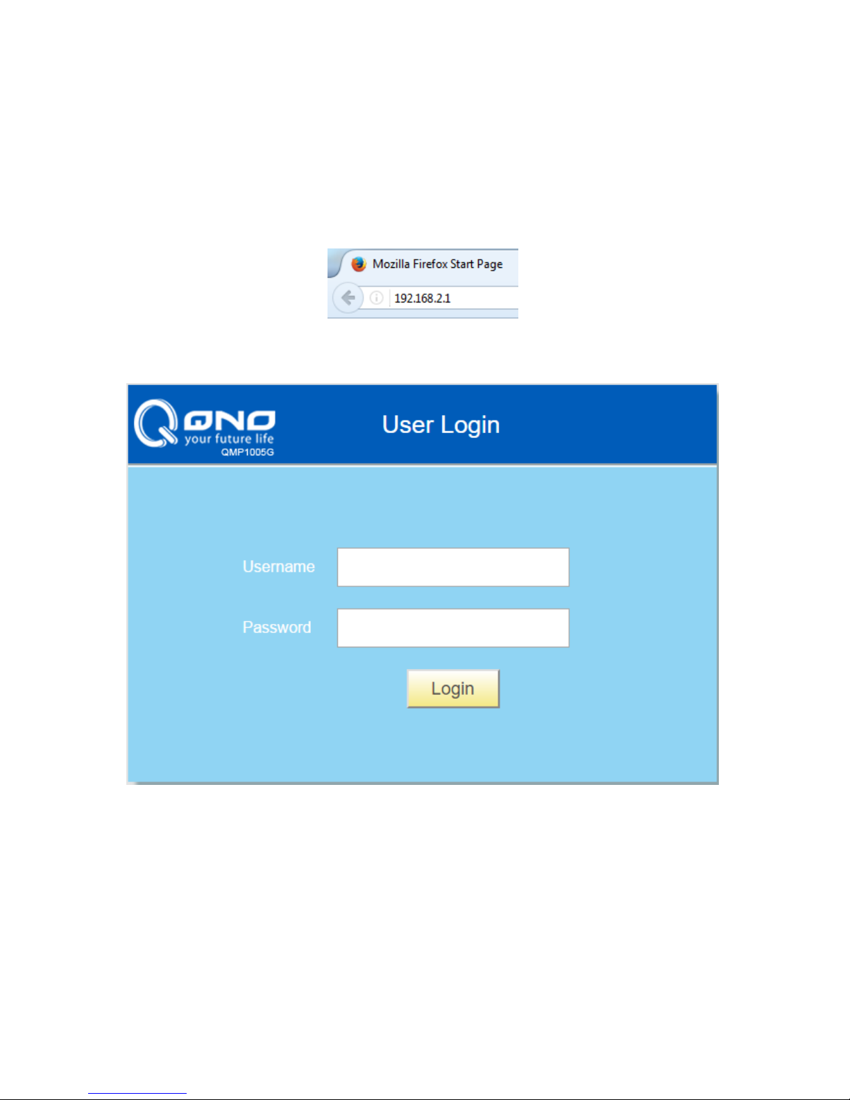
2.1 System login
1. Start your web browser.
2. Type “http://”and the IP address of the switch (for example, the default management IP address
is 192.168.2.1) in the Location or Address field. Press [ENTER].
3. The login screen appears. The default username and password are “admin”, so you can click
Login and go to the web configuration screen directly.
2.2 The Graphic User Interface
After the password authorization, the System page shows up. You may click on each folder on the
left column of each page to get access to each configuration page. The Graphic User Interface is as
follows:
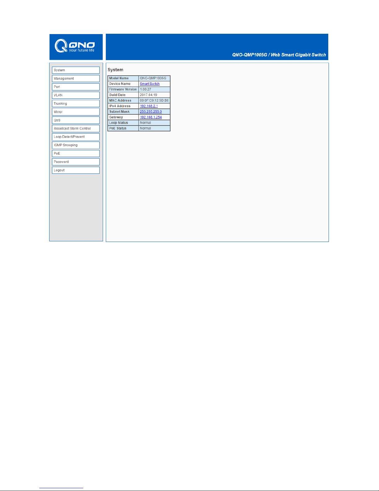
A –Click the menu items to open the screen in the main window.
B –Displays system information such as MAC address and firmware version and so on.

Chapter 3 Web Management Configuration
3.1 System
System page allow user to configure and browse some system information such as Model Name,
Device Name, Firmware Version, MAC address, IP address, Loop status and PoE status.
User could configure Device Name and IP address in System page.
LABEL
DESCRIPTION
Device Name
Device name of the switch.
IPv4 Address /
Subnet Mask
The IP address of the switch.

3.2 Management
In Management page, “Reset” / “Reboot” button can restore default and reboot system. System
also can backup and restore configuration file via “Restore” / “Backup” button. Firmware can be
upgraded via “Upgrade” button.
3.2.1 Firmware Upgrade
User has to enter Loader Mode to upgrade firmware. Click “Upgrade”, it will pop up this warning
message, and then click “OK” to enter Loader Mode.
In Loader Mode, click “Browse…” and navigate to the location of the firmware upgrade file.
Select the firmware upgrade file. Its name will appear in the Upgrade File field. And then click the
“Upgrade” button to commence the firmware upgrade.

Click OK to upgrade firmware.
Wait for 30 seconds. When the upgrading process is done, it will redirect to Login page.

3.3 Port Status
In Port page, you can see the Link Status and TX/RX counts of all ports. You also can click “Clear
Counters” to reset the TX/RX counts.

3.4 VLAN
A virtual local area network, virtual LAN or VLAN, is a group of hosts with a common set of
requirements that communicate as if they were attached to the same broadcast domain, regardless
of their physical location. A VLAN has the same attributes as a physical local area network (LAN),
but it allows for end stations to be grouped together even if they are not located on the same
network switch. VLAN membership can be configured through software instead of physically
relocating devices or connections.
In “VLAN” page, IEEE 802.1Q VLAN and Port-Based VLAN are supported as follows.
3.4.1 IEEE 802.1Q VLAN
Click Create New VLAN to add a VLAN tag, and it will show as below. Enter the VLAN ID and
select the VLAN member.

3.4.2 Port-Based VLAN
Click Add VLAN, and it will show as below. Select the VLAN member port.

3.5 Trunking
Link Aggregation Control Protocol (LACP) that allows you to bundle several physical ports together
to form a single logical channel. LACP allows a switch to negotiate an automatic bundle by sending
LACP packets to the peer.
Select Enable to enable LACP function and connect Port 1 and Port 2 to another switch that
supports LACP function.

3.6 Mirror
The Mirror function copies all the packets that are transmitted by the source port to the destination
port. It allows administrators to analyze and monitor the traffic of the monitored ports.
LABEL
DESCRIPTION
Enable Mirror
Check to enable Mirror function.
Mirror Direction
Select mirror direction: Ingress, Egress or Both
Monitor Port
Select monitor port : Port1 ~ Port 5
Mirrored Port List
Select mirrored port.
Apply
Click Apply to save your changes to the switch.

3.7 QoS
Quality of Service (QoS) features are used to prioritize the use of bandwidth in a switch. When QoS
features are enabled, traffic is classified as it arrives at the switch, and processed through on the
basis of configured priorities.
3.7.1 Port-Based QoS
LABEL
DESCRIPTION
Scheduler Method
Select WFQ(Weighted Fair Queuing) or Strict Priority
Port
Queue ID to configure for each port
Weight
If the queue type is WFQ, set the queue weight for the queue.
Apply
Click Apply to save your changes to the switch.

3.7.2 IEEE 802.1p QoS
LABEL
DESCRIPTION
Scheduler Method
Select WFQ(Weighted Fair Queuing) or Strict Priority
Priority
Queue ID to configure
Weight
If the queue type is WFQ, set the queue weight for the queue.
Apply
Click Apply to save your changes to the switch.

3.8 Broadcast Storm Control
Broadcast storm control limits the number of broadcast frames that can be stored in the switch
buffer or sent our from the switch. Broadcast frames that arrive when the buffer is full are discarded.
Select the limitation to reduce broadcast traffic coming into you network.
The types of storm control include Broadcast, Multicast and DLF (Destination Lookup Failure).
Limits are as follows: no limit, 512K/s, 1M/s, 2M/s, 4M/s, 8M/s, 16M/s, 32M/s, 64M/s, 128M/s,
256M/s and 512M/s.

3.9 Loop Detect / Prevent
In “Loop Detect/Prevent” page, system will detect/prevent loop automatically based on your
selection.
Loop Detection: the LINK/ACT LED will blink in a regular time (about 1s).
Loop Prevention: One Ethernet port will be disabled and then up again.

3.10 IGMP Snooping
IGMP snooping is the process of listening to Internet Group Management Protocol (IGMP) network
traffic. The feature allows a network switch to listen in on the IGMP conversation between hosts and
switch. By listening to these conversations the switch maintains a map of which links need which IP
multicast streams. Multicasts may be filtered from the links which do not need them and thus
controls which ports receive specific multicast traffic.
Check “Blocking Unknown Multicast” and “Enable IGMP Snooping” to avoid the Multicast flood.

3.11 PoE
In “PoE” page, PoE power budget, port status, etc. are shown below.
Click port number above, you can turn on/off PoE port on PoE port configuration page as below.

3.12 Password
In “Password” page, you can change user name and password for security.

3.13 Logout
Click “Logout” to logout the switch. After logout, Web UI will be redirect to login page immediately.

Product Specifications
Standard
IEEE802.3, IEEE802.3u, and IEEE802.3ab
IEEE 802.3x flow control
IEEE 802.1p class of service, priority protocols
IEEE 802.1Q VLAN tagging
IEEE 802.3ad LACP aggregation
IEEE 802.3az Energy Efficient Ethernet(EEE)
IEEE 802.3af PoE
IEEE 802.3at PoE+
Interface
5* 10/100/1000Mbps ports
4* PoE ports (support IEEE 802.3af and IEEE802.3at)
Transmission
Mode
10/100Mbps: Full-duplex, Half-duplex
1000Mbps: Full-duplex
MAC Address
Table
2000
Jumbo Frame
9KB
Buffer Memory
128KB
Temperature
Operating: 0 ~ 50℃
Storage : -40 ~ 70℃
Humidity
Operating: 10% ~ 90% RH (non-condensing)
Storage : 5% ~ 90% RH (non-condensing)
LED Indications
1*PWR/SYS LED(Green)
1*PoE Max LED(Green)
5*Gigabit port LEDs(Link/Act: Green/Amber)
4*PoE port LEDs(Green)
Power Supply
AC-to-DC external power adapter
Input: 100-240V AC
Output: 55V DC/1.3A
Dimensions
193 x 84 x 26 mm
Case Material
Metal, Fan-less
 Loading...