

Page 1

English User’s Manual
4 WAN
Enterprise Multi-WAN
VPN QoS Router
Load Balancing, Bandwidth M
anagement,
VPN & Network Security Management
Page 2

Enterprise Multi-WAN VPN QoS Router
I
Product Manual Using Permit Agreement
[Product Manual (hereafter the "Manual") Using Permit Agreement] hereafter the "Agreement" is
the using permit of the Manual, and the relevant rights and obligations between the users and
Qno Technology Inc (hereafter "Qno"), and is the exclusion to remit or limit the liability of Qno.
The users who obtain the file of this manual directly or indirectly, and users who use the relevant
services, must obey this Agreement.
Important Notice: Qno would like to remind the users to read the clauses of the "Agreement"
before downloading and reading this Manual. Unless you accept the clauses of this "Agreement",
please return this Manual and relevant services. The downloading or reading of this Manual is
regarded as accepting this "Agreement" and the restriction of clauses in this "Agreement".
【1】 Statement of Intellectual Property
Any text and corresponding combination, diagram, interface design, printing materials or
electronic file are protected by copyright of our country, clauses of international copyright and
other regulations of intellectual property. When the user copies the "Manual", this statement of
intellectual property must also be copied and indicated. Otherwise, Qno regards it as tort and
relevant duty will be prosecuted as well.
【2】Scope of Authority of "Manual"
The user may install, use, display and read this "Manual on the complete set of computer.
【3】User Notice
If users obey the law and this Agreement, they may use this "Manual" in accordance with
"Agreement". If the users violate the "Agreement", Qno will terminate the using authority and
destroy the copy of this "Manual". The "hardcopy or softcopy" of this Manual is restricted using for
information, non-commercial and personal purpose. Besides, it is not allowed to copy or
announce on any network computer. Furthermore, it is not allowed to disseminate on any media.
It is not allowed to modify any part of the "file". Using for other purposes is prohibited by law and
Page 3

Enterprise Multi-WAN VPN QoS Router
II
it may cause serious civil and criminal punishment. The transgressor will receive the accusation
possibly.
【4】Legal Liability and Exclusion
【4-1】Qno will check the mistake of the texts and diagrams with all strength. However, Qno,
distributors, and resellers do not bear any liability for direct or indirect economic loss, data loss or
other corresponding commercial loss to the user or relevant personnel due to the possible
omission.
【4-2】In order to protect the autonomy of the business development and adjustment of Qno, Qno
reserves the right to adjust or terminate the software / Manual any time without informing the
users. There will be no further notice regarding the product upgrade or change of technical
specification. If it is necessary, the change or termination will be announced in the relevant block
of the Qno website.
【4-3】All the set parameters are examples and they are for reference only. You may also purpose
your opinion or suggestion. We will take it as reference and they may be amended in the next
version.
【4-4】This Manual explains the configuration of all functions for the products of the same series.
The actual functions of the product may vary with the model. Therefore, some functions may not
be found on the product you purchased.
【4-5】Qno reserves the right to change the file content of this Manual and the Manual content
may not be updated instantly. To know more about the updated information of the product, please
visit Qno official website.
【4-6】Qno (and / or) distributors hereby declares that no liability will be born for any guarantee
and condition of the corresponding information. The guarantee and condition include tacit
guarantee and condition about marketability, suitability for special purposes, ownership, and
non-infringement. The name of the companies and products mentioned may be the trademark of
the owners. Qno (and/or) the distributors do not provide the product or software of any third
party company. Under any circumstance, Qno and / or distributors bear no liability for special,
indirect, derivative loss or any type of loss in the lawsuit caused by usage or information on the
file, no matter the lawsuit is related to agreement, omission, or other tort.
【5】Other Clauses
【5-1】The potency of this Agreement is over any other verbal or written record. The invalidation
of part or whole of any clause does not affect the potency of other clauses.
【5-2】The power of interpretation, potency and dispute are applicable for the law of Taiwan. If
Page 4

Enterprise Multi-WAN VPN QoS Router
III
there is any dissension or dispute between the users and Qno, it should be attempted to solve by
consultation first. If it is not solved by consultation, user agrees that the dissension or dispute is
brought to trial in the jurisdiction of the court in the location of Qno. In Mainland China, the "China
International Economic and Trade Arbitration Commission" is the arbitration organization.
Page 5

Enterprise Multi-WAN VPN QoS Router
IV
Content
I. Introduction.................................................................................................................................................1
II. Multi- WAN VPN Router Installation .....................................................................................................3
2.1 Systematic Setting Process .................................................................................................................... 3
2.2 Setting Flow Chart ..................................................................................................................................... 3
III. Hardware Installation.............................................................................................................................6
3.1 LED Signal..................................................................................................................................................... 6
3.2 VPN Router Network Connection .......................................................................................................... 8
IV. Login..........................................................................................................................................................9
V. Device Spec Verification, Status Display and Login Password and Time Setting ..............................11
5.1 Home Page.................................................................................................................................................. 11
5.1.1 WAN Status.......................................................................................................................................11
5.1.2 Physical Port Status.......................................................................................................................12
5.1.3 System Information.......................................................................................................................13
5.1.4 Firewall Status .................................................................................................................................14
5.1.5 VPN Status ........................................................................................................................................ 15
5.1.6 Log Setting Status .........................................................................................................................15
5.2 Change and Set Login Password and Time .................................................................................... 16
5.2.1 Password Setting ............................................................................................................................16
5.2.2 Time.....................................................................................................................................................17
VI. Network...................................................................................................................................................19
6.1 Network Connection ................................................................................................................................ 19
6.1.1 Host Name and Domain Name..................................................................................................20
6.1.2 LAN Setting....................................................................................................................................... 20
6.1.3 WAN & DMZ Settings .................................................................................................................... 21
6.2 Multi- WAN Setting .................................................................................................................................. 35
6.2.1 Load Balance Mode ........................................................................................................................35
6.2.2 Network Detection Service ......................................................................................................... 39
6.2.3 Protocol Binding ..............................................................................................................................42
VII. Port Management.................................................................................................................................52
7.1 Setup............................................................................................................................................................. 52
7.2 Port Status .................................................................................................................................................. 55
7.3 IP/ DHCP...................................................................................................................................................... 57
7.4 DHCP Status............................................................................................................................................... 59
7.5 IP & MAC Binding ..................................................................................................................................... 61
Page 6

Enterprise Multi-WAN VPN QoS Router
V
7.6 IP Grouping................................................................................................................................................. 65
VIII. QoS (Quality of Service).....................................................................................................................66
8.1 Bandwidth Management ........................................................................................................................ 67
8.1.1 The Maximum Bandwidth provided by ISP...........................................................................67
8.1.2 QoS ......................................................................................................................................................68
8.2 Session control.......................................................................................................................................... 74
8.3 Smart QoS .................................................................................................................................................. 77
IX. Firewall ...................................................................................................................................................79
9.1 General Policy ............................................................................................................................................ 79
9.2 Restrict Application.................................................................................................................................. 83
9.3 Access Rule................................................................................................................................................. 85
9.4 Content Filter ............................................................................................................................................. 89
X. VPN (Virtual Private Network)..............................................................................................................93
10.1. VPN ............................................................................................................................................................ 93
10.1.1. Display All VPN Summary .......................................................................................................93
10.1.2. Add a New VPN Tunnel............................................................................................................. 98
10.1.3. PPTP Setting ...............................................................................................................................128
10.1.4. VPN Pass Through ....................................................................................................................131
10.2. QnoKey................................................................................................................................................... 132
10.2.1. QnoKey Summary ....................................................................................................................132
10.2.2 Qnokey Group Setup ................................................................................................................133
10.2.3 Qnokey Account List .................................................................................................................136
10.3. QVM VPN Function Setup ................................................................................................................ 138
10.3.1. QVM Server Settings ...............................................................................................................139
10.3.2. QVM Status .................................................................................................................................140
10.3.3. QVM Client Settings................................................................................................................. 142
XI. Virtue Route..........................................................................................................................................144
11.1 Virtue Route Server (PPTP Server) ............................................................................................... 146
11.2 Virtue Route Client .............................................................................................................................. 149
XII. Advanced Function.............................................................................................................................152
12.1 DMZ Host/ Port Range Forwarding................................................................................................ 152
12.1.1 DMZ Host ......................................................................................................................................152
12.1.2 Port Range Forwarding.............................................................................................................153
12.1.3 Port Triggering.............................................................................................................................155
12.2 UPnP ......................................................................................................................................................... 157
Page 7

Enterprise Multi-WAN VPN QoS Router
VI
12.3 Routing .................................................................................................................................................... 159
12.3.1 Dynamic Routing........................................................................................................................159
12.3.2 Static Routing..............................................................................................................................160
12.4 One to One NAT.................................................................................................................................... 162
12.5 DDNS- Dynamic Domain Name Service...................................................................................... 164
12.6 MAC Clone .............................................................................................................................................. 169
XIII. System Tool........................................................................................................................................170
13.1 Diagnostic ............................................................................................................................................... 170
13.2 Firmware Upgrade ............................................................................................................................... 172
13.3 Setting Backup...................................................................................................................................... 173
13.4 SNMP ........................................................................................................................................................ 174
13.5 System Recover.................................................................................................................................... 176
XIV. Log.......................................................................................................................................................178
14.1 System Log ............................................................................................................................................ 178
14.2 System Statistic ................................................................................................................................... 185
14.3 Traffic Statistic ...................................................................................................................................... 187
14.4 IP/ Port Statistic ................................................................................................................................... 189
XV. Log out..................................................................................................................................................192
Appendix I: User Interface and User Manual Chapter Cross Reference..............................................193
Appendix II::::Troubleshooting..................................................................................................................196
(1) Block BT Download................................................................................................................................. 196
(2)Shock Wave and Worm Virus Prevention ................................................................................... 197
(3)Block QQLive Video Broadcast Setting ........................................................................................ 199
(4)ARP Virus Attack Prevention............................................................................................................ 201
Appendix III::::Qno Technical Support Information ..............................................................................210
Page 8

Enterprise Multi-WAN VPN QoS Router
1
I. Introduction
Enterprise Multi-WAN VPN QoS Router (referred as VPN Router hereby) is a business
level security router that efficiently integrates new generation multiple WAN-port devices. It
meets the needs of both medium and large-scale enterprises, internet cafés, and
communities, etc. Apart from its internet connectivity that suits the broadband market, VPN
Router has a built-in 10/100Mbps QoS and VLAN switching board which enables it to fulfill
most enterprise and internet cafe firewall needs.
VPN Router has 2-4 10/100 Base-T/TX Ethernets (RJ45) WAN ports. These WAN ports
can support auto load balance mode, exclusive mode (remaining WAN balance), and stategy
routing mode for high-efficiency network. They offer super flexibility for network set-up.
Moreover, these WAN ports also support DHCP, fixed IP, PPPoE, transparent bridge, VPN
connection, port binding, static routing, dynamic routing, NAT, one to one NAT, PAT, MAC
Clone, as well as DDNS. As for LAN ports including one DMZ, they support 10/100 Base-T/TX
Ethernet (RJ45) and provide the features of virtual route, Microsoft UPnP, VLAN, Multi Subnet,
and transparent bridge mode. Internet IP addresses can also be used in intranet.
To fulfill the requirement for a highly secure and integrated firewall, VPN Router has a
high-speed, high-efficiency four-core Intel IXP processor embedded. With high processing
speed, plusing high standard SDRAM and Flash, VPN Router brings users super networking
efficiency. Its processing speed and capacity are almost equal to those of expensive
enterprise-level VPN Routers. This is why the device is so popular with modern enterprises.
In addition to internet connectability, for the broadband market, VPN Router has the
function of VPN virtual network connection. It is equipped with a virtual private network
hardware acceleration mode which is widely used in modern enterprises, and offers full VPN
functionality.
Qno is a supporter of the IPSec Protocol. IPSec VPN provides DES, 3DES, AES-128
encryption, MD5, SH1 certification, IKE Pre-Share Key, or manual password interchange. VPN
Router also supports aggressive mode. When a connection is lost, VPN Router will
automatically re-connect. In addition, the device features NetBIOS transparency, and
supports IP grouping for connections between clients and host in the virtual private network.
VPN Router offers the function of a standard PPTP server, which is equipped with
connection setting status. Each WAN port can be set up with multiple DDNS at the same time.
It is also capable of establishing VPN connections with dynamic IP addresses.
VPN Router also has unique QVM VPN- SmartLink IPSec VPN. Just input VPN server IP,
user name, and password, and IPSec VPN will be automatically set up. Through VPN Router
exclusive QVM function, users can set up QVM to work as a server, and have it accept other
QVM series products from client ports. QVM offers easy VPN allocation for users; users can do
it even without a network administrator. VPN Router enables enterprises to benefit from VPN
without being troubled with technical and network management problems. The central
control function enables the host to log in remote client computers at any time. Security and
secrecy are guaranteed to meet the IPSec standard, so as to ensure the continuity of VPN
service.
Page 9

Enterprise Multi-WAN VPN QoS Router
2
The advanced built-in firewall function enables VPN Router to resist most attacks from
the Internet. It utilizes active detection technology SPI (Stateful Packet Inspection). The SPI
firewall functions mainly within the network by dynamically inspecting each link. The SPI
firewall also has a warning function for the application process; therefore, it can refuse links
to non-standard communication protocols. VPN Router supports network address translation
(NAT) function and routing modes. It makes the network environment more flexible and
easier to manage.
Through web- based UI, VPN Router enables enterprises to have their own network
access rules . To control web access, users can build and edit filter lists. It also enables users
to ban or monitor websites according to their needs. By the filter setting and complete OS
management, school and business internet management will be clearly improved. VPN
Router offers various on-line SysLog records. It supports on-line management setup tools; it
makes setting up networks easy to understand. It also reinforces the management of
network access rules, VPN, and all other network services.
VPN Router fully protects the safety of communication between all offices and branches
of an organization. It helps to free enterprises from increasing hacker intrusion. With an
exclusive independent operation platform, users are able to set up and use a firewall without
professional network knowledge. VPN Router setting up and management can be carried out
through web browsers, such as IE, Netscape, etc.
Page 10

Enterprise Multi-WAN VPN QoS Router
3
II. Multi- WAN VPN Router Installation
In this chapter we are going to introduce hardware installation. Through the
understanding of multi-WAN setting process, users can easily setup and manage the
network,making VPN Router functioning and having best performance.
2.1 Systematic Setting Process
Users can set up and enable the network by utilizing bandwidth efficiently. The network
can achieve the ideal efficientness,block attacks, and prevent security risks at the same time.
Through the process settings, users can install and operate VPN Router easily. This
simplifies the management and maintenance, making the user network settings be done at
one time. The main process is as below:
1. Hardware installation
2. Login
3. Verify device specification and set up password and time
4. Set WAN connection
5. Set LAN connection: physical port and IP address settings
6. Set QoS bandwidth management: avoid bandwidth occupation
7. Set Firewall: prevent attack and improper access to network resources
8. Other settings: UPnP, DDNS, MAC Clone
9. Management and maintenance settings: Syslog, SNMP, and configuration backup
10. VPN (Virtual Private Network), QnoKey, QVM VPN function setting
11. Logout
2.2 Setting Flow Chart
Below is the description for each setting process, and the crospondent contents and
purposes. For detailed functions, please refer to Appendix I: Setting Inferface and Chapter Index.
Page 11

Enterprise Multi-WAN VPN QoS Router
4
# Setting Content Purpose
1
Hardware
installation
Configure the
network to meet
user’s demand.
Install the device hardware based on user
physical requirements.
2 Login Login the device
with Web Browser.
Login the device web- based UI.
Verify device
specification
Verify Firmware
version and
working status.
Verify the device specification, Firmware
version and working status.
3
Set password and
time
Set time and re-
new password.
Modify the login password considering
safe issue.
Synchronize time with WAN.
4
Set WAN connection
Verify WAN
connection setting,
bandwidth
allocation, and
protocol binding.
Connect to WAN. Configure bandwidth to
optimize data transmission.
5
Set LAN connection:
physical port and IP
address settings
Set mirror port and
VLAN. Allocate and
manage LAN IP.
Provide mirror port, port management
and VLAN setting functions. Support
Static/DHCP IP allocation to meet different
needs. IP group will simplize the
management work.
6
Set QoS bandwidth
management: avoid
bandwidth
occupation
Restrict bandwidth
and session of WAN
ports, LAN IP and
application.
To assure transmission of important
information, manage and allocate the
bandwidth further to achieve best
efficiency.
Page 12

Enterprise Multi-WAN VPN QoS Router
5
7
Set Firewall: prevent
attack and improper
access to network
resources
Block attack, Set
Access rule and
restrict Web
access.
Administrators can block BT to avoid
bandwidth occupation, and enable access
rules to restrict employee accessing
internet improperly or using MSN, QQ and
Skype during working time. They can also
protect network from Worm or ARP
attacking.
8
Advanced Settings:
DMZ/Forwarding,
UPnP, DDNS, MAC
Clone
DMZ/Forwarding,
UpnP, Routing
Mode, multiple
WAN IP, DDNS and
MAC Clone
DMZ/Forwarding, UPnP, Routing Mode,
multiple WAN IP, DDNS and MAC Clone
9
Management and
maintenance
settings: Syslog,
SNMP, and
configuration backup
Monitor VPN Router
working status and
configuration
backup.
Administrators can look up system log and
monitor system status and
inbound/outbound flow in real time.
10
VPN Virtual Private
Network, QnoKey,
QVM VPN function
setting
Configure VPN
tunnels, e.g. PPTP,
QnoKey, and QVM
VPN.
Configure different types of VPN to meet
different application environment.
11 Logout Close configuration
window.
Logout VPN Router web- based UI.
We will follow the process flow to complete the network setting in the following chapters.
Page 13

Enterprise Multi-WAN VPN QoS Router
6
III. Hardware Installation
In this chapter we are going to introduce hardware interface as well as physical
installation.
3.1 LED Signal
LED Signal Description
LED Color Description
Power
Green Green LED on: Power ON
DIAG
Amber Amber LED on: System self-test is running.
Amber LED off: System self-test is completed
successfully.
Link/Act
(Green light at the
right of the port)
Green Green LED on: Ethernet connection is fine.
Green LED blinking: Packets are transmitting through
Ethernet port.
100M- Speed
(Amber light at the
left of the port)
Amber Amber LED on: Ethernet is running at 100Mbps.
Amber LED off: Ethernet is running at 10Mbps.
Connect
Green Green LED on: WAN is connected and gets the IP address.
Reset
Action Description
Press Reset Button For 5 Secs
Warm Start
DIAG indicator: Amber LED flashing slowly.
Press Reset Button Over 10 Secs
Factory Default
DIAG indicator: Amber LED flashing quickly.
System Built-in Battery
A system timing battery is built into the device. The lifespan of the battery is about 1~2
years. If the battery life is over or it can not be charged, the device will not be able to record
time correctly, nor synchronize with internet NTP time server. Please contact your system
supplier for information on how to replace the battery.
Attention!
Do not replace the battery yourself; otherwise irreparable damage to the product may
be caused.
Page 14

Enterprise Multi-WAN VPN QoS Router
7
Installing the device on a Standard 19” Rack
We suggest to either place the device on a desk or install it in a rack with attached
brackets. Do not place other heavy objects together with the device on a rack. Overloading
may cause the rack to fail, thus causing damage or danger.
Each device comes with a set of rack installation accessories, including 2 L- shaped
brackets and 8 screws. Users can rack- mount the device onto the chassis. Please refer to the
figure below for the installation onto a 19” rack:
Attention!
In order for the device to run smoothly, wherever users install it, be sure not to obstruct
the vent on each side of the device. Keep at least 10cm space in front of both the vents for
air convection.
Page 15
Enterprise Multi-WAN VPN QoS Router
8
3.2 VPN Router Network Connection
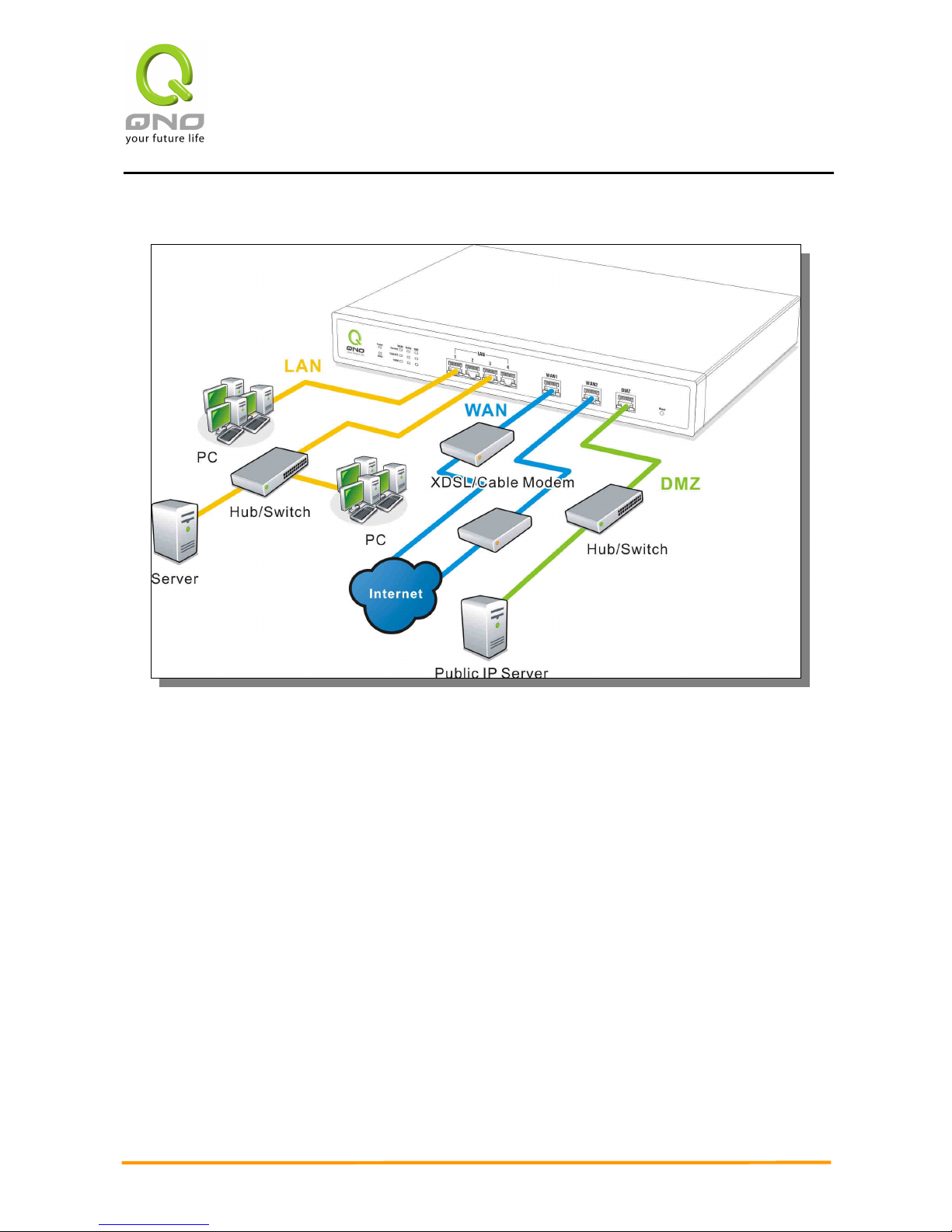
WAN connection : A WAN port can be connected with xDSL Modem, Fiber Modem,
Switching Hub, or through an external router to connect to the Internet.
LAN Connection: The LAN port can be connected to a Switching Hub or directly to a PC.
Users can use servers for monitoring or filtering through the port after “Physical Port
Mangement” configuration is done.
DMZ : The DMZ port can be connected to servers that have legal IP addresses, such as Web
servers, mail servers, etc.
Page 16
Enterprise Multi-WAN VPN QoS Router
9
IV. Login
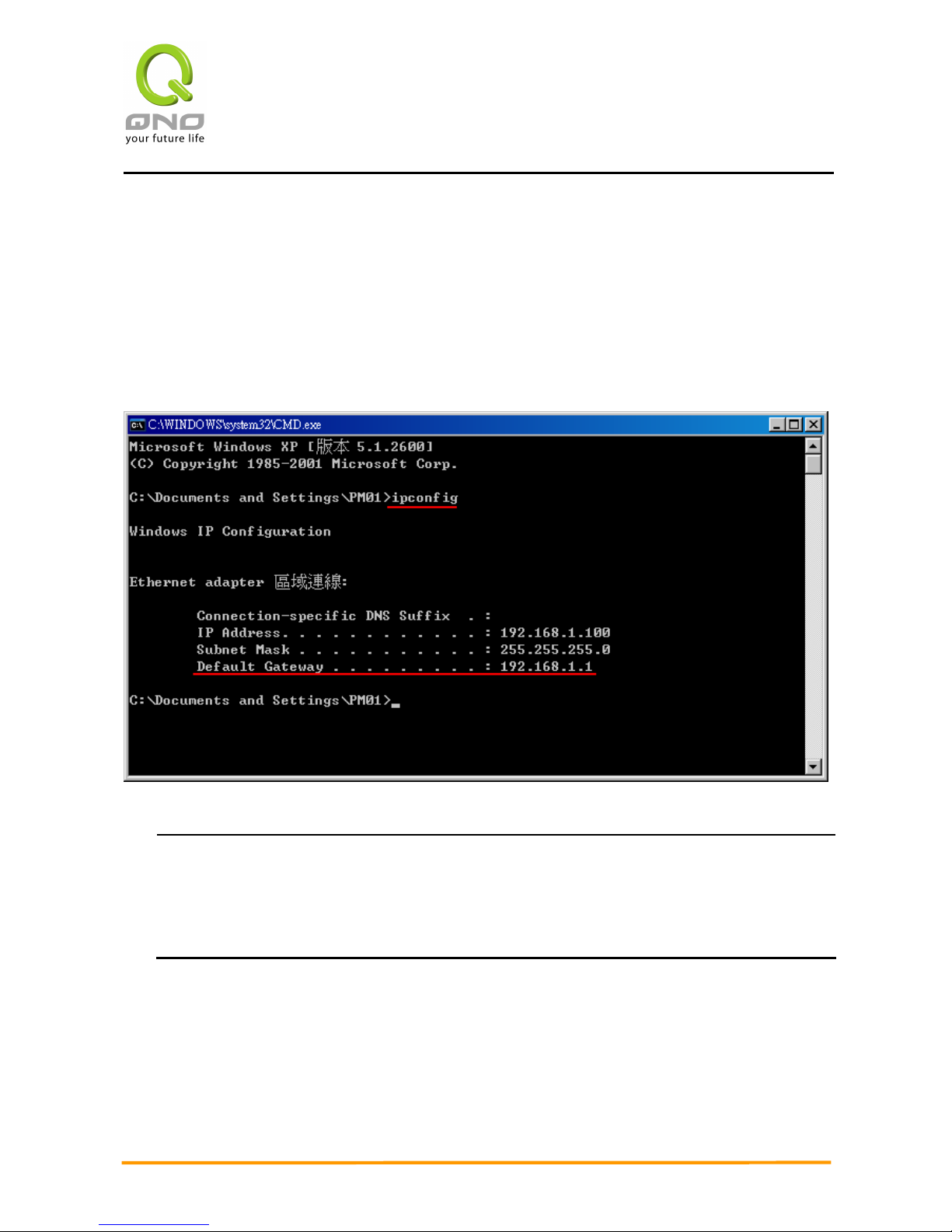
This chapter is mainly introducing Web- based UI after conneting the device.
First, check up the device’s IP address by connecting to DOS through the LAN PC under the
device. Go to Start Run, enter cmd to commend DOS, and enter ipconfig for getting Default →
Gateway address, as the graphic below, 192.168.1.1. Make sure Default Gateway is also the
default IP address of the router.
Attention!
When not getting IP address and default gateway by using “ipconfig”, or the received IP
address is 0.0.0.0 and 169.X.X.X, we recommend that users should check if there is any
problem with the circuits or the computer network card is connected nicely.
Page 17
Enterprise Multi-WAN VPN QoS Router
10
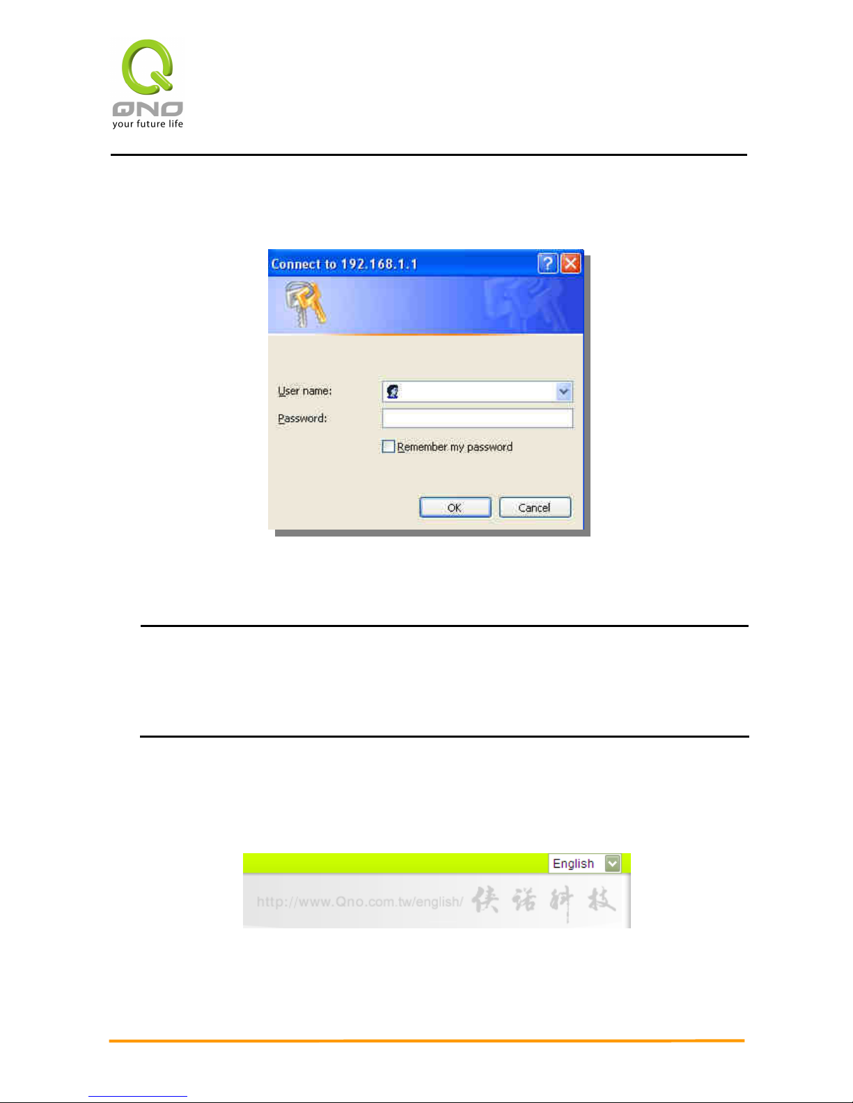
Then, open webpage browser, IE for example, and key in 192.168.1.1 in the website column.
The login window will appear as below:
The device’s default username and password are both “admin”. Users can change the login
password in the setting later.
Attention!
For security, we strongly suggest that users must change password after login. Please
keep the password safe, or you can not login to the device. Press Reset button for more
than 10 sec, all the setting will return to default.
After login, the device’s web- based UI will be shown. Select the language on the upper right
corner of the webpage. The language chosen will be in blue. Please select “English’ as below.
Page 18
Enterprise Multi-WAN VPN QoS Router
11
V. Device Spec Verification, Status Display and Login Password and Time Setting
This chapter introduces the device specification and status after login as well as change
password and system time settings for security.
5.1 Home Page
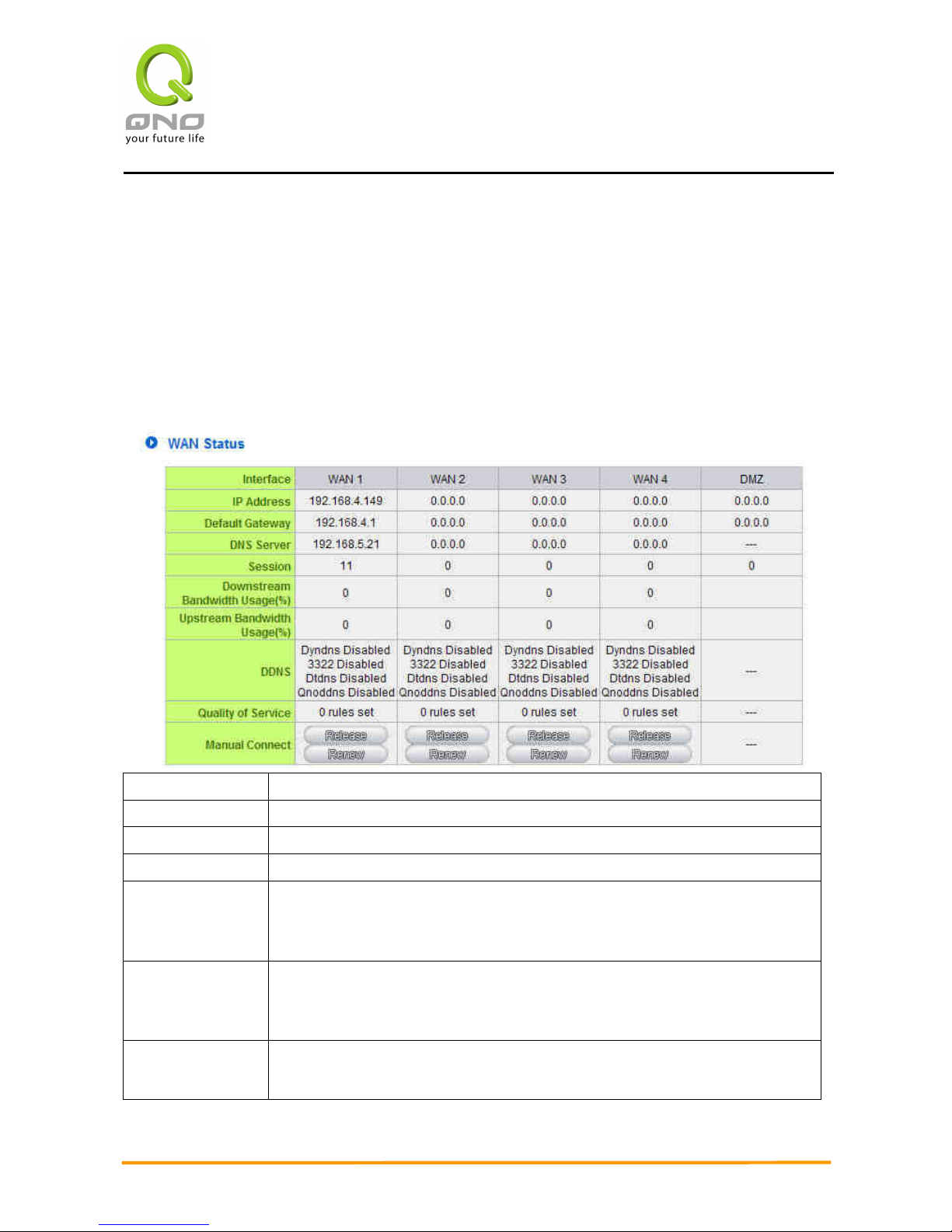
In the Home page, all the device’s parameters and status are listed for users’ reference.
5.1.1 WAN Status
IP Address:
Indicates the current IP configuration for WAN port.
Default Gateway:
Indicates current WAN gateway IP address from ISP.
DNS Server:
Indicates the current DNS IP configuration.
Session:
Indicates the current session number for each WAN in the device.
Downstream
Bandwidth
Usage(%):
Indicates the current downstream bandwidth usage(%) for each WAN.
Upstream
Bandwidth
Usage(%):
Indicates the current upstream bandwidth usage(%) for each WAN.
DDNS:
Indicates if Dynamic Domain Name is activated. The default
configuration is “Off”.
Page 19
Enterprise Multi-WAN VPN QoS Router
12
Quality of
Service:
Indicates how many QoS rules are set.
Manual Connect:
When “Obtain an IP automatically” is selected, two buttons (Release
and Renew) will appear. If a WAN connection, such as PPPoE or PPTP, is
selected, “Disconnect” and “Connect” will appear.
DMZ IP Address:
Indicates the current DMZ IP address.
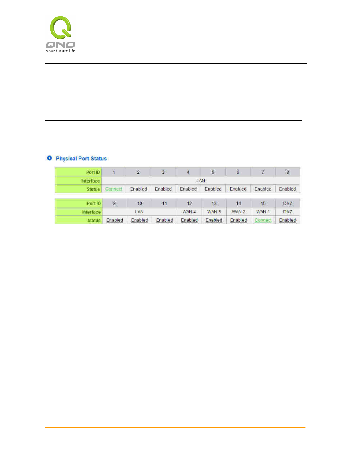
5.1.2 Physical Port Status
The status of all system ports, including each connected and enabled port, will be shown
on this Home page (see above table). Click the respective status button and a separate
window will appeare to show detailed data (including setting status summary and statisitcs)
of the selected port.
Page 20
Enterprise Multi-WAN VPN QoS Router
13
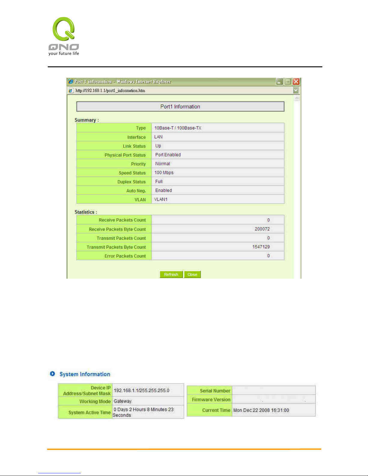
The current port setting status information will be shown in the Port Information Table.
Examples: type (10Base-T/100Base-TX/1000Base-T), iniferface (WAN/ LAN/ DMZ), link status
(Up/ Down), physical port status (Port Enabled/ Port Disabled), priority (high or normal), speed
status (10Mbps or 100Mbps), duplex status (Half/ Full), auto negotiation (Enabled or Disabled).
The tabble also shows statistics of Receive/ Transmit Packets, Receive/Transmit Packets Byte
Count as well as Error Packets Count.
5.1.3 System Information
Page 21
Enterprise Multi-WAN VPN QoS Router
14
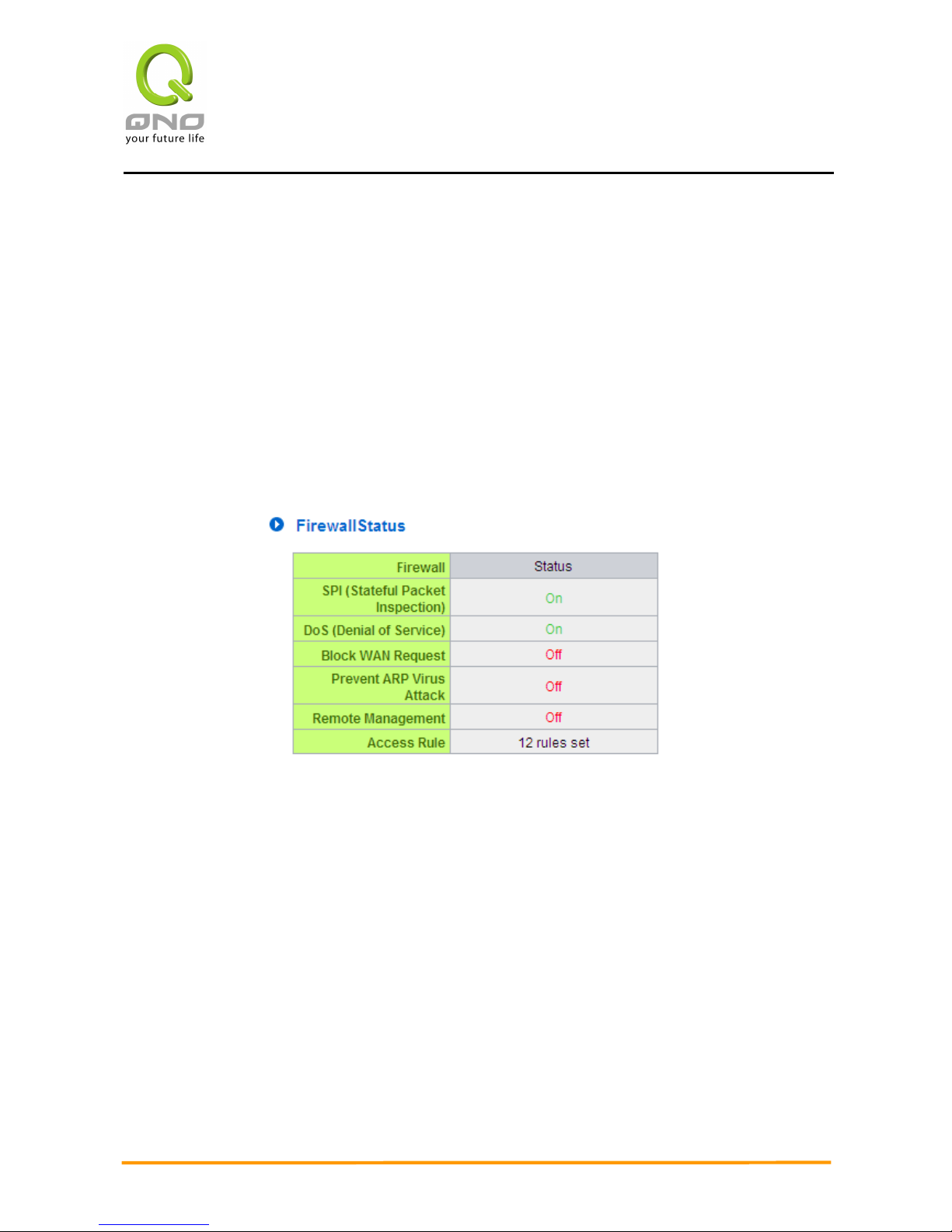
Device IP Address/ Subnet Mask:Identifies the current device IP address and subnet
mask. The default is 192.168.1.1 and 255.255.255.0
Working Mode:Indicates the current working mode. Can be Gateway or Router mode. The
default is “Gateway” mode.
System active time: Indicates how long the device has been running.
Serial Number: This number is the device serial number.
Firmware Version:Information about the device present software version.
Current Time: Indicates the device present time
. Please note:
To have the correct time,
users must synchronize the device with the remote NTP server first.
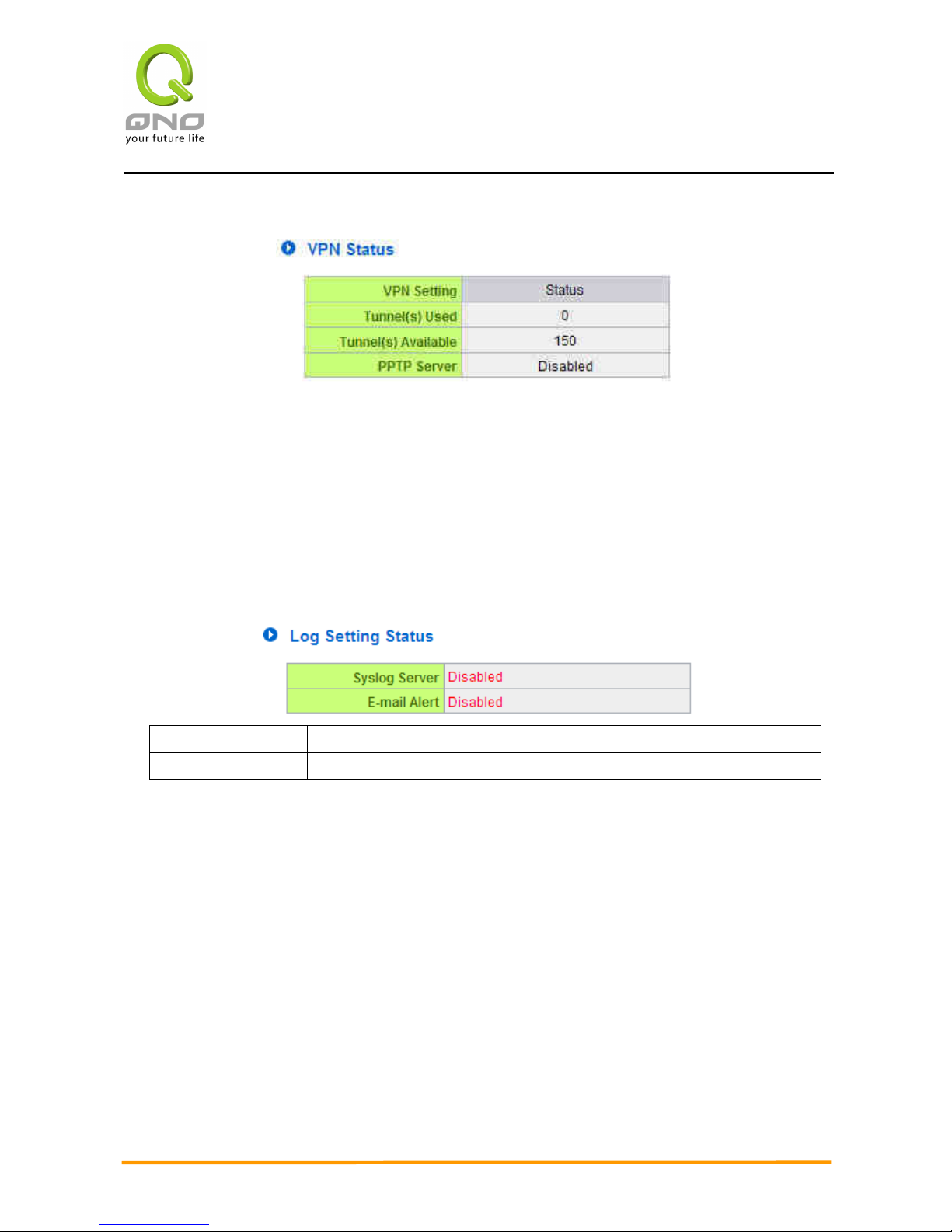
5.1.4 Firewall Status
SPI (Stateful Packet Inspection): Indicates whether SPI (Stateful Packet Inspection) is
on or off. The default configuration is “On”.
DoS (Denial of Service):Indicates if DoS attack prevention is activated. The default
configuration is “On”.
Block WAN Request:Indicates that denying the connection from Internet is activated. The
default configuration is “On”.
Prevent ARP Virus Attack:Indicates that preventing Arp virus attack is acitvated. The
default configuration is “Off”.
Remote Management: Indicates if remote management is activated (on or off). Click the
hyperlink to enter and manage the configuration. The default configuration is “Off”.
Access Rule:Indicates the number of access rule applied in the device.
Page 22
Enterprise Multi-WAN VPN QoS Router
15
5.1.5 VPN Status
VPN Setting Status: Indicates VPN setting information in the device.
Tunnel(s) Used:Indicates number of tunnels that have been configured in VPN (Virtual
Private Network).
Tunnel(s) Available:Indicates number of tunnels that are available for VPN (Virtual Private
Network).
PPTP Server:Indicates if PPTP server is enabled.
5.1.6 Log Setting Status
Syslog Server:
Indicates if Syslog Server is Enabled or Disabled.
E-mail Alert:
Indicates if Email Alert is Enabled or Disabled.
Page 23
Enterprise Multi-WAN VPN QoS Router
16
5.2 Change and Set Login Password and Time
5.2.1 Password Setting
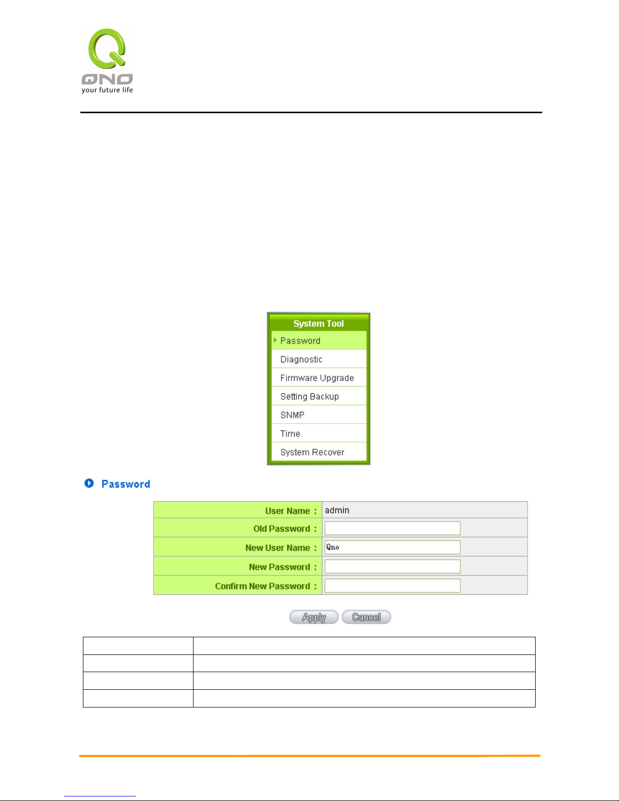
When you login the device setting window every time, you must enter the password. The
default value for the device username and password are both “admin”. For security reasons,
we strongly recommend that you must change your password after first login. Please keep the
password safe, or you might not login to the device. You can press Reset button for more than
10 sec, the device will return back to default.
User Name:
The default is “admin”.
Old Password: Input the original password.(The default is “admin”.)
New User Name:
Input the new user name. i.e.Qno
New Password:
Input the new password.
Page 24
Enterprise Multi-WAN VPN QoS Router
17
Confirm New
Password:
Input the new password again for verification.
Apply:
Click “Apply” to save the configuration.
Cancel:
Click “Cancel" to leave without making any change. This action will be
effective before ”Apply” to save the configuration.
5.2.2 Time
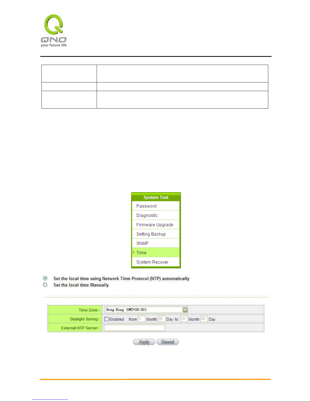
The device can adjust time setting. Users can know the exact time of event occurrences that
are recorded in the System Log, and the time of closing or opening access for Internet resources.
You can either select the embedded NTP Server synchronization function or set up a time
reference.
Synchronize with external NTP server:The device has embedded NTP server, which will update
the time spontaneously.
Page 25
Enterprise Multi-WAN VPN QoS Router
18
Time Zone:
Select your location from the pull-down time zone list to show
correct local time.
Daylight Saving:
If there is Daylight Saving Time in your area, input the date
range. The device will adjust the time for the Daylight Saving
period automatically.
External NTP Server:
If you have your own preferred time server, input the server IP
address.
Apply:
After the changes are completed, click “Apply” to save the
configuration.
Cancel:
Click “Cancel" to leave without making any change. This action
will be effective before ”Apply” to save the configuration.
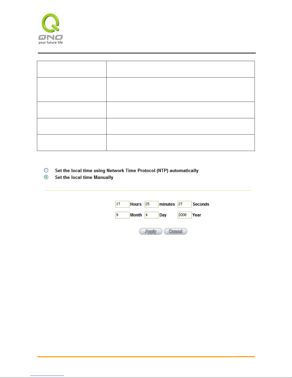
Select the Local Time Manually: Input the correct time, date, and year in the boxes.
After the changes are completed, click “Apply” to save the configuration. Click “Cancel" to
leave without making any change. This action will be effective before ”Apply” to save the
configuration.
Page 26
Enterprise Multi-WAN VPN QoS Router
19
VI. Network
This Network page contains the basic settings. For most users, completing this general
setting is enough for connecting with the Internet. However, some users need advanced
information from their ISP. Please refer to the following descriptions for specific configurations.
6.1 Network Connection
Page 27
Enterprise Multi-WAN VPN QoS Router
20
6.1.1 Host Name and Domain Name
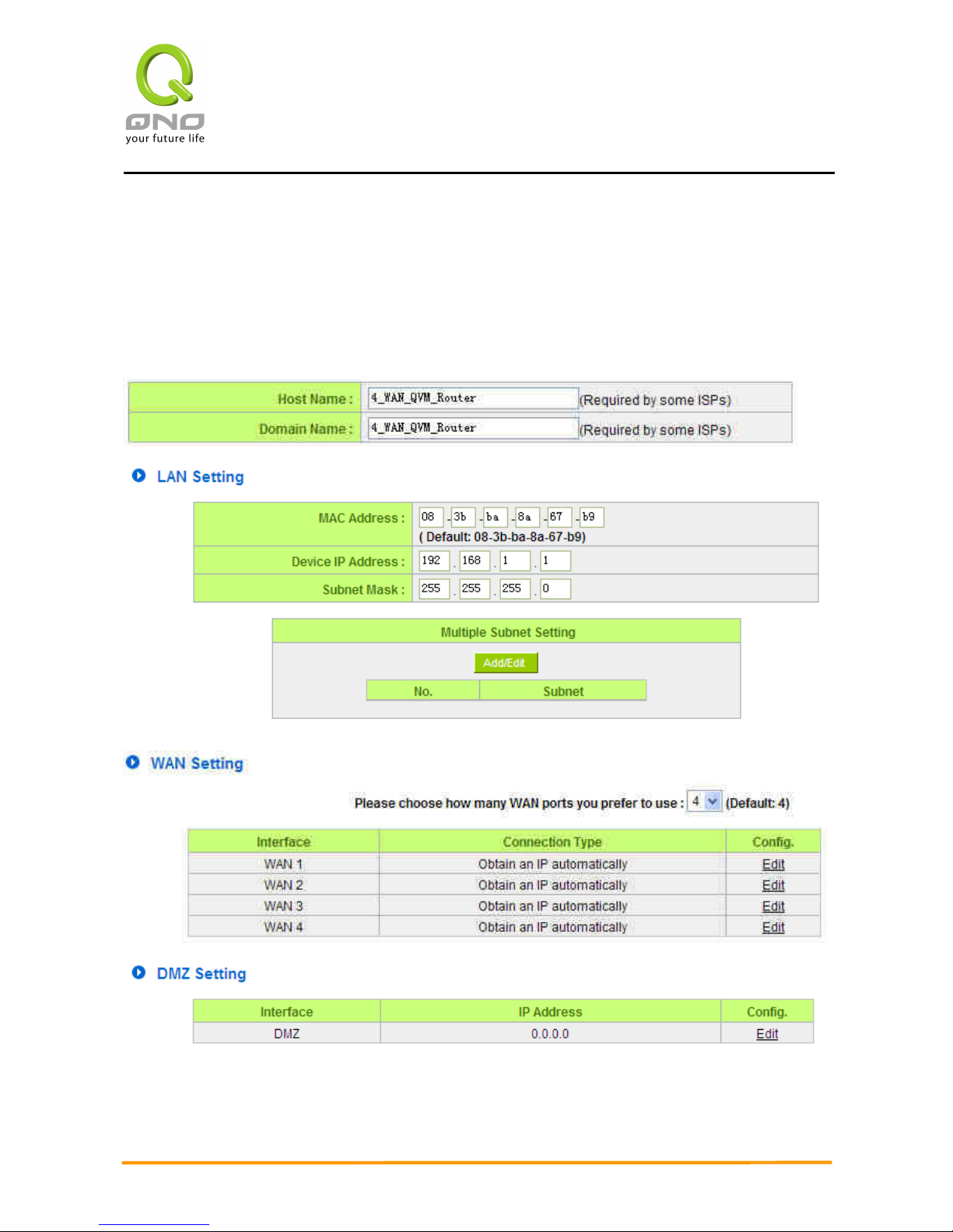
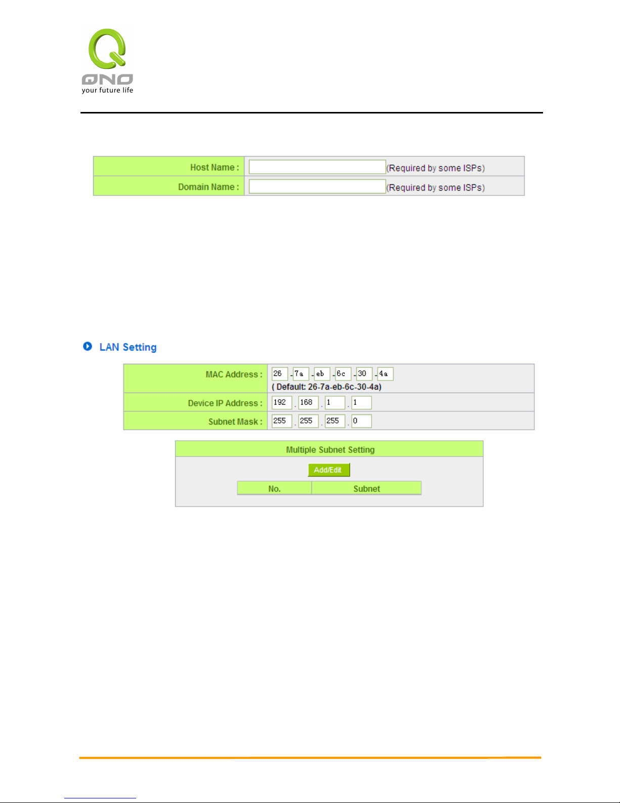
Device name and domain name can be input in the two boxes. Though this configuration is
not necessary in most environments, some ISPs in some countries may require it.
6.1.2 LAN Setting
This is configuration information for the device current LAN IP address. The default
configuration is 192.168.1.1 and the default Subnet Mask is 255.255.255.0. It can be
changed according to the actual network structure.
Multiple-Subnet Setting:
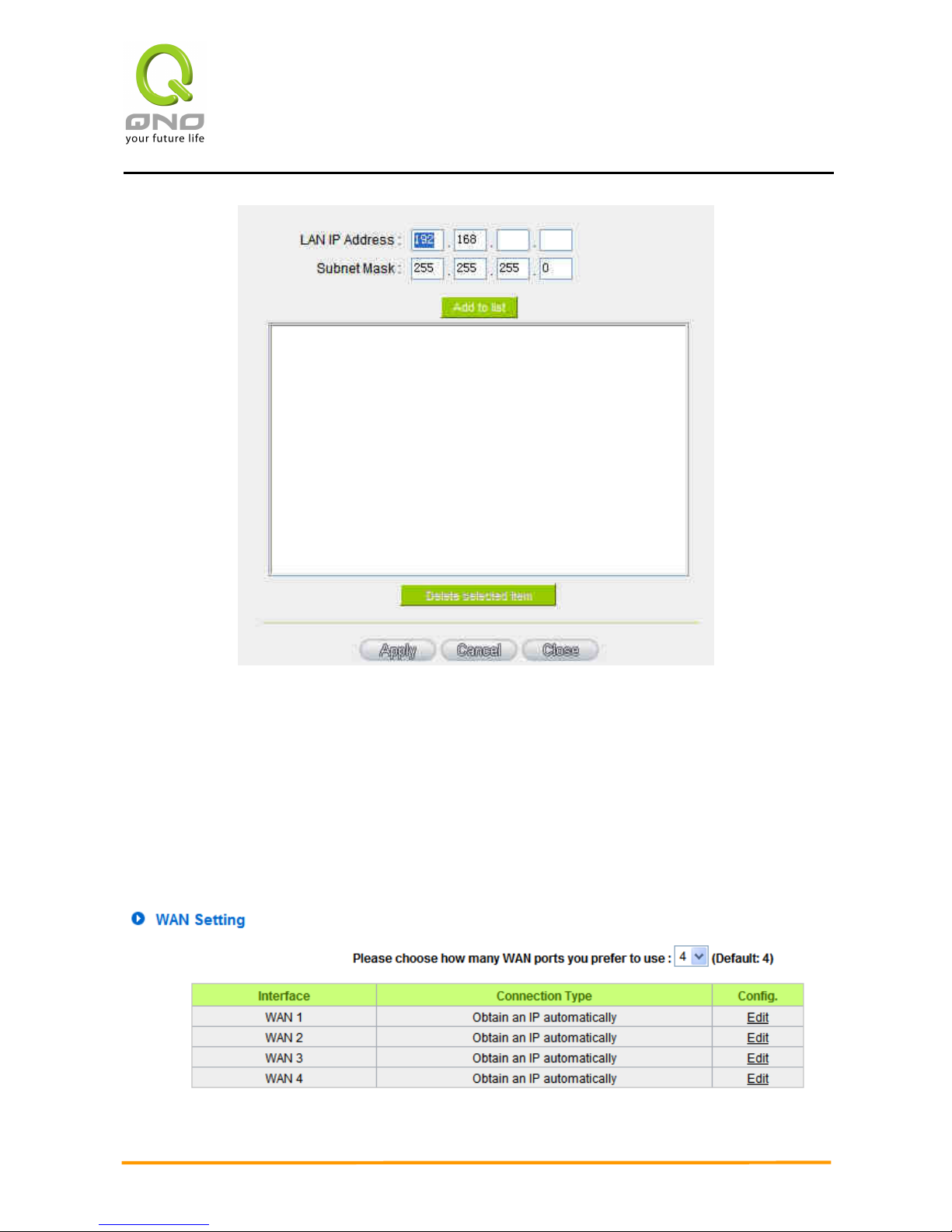
Click “Add/Edit” to enter the configuration page, as shown in the following figure. Input the
respective IP addresses and subnet masks.
Page 28
Enterprise Multi-WAN VPN QoS Router
21
This function enables users to input IP segments that differ from the router network
segment to the multi-net segment configuration; the Internet will then be directly accessible.
In other words, if there are already different IP segment groups in the Intranet, the Internet
is still accessible without making any changes to internal PCs. Users can make changes
according to their actual network structure.
6.1.3 WAN & DMZ Settings
WAN Setting:
Page 29
Enterprise Multi-WAN VPN QoS Router
22
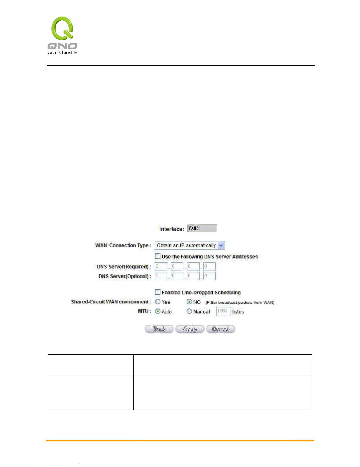
Interface: An indication of which port is connected.
Connection Type: Obtain an IP automatically, Static IP connection, PPPoE (Point-to-Point
Protocol over Ethernet), PPTP (Point-to-Point Tunneling Protocol) or Transparent Bridge.
Config.: A modification in an advanced configuration: Click Edit to enter the advanced
configuration page.
Obtain an Automatic IP automatically:
This mode is often used in the connection mode to obtain an automatic DHCP IP. This is
the device system default connection mode. It is a connection mode in which DHCP clients obtain
an IP address automatically. If having a different connection mode, please refer to the following
introduction for selection of appropriate configurations. Users can also set up their own DNS IP
address. Check the options and input the user-defined DNS IP addresses.
Use the following DNS
Server Addresses:
Select a user-defined DNS server IP address.
DNS Server: Input the DNS IP address set by ISP. At least one IP group
should be input. The maximum acceptable groups is two IP
groups.
Page 30

Enterprise Multi-WAN VPN QoS Router
23
Enable Line-Dropped
Scheduling:
The WAN disconnection schedule will be activated by checking
this option. In some areas, there is a time limitation for WAN
connection service. For example: the optical fiber service will be
disconnected from 0:00 am to 6:00 am. Although there is a
standby system in the device, at the moment of WAN
disconnection
, all the external connections that go through this
WAN will be disconnected too. Only after the disconnected
lines
are reconnected can they go through the standby system to
connect with the Internet. Therefore, to avoid a huge number of
disconnection, users can activate this function to arrange new
connections to be made through another WAN to the Internet. In
this way, the effect of any disconnection can be minimized.
Line-Dropped Period Input the time rule for disconnection of this WAN service.
Line-Dropped Scheduling Input how long the WAN service may be disconnected
before the
newly added connections should go through another WAN to
connect with the Internet.
Link Backup Interface Select another WAN port as link backup when port binding is
configured. Users should select the port that employs the same
ISP.
Shared- Circuit WAN
environment
If your WAN connects to a Switch, select “Enabled” to filter
broadcast packets. The default is “Disabled”.
MTU::::
MTU is abbreviation of Maximum Transmission Unit. “Auto” and
“Manual” can be chosen. The default value is 1500. Different
value could be set in different network environment. (e.g. ADSL
PPPoE MTU: 1492)
The default is “Auto”.
After the changes are completed, click “Apply” to save the configuration, or click “Cancel"
to leave without making any changes.
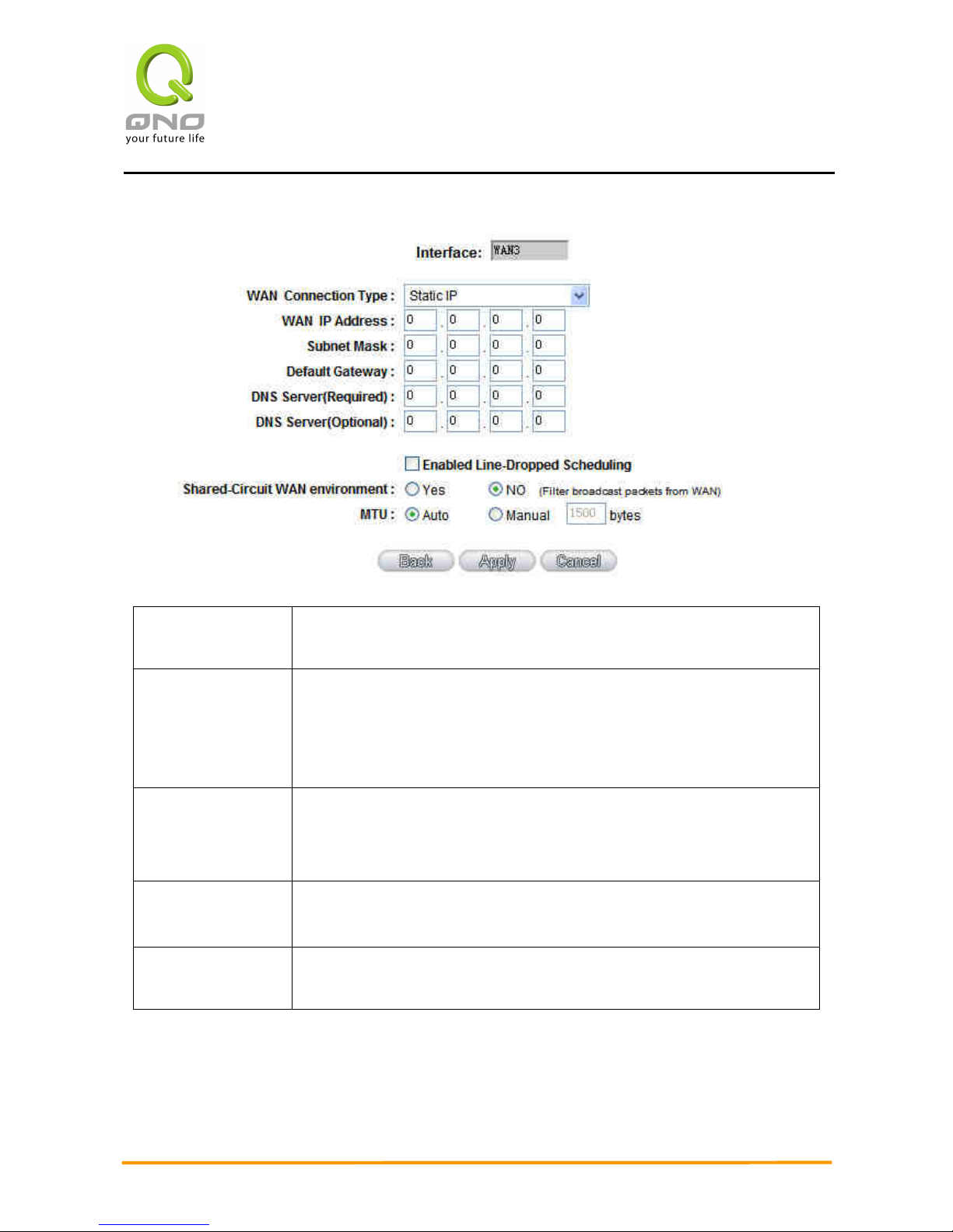
Static IP
If an ISP issues a static IP (such as one IP or eight IP addresses, etc.), please select this
connection mode and follow the steps below to input the IP numbers issued by an ISP into the
relevant boxes.
Page 31
Enterprise Multi-WAN VPN QoS Router
24
WAN IP
address:
Input the available static IP address issued by ISP.
Subnet Mask: Input the subnet mask of the static IP address issued by ISP, such as:
Issued eight static IP addresses: 255.255.255.248
Issued 16 static IP addresses: 255.255.255.240
Default
Gateway:
Input the default gateway issued by ISP. For ADSL users, it is usually
an ATU-R IP address. As for optical fiber users, please input the
optical fiber switching IP.
DNS Server: Input the DNS IP address issued by ISP. At least one IP group should
be input. The maximum acceptable is two IP groups.
WAN IP
address:
Input the available static IP address issued by ISP.
Page 32

Enterprise Multi-WAN VPN QoS Router
25
Enable
Line-Dropped
Scheduling:
The WAN disconnection schedule will be activated by checking this
option. In some areas, there is a time limitation for WAN connection
service. For example: the optical fiber service will be disconnected
from 0:00 am to 6:00 am. Although there is a standby system in the
device, at the moment of WAN disconnection, all the external
connections that go through this WAN will be disconnected too. Only
after the disconnected lines are reconnected can they go through the
standby system to connect with the Internet. Therefore, to avoid a
huge number of disconnections, users can activate this function to
arrange new connections to be made through another WAN to the
Internet. In this way, the effect of any disconnection can be
minimized.
Line-Dropped
Period
Input the time rule for the disconnection of this WAN service.
Line-Dropped
Scheduling
Input how long the WAN service may be disconnected before the
newly added connections should go through another WAN to connect
with the Internet.
WAN IP
address:
Input the available static IP address issued by ISP.
Shared- Circuit
WAN
environment
If your WAN connects to a Switch, select “Enabled” to filter broadcast
packets. The default is “Disabled”.
After the changes are completed, click “Apply” to save the configuration, or click “Cancel"
to leave without making any changes.
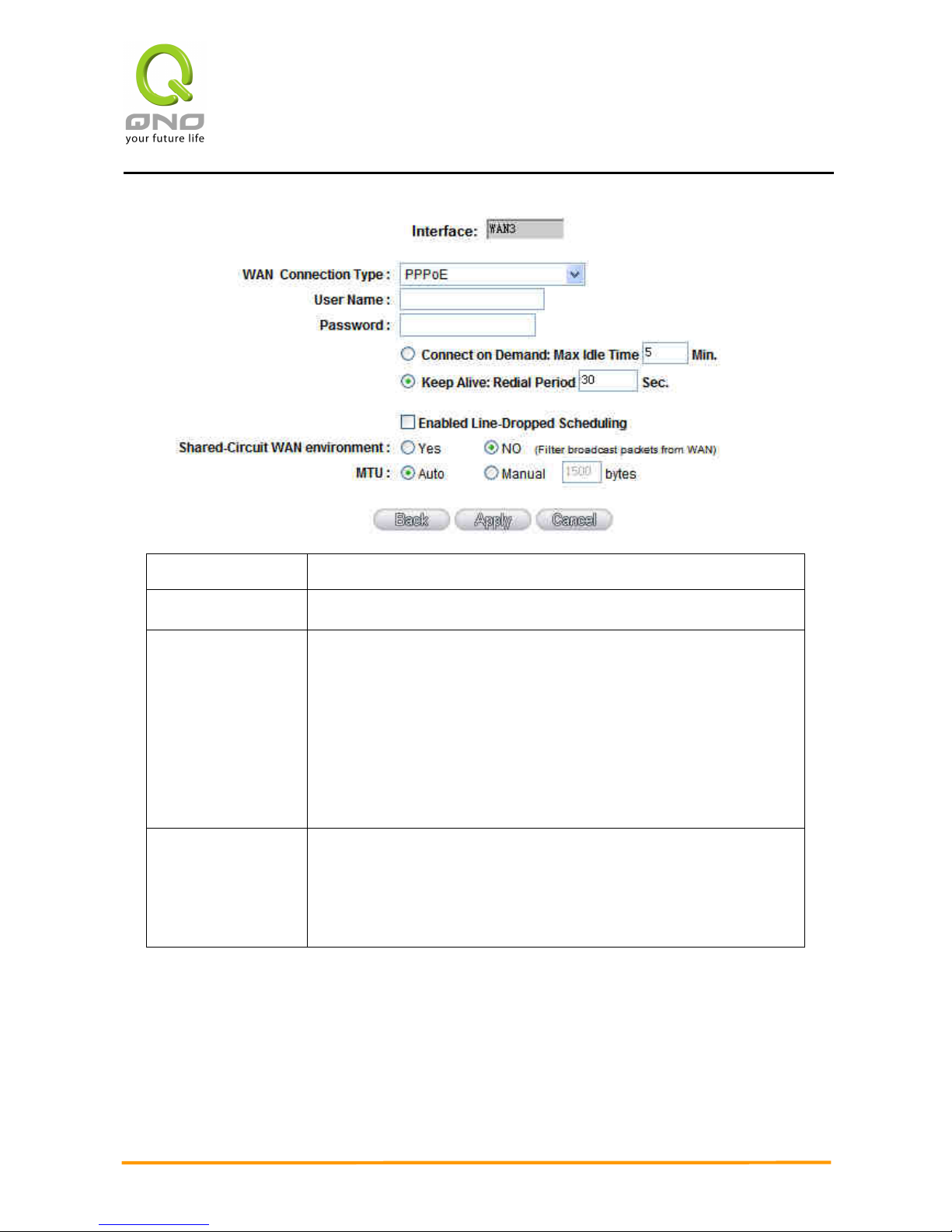
PPPoE
This option is for an ADSL virtual dial-up connection (suitable for ADSL PPPoE). Input the user
connection name and password issued by ISP. Then use the PPP Over-Ethernet software built into
the device to connect with the Internet. If the PC has been installed with the PPPoE dialing
software provided by ISP, remove it. This software will no longer be used for network connection.
Page 33
Enterprise Multi-WAN VPN QoS Router
26
User Name: Input the user name issued by ISP.
Password Input the password issued by ISP.
Connect on
Demand:
This function enables the auto-dialing function to be used in a
PPPoE dial connection. When the client port attempts to connect
with the Internet, the device will automatically make a dial
connection. If the line has been idle for a period of time, the
system will break the connection automatically. (The default time
for automatic break-off resulting from no packet transmissions is
five minutes).
Keep Alive: This function enables the PPPoE dial connection to keep
connected, and to automatically redial if the line is disconnected.
It also enables a user to set up a time for redialing. The default is
30 seconds.
Page 34

Enterprise Multi-WAN VPN QoS Router
27
Enable
Line-Dropped
Scheduling
The WAN disconnection schedule will be activated by checking
this option. In some areas, there is a time limitation for WAN
connection service. For example: the optical fiber service will be
disconnected from 0:00 am to 6:00 am. Although there is a
standby system in the device, at the moment of WAN
disconnection, all the external connections that go through this
WAN will be disconnected too. Only after the disconnected lines
are reconnected can they go through the standby system to
connect with the Internet. Therefore, to avoid a huge number of
disconnections, users can activate this function to arrange new
connections through another WAN to the Internet. In this way,
the effect of any disconnection can be minimized.
Line-Dropped
Period
Input the time rule for the disconnection of this WAN service.
Line-Dropped
Scheduling
Input how long the WAN service may be disconnected before the
newly added connections should go through another WAN to
connect with the Internet.
Link Backup
Interface
Select another WAN port as link backup when port binding is
configured. Users should select the port that employs the same
ISP.
Shared- Circuit
WAN
environment
If your WAN connects to a Switch, select “Enabled” to filter
broadcast packets. The default is “Disabled”.
MTU::::
MTU is abbreviation of Maximum Transmission Unit. “Auto” and
“Manual” can be chosen. The default value is 1500. Different value
could be set in different network environment. (e.g. ADSL PPPoE
MTU: 1492)
The default is “Auto”.
After the changes are completed, click “Apply” to save the configuration, or click “Cancel"
to leave without making any change.
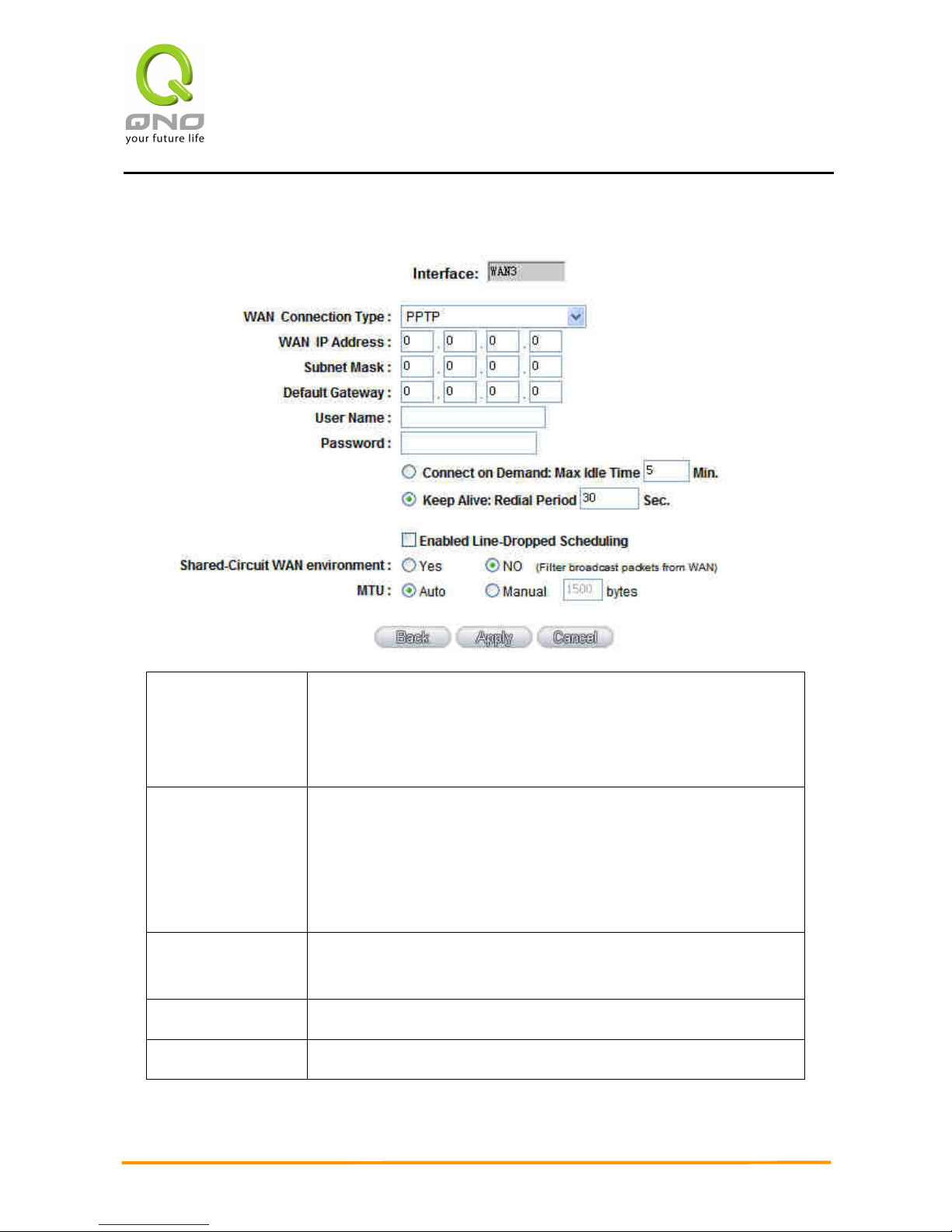
PPTP
This option is for the PPTP time counting system. Input the user’s connection name and
Page 35
Enterprise Multi-WAN VPN QoS Router
28
password issued by ISP, and use the built-in PPTP software to connect with the Internet.
WAN IP
Address:
This option is to configure a static IP address. The IP address to
be configured could be one issued by ISP. (The IP address is
usually provided by the ISP when the PC is installed. Contact ISP
for relevant information).
Subnet Mask: Input the subnet mask of the static IP address issued by ISP, such
as:
Issued eight static IP addresses: 255.255.255.248
Issued 16 static IP addresses: 255.255.255.240
Default Gateway
Address:
Input the default gateway of the static IP address issued by ISP.
For ADSL users, it is usually an ATU-R IP address.
User Name: Input the user name issued by ISP.
Password: Input the password issued by ISP.
Page 36

Enterprise Multi-WAN VPN QoS Router
29
Connect on
Demand:
This function enables the auto-dialing function to be used for a
PPTP dial connection. When the client port attempts to connect
with the Internet, the device will automatically connect with the
default ISP auto dial connection; when the network has been idle
for a period of time, the system will break the connection
automatically. (The default time for automatic break off when no
packets have been transmitted is five minutes).
Keep Alive: This function enables the PPTP dial connection to redial
automatically when the connection has been disconnected. Users
can set up the redialing time. The default is 30 seconds.
Enable
Line-Dropped
Scheduling
The WAN disconnection schedule will be activated by checking
this option. In some areas, there is a time limitation for WAN
connection service. For example: the optical fiber service will be
disconnected from 0:00 am to 6:00 am. Although there is a
standby system in the device, at the moment of WAN
disconnection, all the external connections that go through this
WAN will be disconnected too. Only after the disconnected lines
are reconnected can they go through the standby system to
connect with the Internet. Therefore, to avoid a huge number of
disconnection, users can activate this function to arrange new
connections to be made through another WAN to the Internet. In
this way, the effect of any disconnection can be minimized.
Line-Dropped
Period
Input the time rule for the disconnection of this WAN service.
Line-Dropped
Scheduling
Input how long the WAN service may be disconnected before the
newly added connections should go through another WAN to
connect with the Internet.
Link Backup
Interface
Select another WAN port as link backup when port binding is
configured. Users should select the port that employs the same
ISP.
Page 37

Enterprise Multi-WAN VPN QoS Router
30
Shared- Circuit
WAN
environment
If your WAN connects to a Switch, select “Enabled” to filter
broadcast packets. The default is “Disabled”.
MTU::::
MTU is abbreviation of Maximum Transmission Unit. “Auto” and
“Manual” can be chosen. The default value is 1500. Different value
could be set in different network environment. (e.g. ADSL PPPoE
MTU: 1492)
The default is “Auto”.
After the changes are completed, click “Apply” to save the configuration, or click “Cancel"
to leave without making any changes.
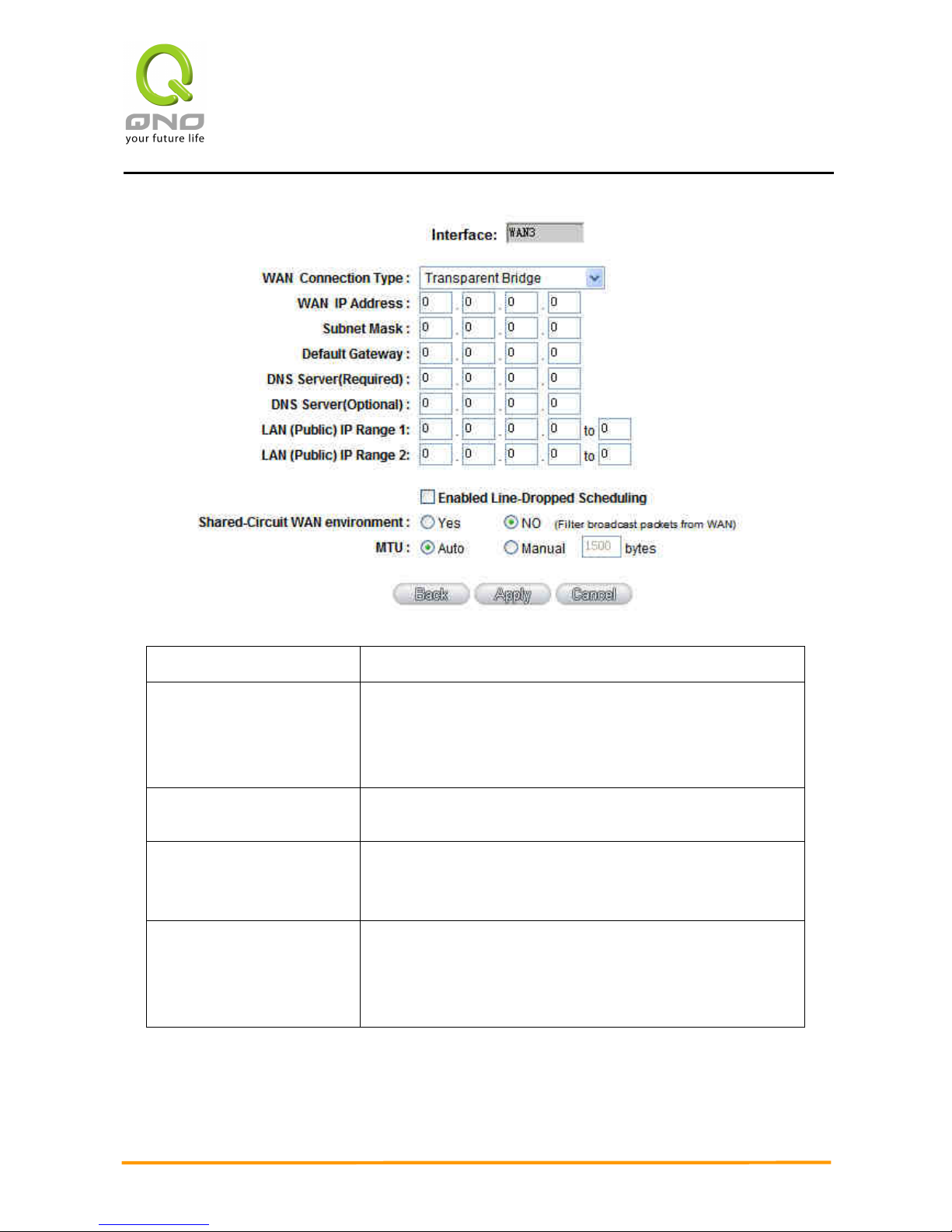
Transparent Bridge
If all Intranet IP addresses are applied as Internet IP addresses, and users don’t want to
substitute private network IP addresses for all Intranet IP addresses (ex. 192.168.1.X), this
function will enable users to integrate existing networks without changing the original structure.
Select the Transparent Bridge mode for the WAN connection mode. In this way, users will be able
to connect normally with the Internet while keeping the original Internet IP addresses in Intranet
IP configuration.
If there are two WANs configured, users still can select Transparent Bridge mode for WAN
connection mode, and load balancing will be achieved as usual.
Page 38
Enterprise Multi-WAN VPN QoS Router
31
WAN IP Address: Input one of the static IP addresses issued by ISP.
Subnet Mask:
Input the subnet mask of the static IP address issued by
ISP, such as:
Issued eight static IP addresses: 255.255.255.248
Issued 16 static IP addresses: 255.255.255.240
Default Gateway Address:
Input the default gateway of the static IP address issued
by ISP. For ADSL users, it is usually an ATU-R IP address.
DNS Server:
Input the DNS IP address set by ISP. At least one IP group
should be input. The maximum acceptable is two IP
groups.
Internal LAN IP Range:
Input the available IP range issued by ISP. If ISP issued
two discontinuous IP address ranges, users can input
them into Internal LAN IP Range 1 and Internal LAN
IP Range 2 respectively.
Page 39

Enterprise Multi-WAN VPN QoS Router
32
Enable Line-Dropped
Scheduling:
The WAN disconnection schedule will be activated by
checking this option. In some areas, there is a time
limitation for WAN connection service. For example: the
optical fiber service will be disconnected from 0:00 am to
6:00 am. Although there is a standby system in the
device, at the moment of WAN disconnection, all the
external connections that go through this WAN will be
disconnected too. Only after the disconnected lines are
reconnected can they go through the standby system to
connect with the Internet. Therefore, to avoid a huge
number of disconnections, users can activate this function
to arrange new connections through another WAN to the
Internet. In this way, the effect of any disconnection can
be minimized.
Line-Dropped Period:
Input the time rule for the disconnection of this WAN
service.
Line-Dropped
Scheduling:
Input how long the WAN service may be disconnected
before the newly added connections should go through
another WAN to connect with the Internet.
Link Backup Interface:
Select another WAN port as link backup when port binding
is configured. Users should select the port that employs the
same ISP.
Shared- Circuit WAN
environment:
If your WAN connects to a Switch, select “Enabled” to filter
broadcast packets. The default is “Disabled”.
MTU:
MTU is abbreviation of Maximum Transmission Unit. “Auto”
and “Manual” can be chosen. The default value is 1500.
Different value could be set in different network
environment. (e.g. ADSL PPPoE MTU: 1492)
The default is “Auto”.
After the changes are completed, click “Apply” to save the configuration, or click “Cancel"
to leave without making any changes.
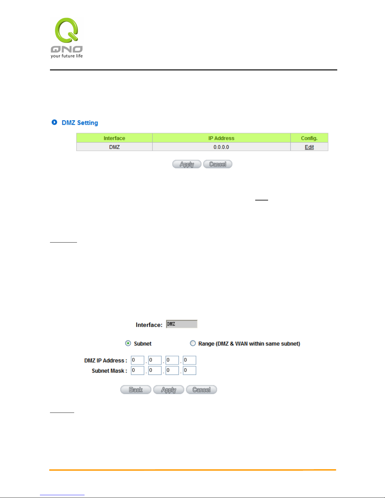
DMZ Setting
For some network environments, an independent DMZ port may be required to set up
Page 40
Enterprise Multi-WAN VPN QoS Router
33
externally connected servers such as WEB and Mail servers. Therefore, the device supports a set
of independent DMZ ports for users to set up connections for servers with real IP addresses. The
DMZ ports act as bridges between the Internet and LANs.
IP address: Indicates the current default static IP address.
Config.: Indicates an advanced configuration modification: Click Edit to enter the advanced
configuration page.
The DMZ configuration can be classified by Subnet and Range:
Subnet:
The DMZ and WAN located in different Subnets
For example: If the ISP issued 16 real IP addresses: 220.243.230.1-16 with Mask
255.255.255.240, users have to separate the 16 IP addresses into two groups: 220.243.230.1-8
with Mask 255.255.255.248, and 220.243.230.9-16 with Mask 255.255.255.248 and then set the
device and the gateway in the same group with the other group in the DMZ.
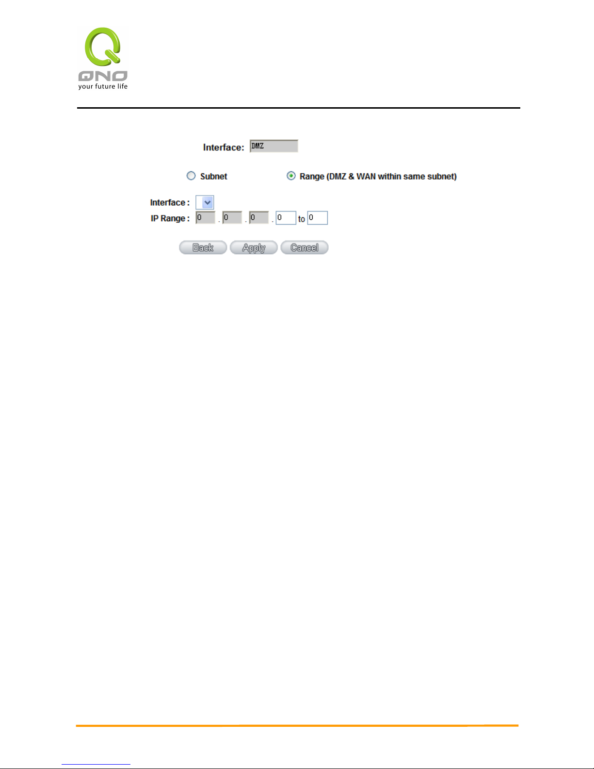
Range:
DMZ and WAN within same Subnet
Page 41
Enterprise Multi-WAN VPN QoS Router
34
IP Range: Input the IP range located at the DMZ port.
After the changes are completed, click “Apply” to save the configuration, or click “Cancel"
to leave without making any changes.
Page 42
Enterprise Multi-WAN VPN QoS Router
35
6.2 Multi- WAN Setting
6.2.1 Load Balance Mode
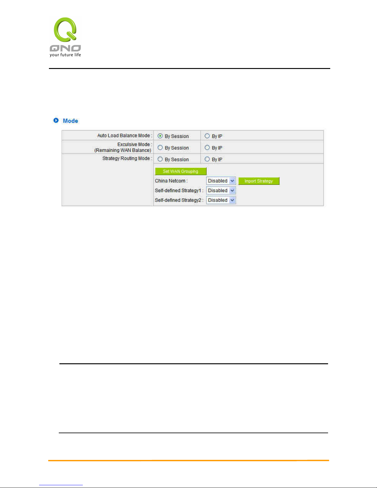
Auto Load Balance Mode
When Auto Load Balance mode is selected, the device will use sessions or IP and the WAN
bandwidth automatically allocate connections to achieve load balancing for external connections.
The network bandwidth is set by what users input for it. For example, if the upload bandwidth of
both WANs is 512Kbit/sec, the automatic load ratio will be 1:1; if one of the upload bandwidths is
1024Kbit/sec while the other is 512Kbit/sec, the automatic load ratio will be 2:1. Therefore, to
ensure that the device can balance the actual network load, please input real upload and
download bandwidths.
Session Balance: If “By Session” is selected, the WAN bandwidth will
automatically allocate connections based on session number to achieve network
load balance.
IP Session Balance: If “By IP” is selected, the WAN bandwidth will automatically
allocate connections based on IP amount to achieve network load balance.
Note!
For either session balancing or IP connection balancing, collocation with Protocol
Binding will provide a more flexible application for bandwidth. Users can assign a
specific Intranet IP to go through a specific service provider for connection, or assign an
IP for a specific destination to go through the WAN users assign to connect with the
Internet.
Page 43

Enterprise Multi-WAN VPN QoS Router
36
For example, if users want to assign IP 192.168.1.100 to go through WAN 1 when
connecting with the Internet, or assign all Intranet IP to go through WAN 2 when
connecting with servers with port 80, or assign all Intranet IP to go through WAN 1
when connecting with IP 211.1.1.1, users can do that by configuring “Protocol Binding”.
Attention! When the Auto Load Balance mode is collocated with Protocol Binding, only IP
addresses or servers that are configured in the connection rule will follow the rule for
external connections; those which are not configured in the rule will still follow the device
Auto Load Balance system.
Please refer to the explanations in 6.2.3 Configuring Protocol Binding for setting up
Protocol Binding and for examples of collocating router modes with Protocol Binding.
Exclusive Mode
This mode enables users to assign specific intranet IP addresses, destination
application service ports or destination IP addresses to go through an assigned WAN for
external connection. After being assigned, the specific WAN will only support those
assigned Intranet IP addresses, specific destination application service ports, or specific
destination IP addresses. Intranet IP, specific destination application service ports and
specific destination IP that is not configured under the rules will go through other WANs for
external connection. For unassigned WANs, users can select Load Balance mode and select
session or IP for load balancing.
●
Session Balance: If “By Session” is selected, the WAN bandwidth will
automatically allocate connections based on session number to achieve network
load balance.
●
IP Balance: If “By IP” is selected, the WAN bandwidth will automatically allocate
connections based on the number of IP addresses to achieve network load
balance.
Note!
Only when a device assignment is collocated with Protocol Binding can the
balancing function be brought into full play. For example, an assignment requiring all
Intranet IP addresses to go through WAN 1 when connecting with service port 80, or go
through WAN 1 when connecting with IP 211.1.1.1, must be set up in the Protocol
Binding Configuration.
Page 44
Enterprise Multi-WAN VPN QoS Router
37
Attention: When assigning mode is selected, as in the above example, the IP(s) or
service provider(s) configured in the connection rule will follow the rule for external
connections, but those which are not configured in the rule will still follow the device
Load Balance system to go through other WAN ports to connect with the Internet.
Please refer to the explanations in 6.2.3 Configuring Protocol Binding for setting up
Protocol Binding and for examples of collocating router mode with Protocol Binding.
Strategy Routing Mode
If strategy Routing is selected, the device will automatically allocate external connections
based on routing policy (Division of traffic between Telecom and Netcom is to be used in China)
embedded in the device. All you have to do is to select the WAN (or WAN group) which is
connected with Netcom; the device will then automatically dispatch the traffic for Netcom through
that WAN to connect with the Internet and dispatch traffic for Telecom to go through the WAN
connected with Telecom to the Internet accordingly. In this way, the traffic for Netcom and
Telecom can be divided.
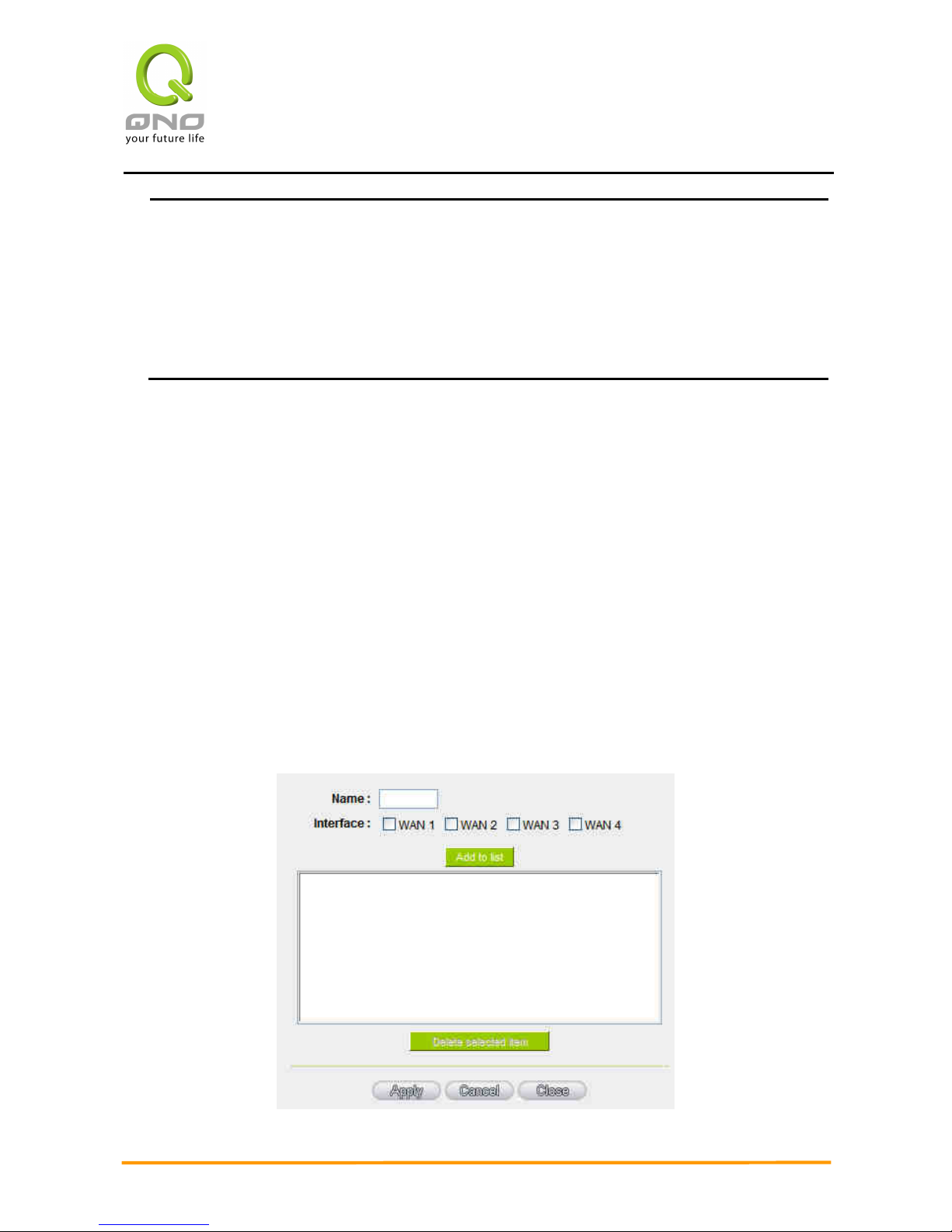
Set WAN Grouping:
If more than one WAN is connected with Netcom, to apply a similar division of traffic
policy to these WANs, a combination for the WANs must be made. Click “Set WAN Grouping”;
an interactive window as shown in the figure below will be displayed.
Page 45
Enterprise Multi-WAN VPN QoS Router
38
Name: To define a name for the WAN grouping in the box, such as
“Education” etc. The name is for recognizing different WAN
groups.
Interface: Check the boxes for the WANs to be added into this
combination.
Add To List: To add a WAN group to the grouping list.
Delete selected
Item:
To remove selected WANs from the WAN grouping.
Apply: Click “Apply” to save the modification.
Close: Click “Cancel” to cancel the modification. This only works
before “Apply” is clicked.
After the configuration is completed, in the China Netcom Policy window users can select
WANs in combination to connect with Netcom.
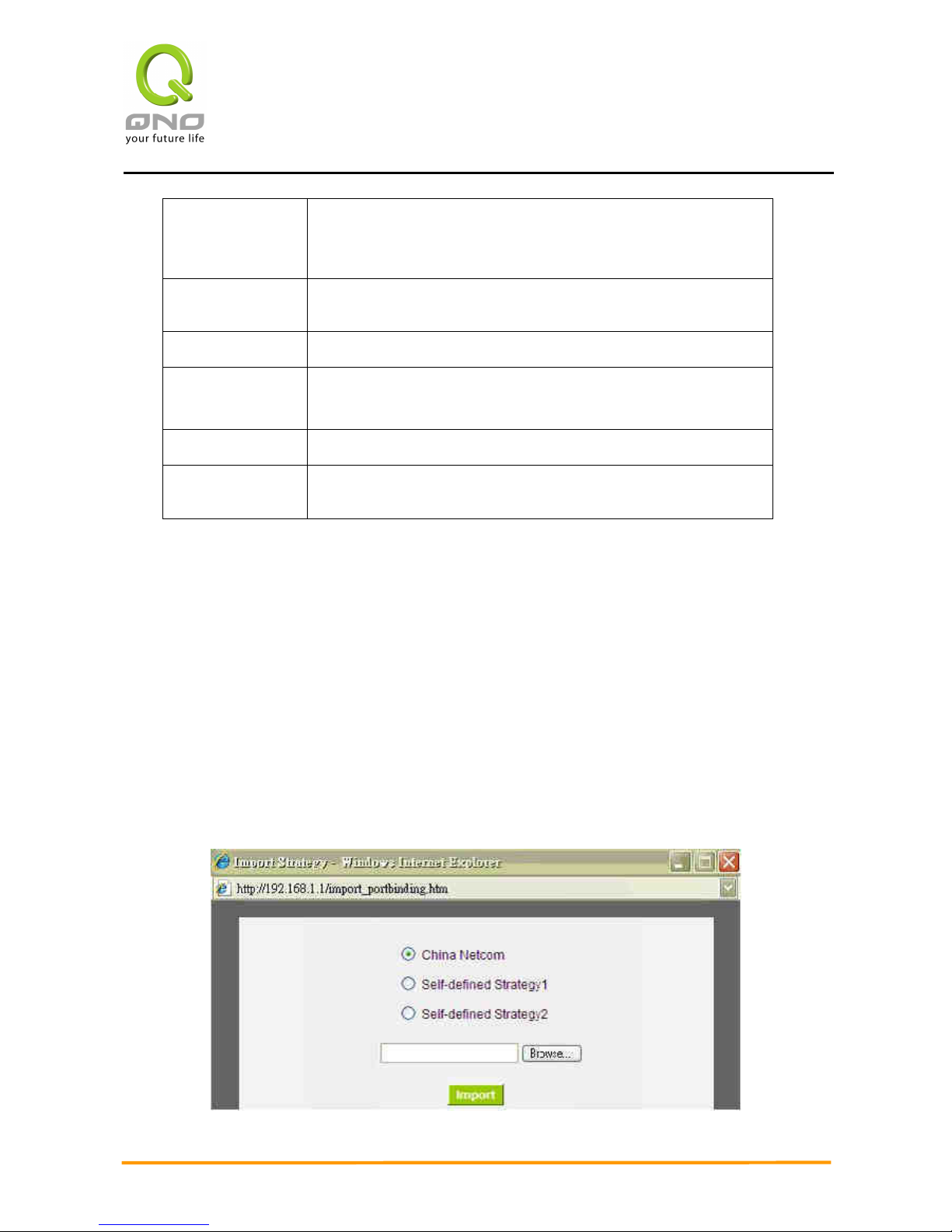
Import Strategy:
A division of traffic policy can be defined by users too. In the “Import Strategy” window, select
the WAN or WAN group (ex. WAN 1) to be assigned and click the “Import IP Range” button; the
dialogue box for document importation will be displayed accordingly. A policy document is an
editable text document. It may contain a destination IP users designated. After the path for
document importation has been selected, click “Import”, and then at the bottom of the
configuration window click “Apply”. The device will then dispatch the traffic to the assigned
destination IP through the WAN (ex. WAN 1) or WAN grouping users designated to the Internet.
Page 46
Enterprise Multi-WAN VPN QoS Router
39
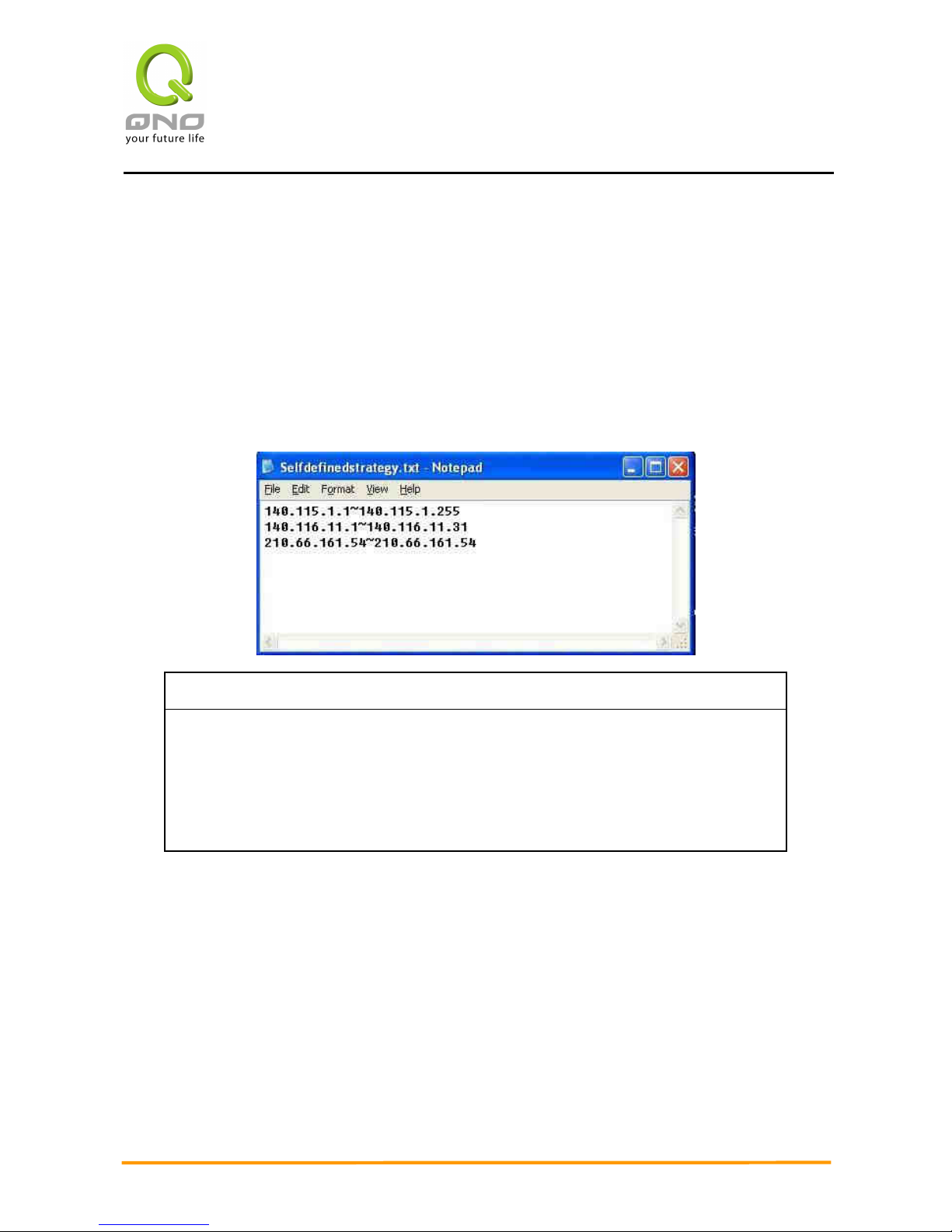
To build a policy document users can use a text-based editor, such as Notepad, which is
included with Windows system. Follow the text format in the figure below to key in the destination
IP addresses users want to assign. For example, if the destination IP address range users want to
designate is 140.115.1.1 ~ 140.115.1.255, key in 140.115.1.1 ~ 140.115.1.255 in Notepad. The
next destination IP address range should be keyed in the next line. Attention! Even if only one
destination IP address is to be assigned, it should follow the same format. For example, if the
destination IP address is 210.66.161.54, it should be keyed in as 210.66.161.54~210.66.161.54.
After the document has been saved (the extension file name is .txt), users can import the IP
range of self-defined strategy.
Note!
China Netcom strategy and self-defined strategy can coexist. However, if a
destination IP is assigned by both China Netcom strategy and self-defined
strategy, China Netcom strategy will take priority. In other words, traffic to that
destination IP will be transmitted through the WAN (or WAN group) under China
Netcom strategy.
6.2.2 Network Detection Service
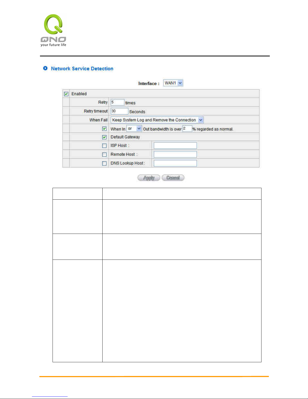
This is a detection system for network external services. If this option is selected, information
such “Retry” or “Retry Timeout” will be displayed. If two WANs are used for external connection,
be sure to activate the NSD system, so as to avoid any unwanted break caused by the device
misjudgment of the overload traffic for the WAN.
Page 47
Enterprise Multi-WAN VPN QoS Router
40
Interface: Select the WAN Port that enables Network Service Detection.
Retry: This selects the retry times for network service detection. The
default is five times. If there is no feedback from the Internet in
the configured “Retry Times", it will be judged as “External
Connection Disconnected”.
Retry Timeout: Delay time for external connection detection latency. The default
is 30 seconds. After the retry timeout, external service detection
will restart.
When Fail: (1) Generate the Error Condition in the System Log: If an
ISP connection failure is detected, an error message will be
recorded in the System Log. This line will not be removed;
therefore, the some of the users on this line will not have
normal connections.
This option is suitable under the condition that one of the WAN
connections has failed; the traffic going through this WAN to
the destination IP cannot shift to another WAN to reach the
destination. For example, if users want the traffic to 10.0.0.1
~ 10.254.254.254 to go only through WAN1, while WAN2 is
not to support these destinations, users should select this
option. When the WAN1 connection is disconnected, packets
Page 48

Enterprise Multi-WAN VPN QoS Router
41
for 10.0.0.1~10.254.254.254 cannot be transmitted through
WAN 2, and there is no need to remove the connection when
WAN 1 is disconnected.
(2) Keep System Log and Remove the Connection: If an ISP
connection failure is detected, no error message will be
recorded in the System Log. The packet transmitted through
this WAN will be shifted to the other WAN automatically, and
be shifted back again when the connection for the original
WAN is repaired and reconnected.
This option is suitable when one of the WAN connections fails
and the traffic going through this WAN to the destination IP
should go through the other WAN to reach the destination. In
this way, when any of the WAN connections is broken, other
WANs can serve as a backup; traffic can be shifted to a WAN
that is still connected.
Detecting Feedback Servers:
Default
Gateway:
The local default communication gateway location, such as the
IP address of an ADSL router, will be input automatically by the
device. Therefore, users just need to check the option if this
function is needed. Attention! Some gateways of an ADSL
network will not affect packet detection. If users have an optical
fiber box, or the IP issued by ISP is a public IP and the gateway
is located at the port of the net café rather than at the IP
provider’s port, do not activate this option.
ISP Host: This is the detected location for the ISP port, such as the DNS IP
address of ISP. When configuring an IP address for this function,
make sure this IP is capable of receiving feedback stably and
speedily. (Please input the DNS IP of the ISP port)
Remote Host: This is the detected location for the remote Network Segment.
This Remote Host IP should better be capable of receiving
feedback stably and speedily. (Please input the DNS IP of the ISP
port).
DNS Lookup
Host:
This is the detect location for DNS. (Only a web address such as
www.hinet.net is acceptable here. Do not input an IP address.)
Page 49
Enterprise Multi-WAN VPN QoS Router
42
In addition, do not input the same web address in this box for
two different WANs.
Note!
In the load balance mode for Assigned Routing, the first WAN port (WAN1) will be saved
for the traffic of the IP addresses or the application service ports that are not assigned to
other WANs (WAN2, WAN3, and WAN4). Therefore, in this mode, we recommend assigning
one of the connections to the first WAN. When other WANs (WAN2, WAN3, or WAN4) are
broken and connection error remove (Remove the Connection) has been selected for the
connection detection system, traffic will be shifted to the first WAN (WAN1). In addition, if
the first WAN (WAN1) is broken, the traffic will be shifted to other WANs in turn. For
example, the traffic will be shifted to WAN2 first; if WAN2 is broken too, the traffic will be
shifted to WAN3, and so on.
6.2.3 Protocol Binding
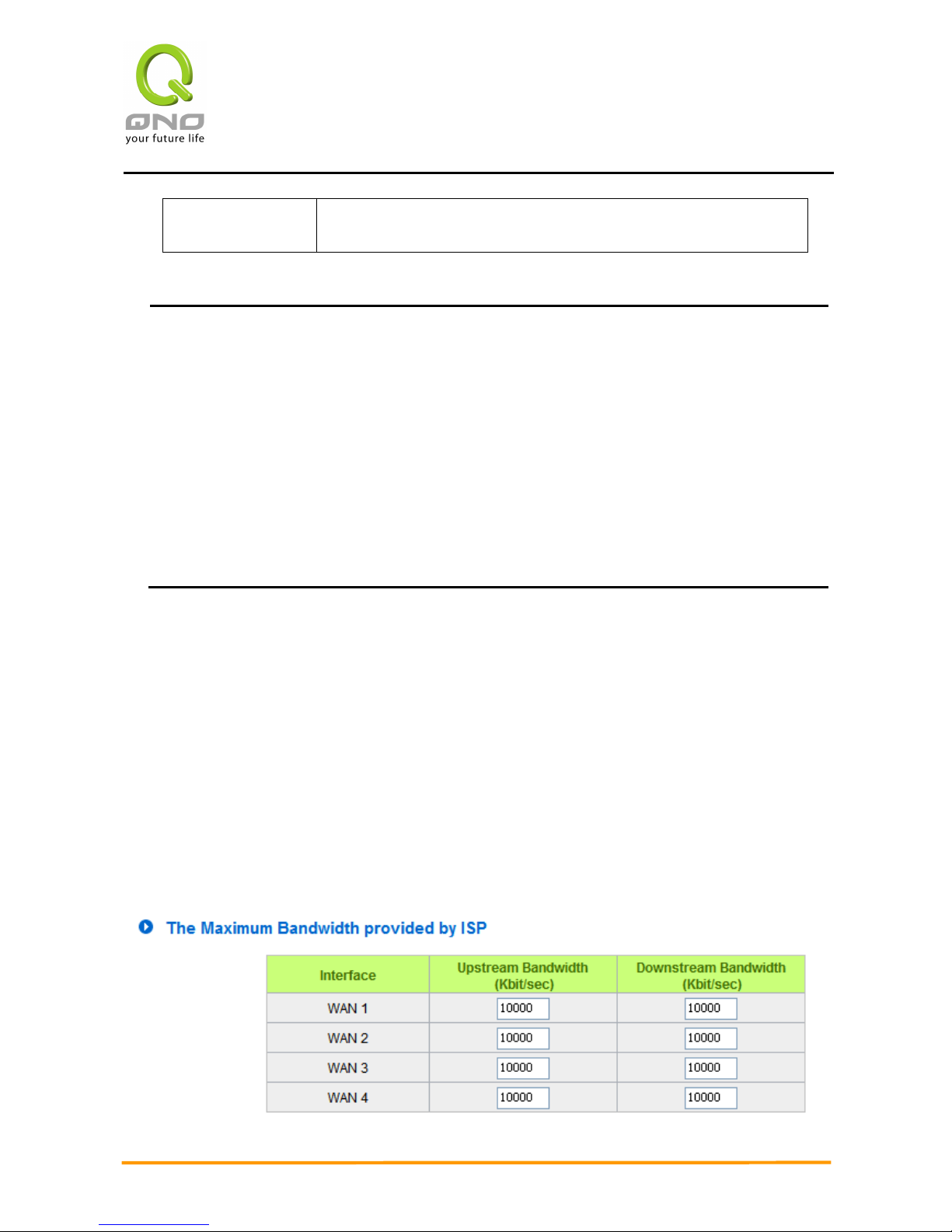
Bandwidth Configuration
When Auto Load Balance mode is selected, the device will select sessions or IP and the WAN
bandwidth will automatically allocate connections to achieve load balancing for external
connections. The network bandwidth is set by what users input for it. For example, if the upload
bandwidth of both WANs is 512Kbit/sec, the automatic load ratio will be 1:1; if one of the upload
bandwidths is 1024Kbit/sec, while the other is 512Kbit/sec, the automatic load ratio will be 2:1.
Therefore, to ensure that the device can balance the actual network load, please input real upload
and download bandwidths. The section refers to QoS configuration. Therefore, it should be set in
QoS page. Please refer to 8.1 QoS bandwidth configuration.
Page 50
Enterprise Multi-WAN VPN QoS Router
43
Protocol Binding
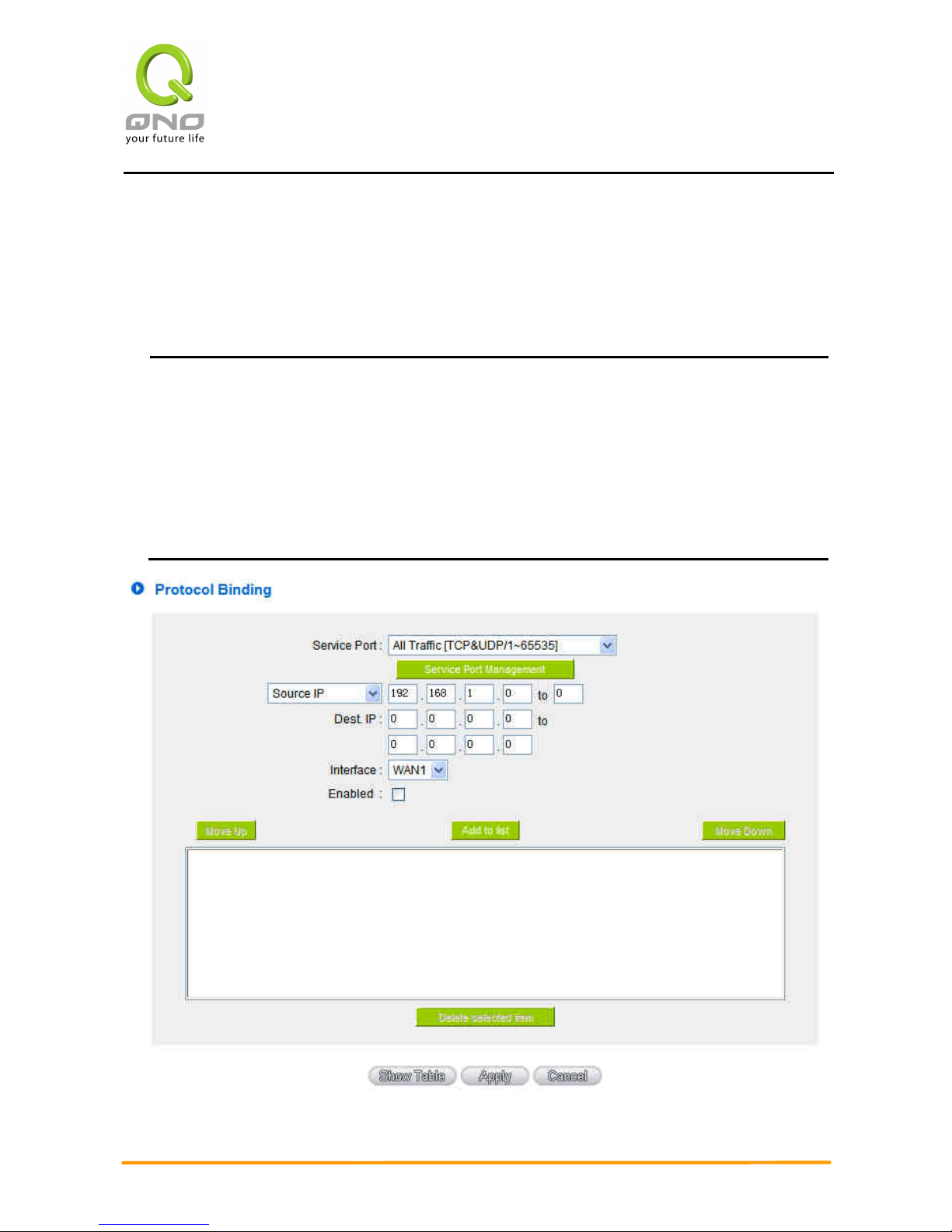
Users can define specific IP addresses or specific application service ports to go through a
user-assigned WAN for external connections. For any other unassigned IP addresses and services,
WAN load balancing will still be carried out.
Note!
In the load balance mode of Assigned Routing, the first WAN (WAN1) cannot be
assigned. It is to be saved for the IP addresses and the application Service Ports that are not
assigned to other WANs (WAN2, WAN3, and WAN4) for external connections. In other
words, the first WAN (WAN1) cannot be configured with the Protocol Binding rule. This is to
avoid a condition where all WANs are assigned to specific Intranet IP or Service Ports and
destination IP, no more WAN ports will be available for other IP addresses and Service Ports.
Page 51

Enterprise Multi-WAN VPN QoS Router
44
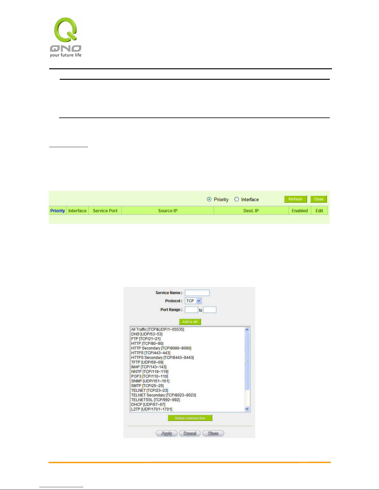
Service: This is to select the Binding Service Port to be activated. The
default (such as ALL-TCP&UDP 0~65535, WWW 80~80, FTP 21 to
21, etc.) can be selected from the pull-down option list. The default
Service is All 0~65535.
Option List for Service Management: Click the button to enter the
Service Port configuration page to add or remove default Service
Ports on the option list.
Source IP: Users can assign packets of specific Intranet virtual IP to go
through a specific WAN port for external connection. In the boxes
here, input the Intranet virtual IP address range; for example, if
192.168.1.100~150 is input, the binding range will be 100~150. If
only specific Service Ports need to be designated, while specific IP
designation is not necessary, input “0” in the IP boxes.
Destination
IP:
In the boxes, input an external static IP address. For example, if
connections to destination IP address 210.11.1.1 are to be
restricted to WAN1, the external static IP address 210.1.1.1 ~
210.1.1.1 should be input. If a range of destinations is to be
assigned, input the range such as 210.11.1.1 ~ 210.11.255.254.
This means the Class B Network Segment of 210.11.x.x will be
restricted to a specific WAN. If only specific Service Ports need to
be designated, while a specific IP destination assignment is not
required, input “0” into the IP boxes.
Interface: Select the WAN for which users want to set up the binding rule.
Enable: To activate the rule.
Add To List: To add this rule to the list.
Delete
selected
application:
To remove the rules selected from the Service List.
Moving Up &
Down:
The priority for rule execution depends on the rule order in the list.
A rule located at the top will be executed prior to those located
below it. Users can arrange the order according to their priorities.
Page 52
Enterprise Multi-WAN VPN QoS Router
45
Note!
The rules configured in Protocol Binding will be executed by the device according to
their priorities too. The higher up on the list, the higher the priority of execution.
Show Table:
Click the “Show Table” button. A dialogue box as shown in the following figure will be
displayed. Users can choose to sort the list by priorities or by interface. Click “Refresh” and the
page will be refreshed; click “Close” and the dialogue box will be closed.
Add or Remove Service Port
If the Service Port users want to activate is not in the list, users can add or remove
service ports from “Service Port Management” to arrange the list, as described in the
following:
Page 53

Enterprise Multi-WAN VPN QoS Router
46
Service Name: In this box, input the name of the Service Port which
users want to activate, such as BT, etc.
Protocol: This option list is for selecting a packet format, such as
TCP or UDP for the Service Ports users want to activate.
Port range: In the boxes, input the range of Service Ports users
want to add.
Add To List: Click the button to add the configuration into the
Services List. Users can add up to 100 services into the
list.
Delete selected
service:
To remove the selected activated Services.
Apply: Click the “Apply” button to save the modification.
Cancel: Click the “Cancel” button to cancel the modification.
This only works before “Apply” is clicked.
Close: To quit this configuration window.
Auto Load Balancing mode when enabled:
The collocation of the Auto Load Balance Mode and the Auto Load Mode will enable more
flexible use of bandwidth. Users can assign specific Intranet IP addresses to specific
destination application service ports or assign specific destination IP addresses to a WAN
users choose for external connections.
Example 1:How do I set up Auto Load Balance Mode to assign the Intranet IP 192.168.1.100 to
WAN2 for the Internet?
Page 54
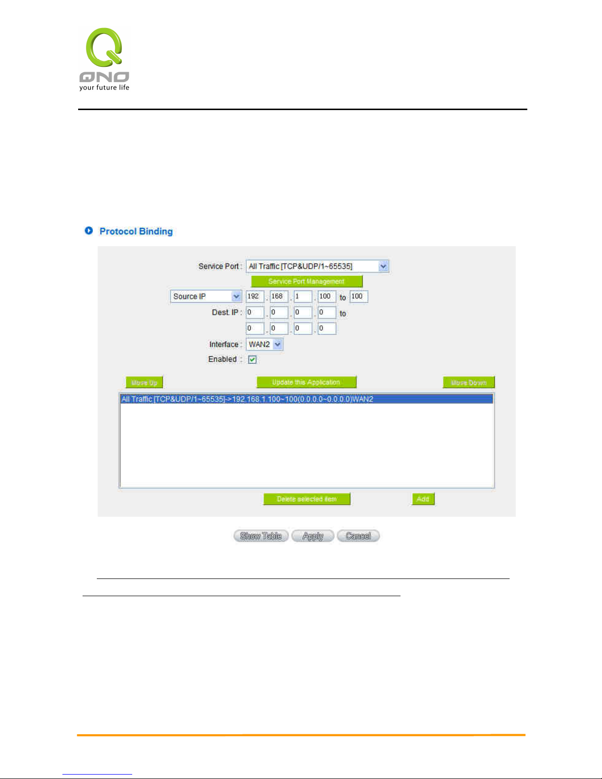
Enterprise Multi-WAN VPN QoS Router
47
As in the figure below, select “All Traffic” from the pull-down option list “Service”, and
then in the boxes of “Source IP” input the source IP address “192.168.1.100” to “100”.
Retain the original numbers “0.0.0.0” in the boxes of “Destination IP” (which means to
include all Internet IP addresses). Select WAN2 from the pull-down option list “Interface”,
and then click “Enable”. Finally, click “Add New” and the rule will be added to the mode.
Example 2:How do I set up Auto Load Balance Mode to keep Intranet IP 192.168.1.150 ~
200 from going through WAN2 when the destination port is Port 80?
As in the figure below, select “HTTP [TCP/80~80]” from the pull-down option list
“Service”, and then in the boxes for “Source IP” input “192.168.1.150” to “200”. Retain the
original numbers “0.0.0.0” in the boxes of “Destination IP” (which means to include all
Internet IP addresses). Select WAN2 from the pull-down option list “Interface”, and then
click “Enable”. Finally, click “Add New” and the rule will be added to the mode.
Page 55
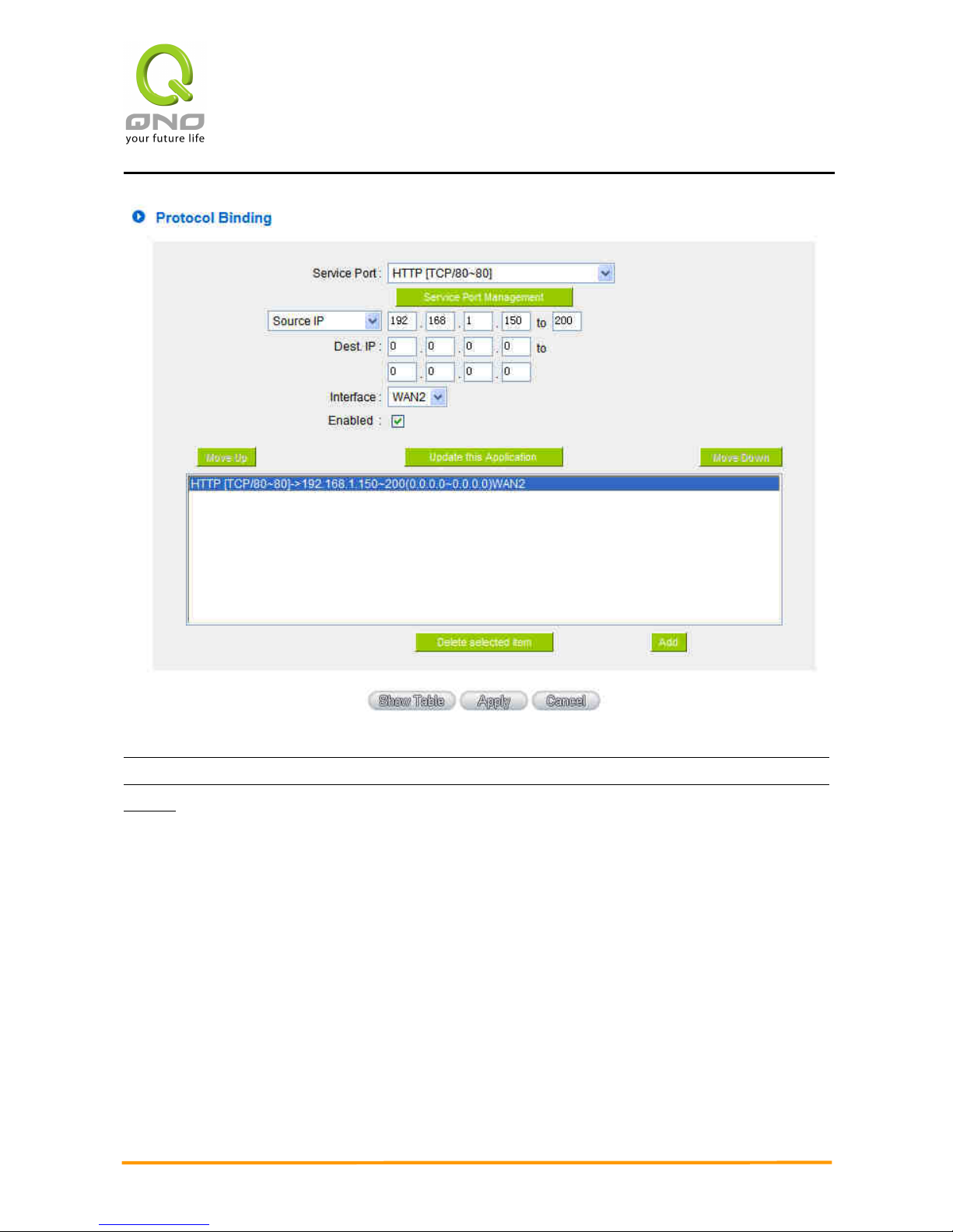
Enterprise Multi-WAN VPN QoS Router
48
Example 3:How do I set up Auto Load Balance Mode to keep all Intranet IP addresses from going
through WAN2 when the destination port is Port 80 and keep all other services from going through
WAN1?
As in the figure below, there are two rules to be configured. The first rule: select “HTTP
[TCP/80~80]” from the pull-down option list “Service”, and then in the boxes of Source IP
input “192.168.1.0” to “0” (which means to include all Intranet IP addresses). Retain the
original numbers “0.0.0.0” in the boxes of “Destination IP” (Which means to include all
Internet IP addresses). Select WAN2 from the pull-down option list “Interface”, and then
click “Enable”. Finally, click “Add New” and the rule will be added to the mode. The device
will transmit packets to Port 80 through WAN2. However, with only the above rule, packets
that do not go to Port 80 may be transmitted through WAN2; therefore, a second rule is
necessary. The second rule: Select “All Ports [TCP&UDP/1~65535]” from the pull-down
option list “Service”, and then input “192.168.1.2 ~ 254” in the boxes of “Source IP”. Retain
the original numbers “0.0.0.0” in the boxes of “Destination IP” (which means to include all
Page 56
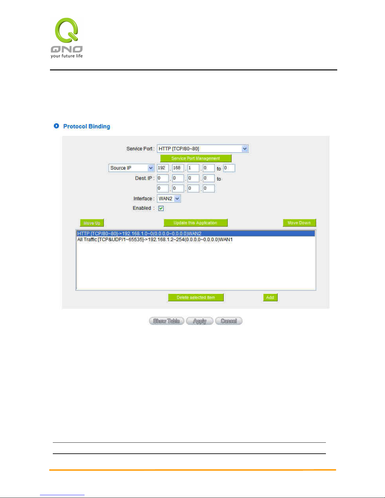
Enterprise Multi-WAN VPN QoS Router
49
Internet IP addresses). Select WAN1 from the pull-down option list “Interface”, and then
click “Enable”. Finally, click “Add New” and the rule will be added to the mode. The device
will transmit packets that are not going to Port 80 to the Internet through WAN1.
Configuring “Assigned Routing Mode” for load Balance:
IP Group: This function allows users to assign packets from specific Intranet IP
addresses or to specific destination Service Ports and to specific destination IP addresses
through an assigned WAN to the Internet. After being assigned, the specific WAN will only
support those assigned Intranet IP addresses, destination Service Ports, or destination IP
addresses. Those which are not configured will go through other WANs for external
connection. Only when this mode is collocated with “Assigned Routing” can it bring the
function into full play.
Example 1:How do I set up the Assigned Routing Mode to keep all Intranet IP addresses from
going through WAN2 when the destination is Port 80, and keep all other services from going
Page 57
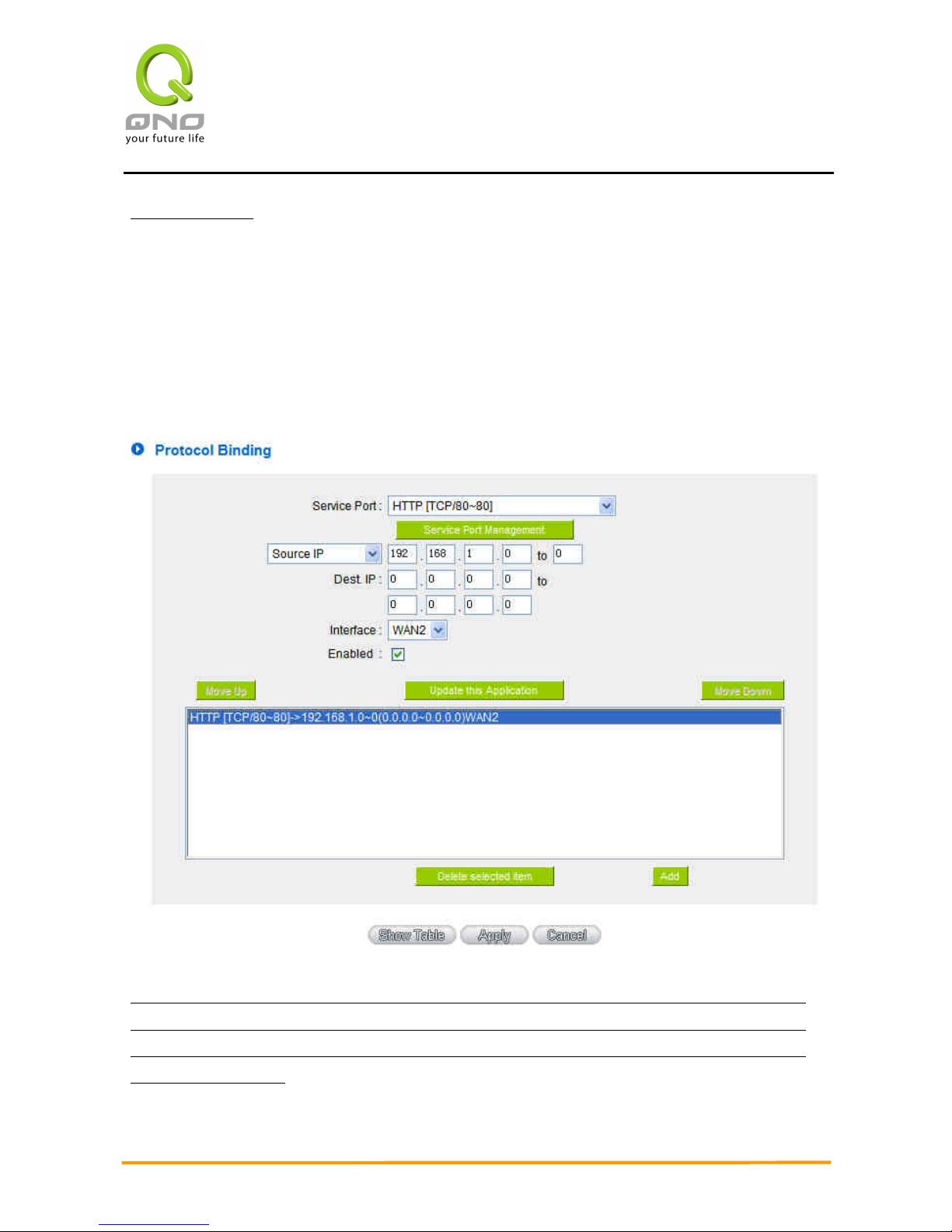
Enterprise Multi-WAN VPN QoS Router
50
through WAN1?
As in the figure below, select “HTTP[TCP/80~80]” from the pull-down option list
“Service”, and then in the boxes of “Source IP” input “192.168.1.0 ~ 0” (which means to
include all Intranet IP addresses). Retain the original numbers “0.0.0.0” in the boxes of
“Destination IP” (Which means to include all Internet IP addresses). Select WAN2 from the
pull-down option list “Interface”, and then click “Enable”. Finally, click “Add New” and the
rule will be added to the mode. After the rule is set up, only packets that go to Port 80 will
be transmitted through WAN2, while other traffics will be transmitted through WAN1.
Example 2:How do I configure Protocol Binding to keep traffic from all Intranet IP addresses
from going through WAN2 when the destinations are IP 211.1.1.1 ~ 211.254.254.254 as well
as the whole Class A group of 60.1.1.1 ~ 60.254.254.254, while traffic to other destinations
goes through WAN1?
As in the following figure, there are two rules to be configured. The first rule: Select “All
Page 58
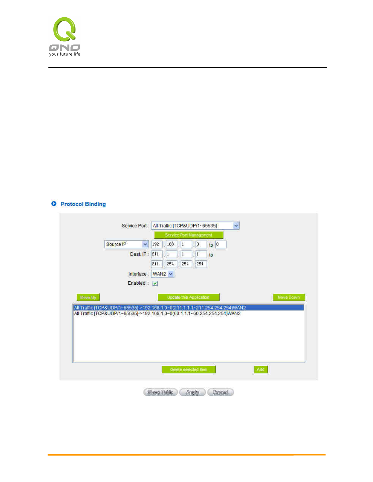
Enterprise Multi-WAN VPN QoS Router
51
Port [TCP&UDP/1~65535]” from the pull-down option list “Service”, and then in the boxes
of “Source IP” input “192.168.1.0 ~ 0” (which means to include all Intranet IP addresses).
In the boxes for “Destination IP” input “211.1.1.1 ~ 211.254.254.254”. Select WAN2 from
the pull-down option list “Interface”, and then click “Enable”. Finally, click “Add New” and
the rule will be added to the mode. The second rule: Select “All Port [TCP&UDP/1~65535]”
from the pull-down option list “Service”, and then in the boxes of “Source IP” input
“192.168.1.0 ~ 0” (which means to include all Intranet IP addresses). In the boxes of
“Destination IP” input “211.1.1.1 ~ 60,254,254,254”. Select WAN2 from the pull-down
option list “Interface”, and then click “Enable”. Finally, click “Add New”, and the rule will be
added to the mode. After the rule has been set up, all traffic that is not going to the
assigned destinations will only be transmitted through WAN1.
Page 59
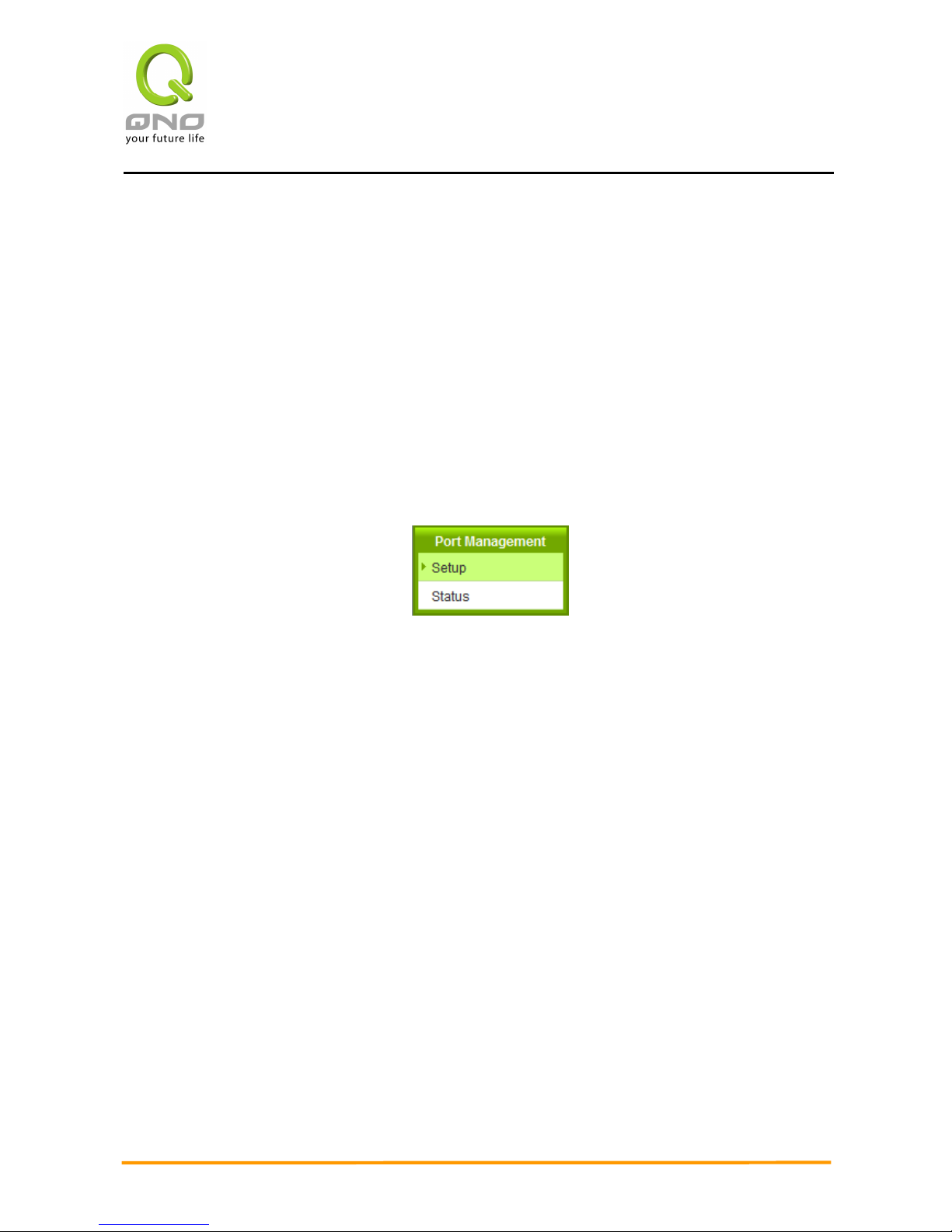
Enterprise Multi-WAN VPN QoS Router
52
VII. Port Management
This chapter introduces how to configure ports and understand how to configure intranet IP
addresses.
7.1 Setup
Through the device, users can easily manage the setup for WAN ports, LAN ports and the
DMZ port by choosing the number of ports, speed, priority, duplex and enable/disable the
auto-negotiation feature for connection setting of each port.
Page 60
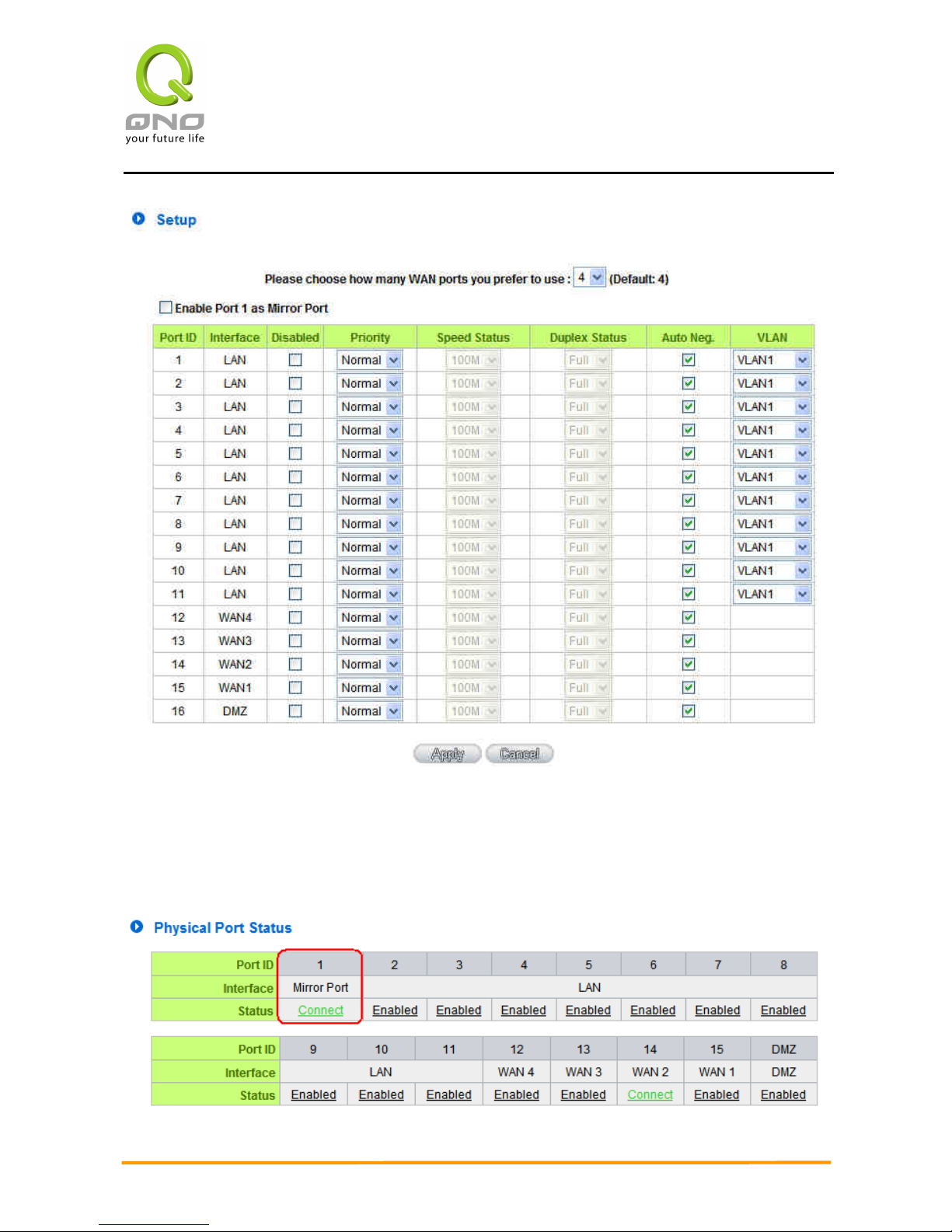
Enterprise Multi-WAN VPN QoS Router
53
Mirror Port:Users can configure LAN 1 as mirror port by choosing “Enable Port 1 as Mirror
Port”. All the traffic from LAN to WAN will be copied to mirror port. Administrator can control or
filter the traffic through mirror port. Once this function is enabled, LAN 1 will be shown as Mirror
Port in Physical Port Status, Home page.
Page 61

Enterprise Multi-WAN VPN QoS Router
54
Disabled:
This feature allows users turn on/off the Ethernet port. If selected,
the Ethernet port will be shut down immediately and no connection
can be made. The default value is "on".
Priority:
This feature allows users to set the high/low priority of the packet
delivery for the Ethernet port. If it is set as High, the port has the
first priority to deliver the packet. The default value is “Normal”.
Speed:
This feature allows users to select the network hardware
connection speed for the Ethernet port. The options are 10Mbps
and 100Mbps.
Duplex Status:
This feature allows users to select the network hardware
connection speed working mode for the Ethernet. The options are
full duplex and half duplex.
Auto Neg.:
The Auto-Negotiation mode can enable each port to automatically
adjust and gather the connection speed and duplex mode.
Therefore, if Enabled Auto-Neg. selected, the ports setup will be
done without any manual setting by administrators.
VLAN:
This feature allows administrators to set the LAN port to be one or
more disconnected network sessions. All of them will be able to log
on to the Internet through the device.
Members in the same network session (within the same VLAN) can
see and communicate with each other. Members in different VLAN
will not know the existence of other members.
VLAN All:
Set VLAN All port to be the public area of VLAN so that it can be
connected to other VLAN networks. A server should be constructed
for the intranet so that all VLAN group can visit this server. Set one
of the network ports as VLAN All. Connect the server to VLAN All so
that computers of different VLAN groups can be connected to this
server. Moreover, the port where the administrator locates must be
set as VLAN All so that it can be connected to the entire network to
facilitate network management.
Page 62
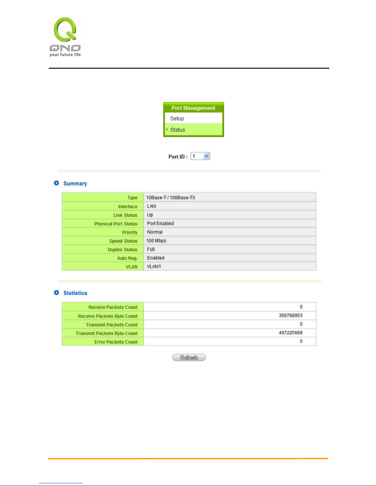
Enterprise Multi-WAN VPN QoS Router
55
7.2 Port Status
Summary:
There are Network Connection Type, Interface, Link Status (Up/Down), Port Activity (Port
Enabled), Priority Setting (High or Normal), Speed Status (10Mbps or 100Mbps), Duplex Status
(half duplex or full duplex), Auto Neg. (Enabled/Disabled), and VLAN.
Page 63

Enterprise Multi-WAN VPN QoS Router
56
Statistics:
The packet data of this specific port will be displayed. Data include receive/ transmit
packet count, receive/ transmit packet Byte count and error packet count. Users may press
the refresh button to update all real-time messages.
Page 64
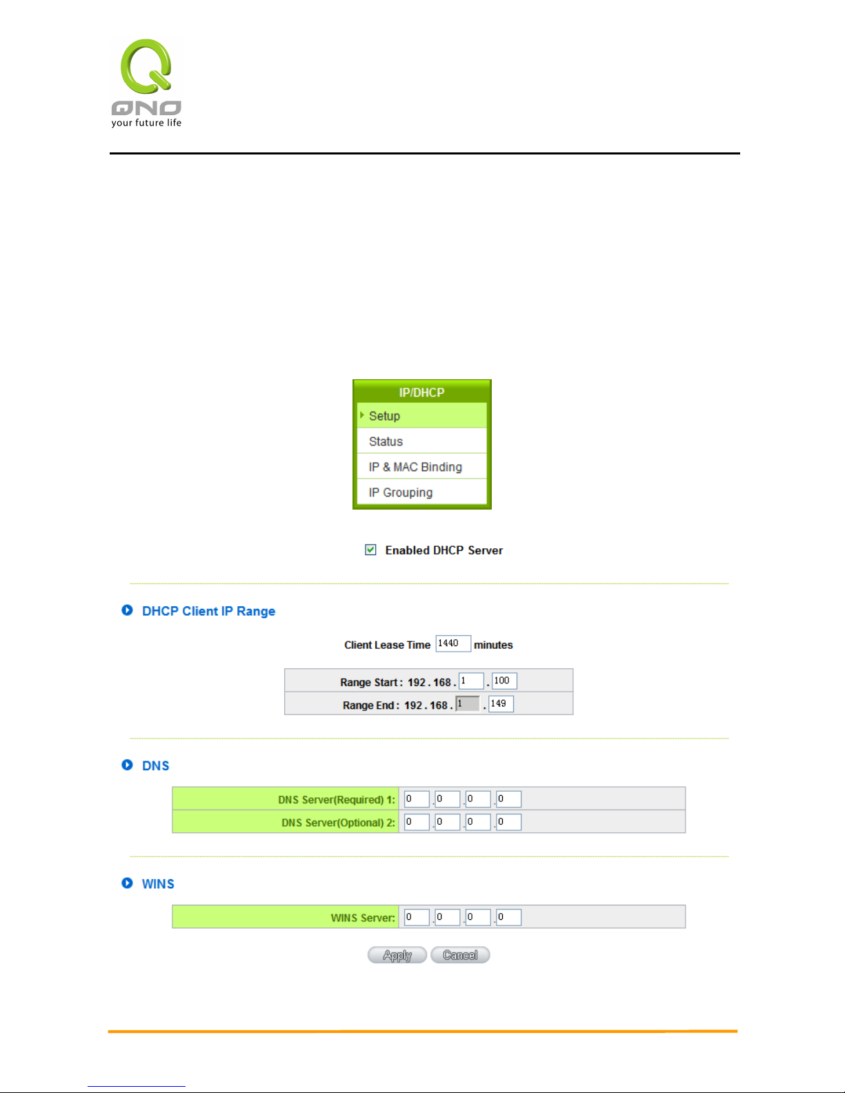
Enterprise Multi-WAN VPN QoS Router
57
7.3 IP/ DHCP
With an embedded DHCP server, it supports automatic IP assignation for LAN
computers. (This function is similar to the DHCP service in NT servers.) It benefits users by
freeing them from the inconvenience of recording and configuring IP addresses for each PC
respectively. When a computer is turned on, it will acquire an IP address from the device
automatically. This function is to make management easier.
Page 65

Enterprise Multi-WAN VPN QoS Router
58
Dynamic IP:
Client lease Time:
Check the option to activate the DHCP server automatic IP lease
function. If the function is activated, all PCs will be able to acquire
IP automatically. Otherwise, users should configure static virtual
IP for each PC individually.
Range Start:
This is to set up a lease time for the IP address which is acquired
by a PC. The default is 1440 minutes (a day). Users can change it
according to their needs. The time unit is minute.
Range End:
This is an initial IP automatically leased by DHCP. It means DHCP
will start the lease from this IP. The default initial IP is
192.168.1.100.
DNS (Domain Name Service):
This is for checking the DNS from which an IP address has been leased to a PC port.
Input the IP address of this server directly.
DNS (Required) 1:
Input the IP address of the DNS server.
DNS (Optional) 2:
Input the IP address of the DNS server.
WINS:
If there is a WIN server in the network, users can input the IP address of that server
directly.
WINS Server:
Input the IP address of WINS.
Apply:
Click “Apply” to save the network configuration modification.
Cancel:
Click “Cancel" to leave without making any changes.
Page 66
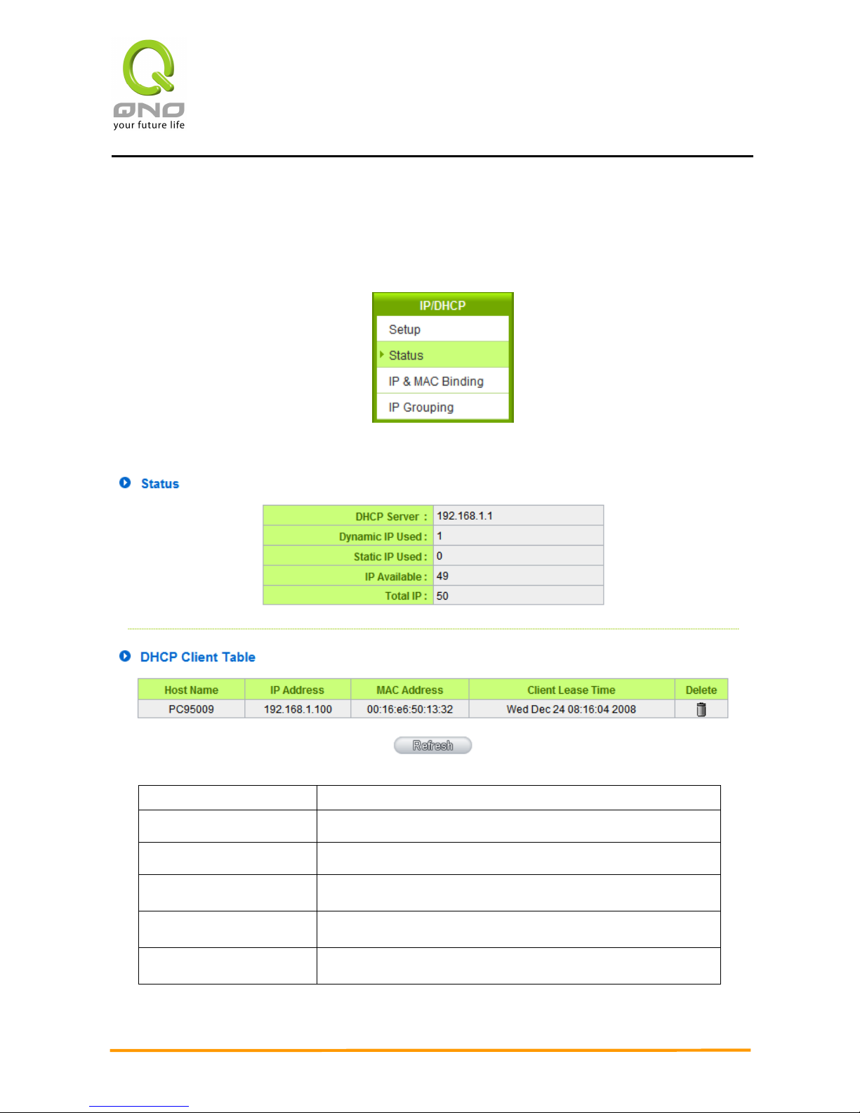
Enterprise Multi-WAN VPN QoS Router
59
7.4 DHCP Status
This is an indication list of the current status and setup record of the DHCP server. The
indications are for the administrator’s reference when a network modification is needed.
DHCP Server:
This is the current DHCP IP.
Dynamic IP Used:
The amount of dynamic IP leased by DHCP.
Static IP Used:
The amount of static IP assigned by DHCP.
IP Available:
The amount of IP still available in the DHCP server.
Total IP:
The total IP which the DHCP server is configured to lease.
Host Name:
The name of the current computer.
Page 67

Enterprise Multi-WAN VPN QoS Router
60
IP Address:
The IP address acquired by the current computer.
MAC Address:
The actual MAC network location of the current computer.
Client Lease Time:
The lease time of the IP released by DHCP.
Delete:
Remove a record of an IP lease.
Page 68
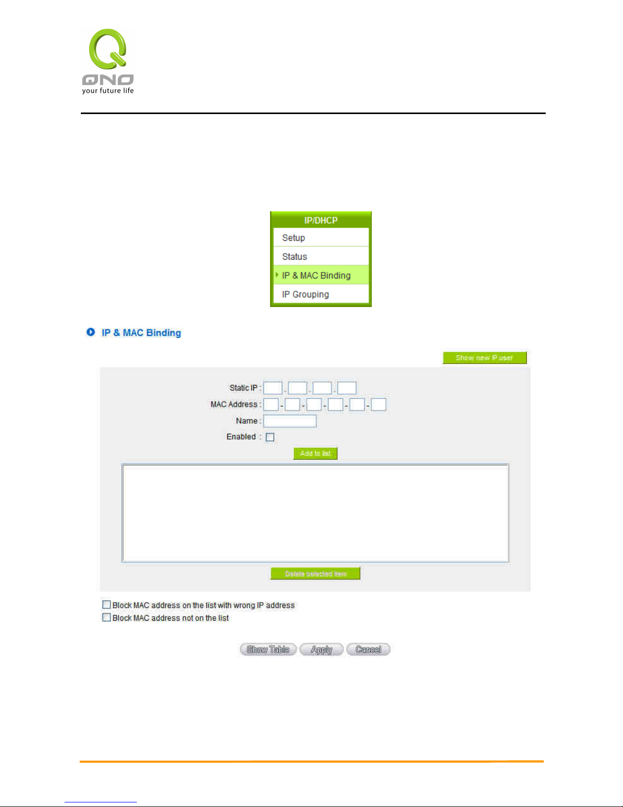
Enterprise Multi-WAN VPN QoS Router
61
7.5 IP & MAC Binding
Administrators can apply IP & MAC Binding function to make sure that users can not add extra
PCs for Internet access or change private IP addresses.
There are two methods for setting up this function:
Page 69
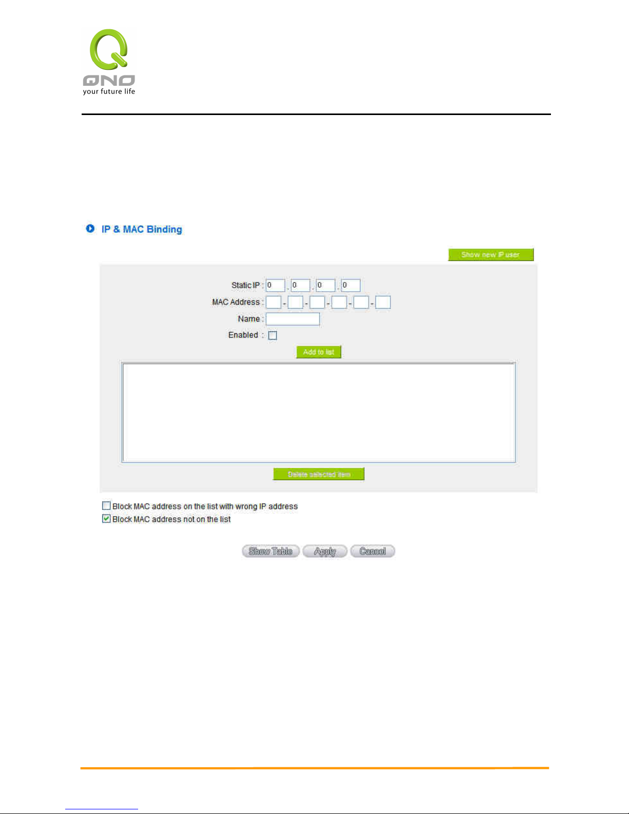
Enterprise Multi-WAN VPN QoS Router
62
Block MAC address not on the list
This method only allows MAC addresses on the list to receive IP addresses from DHCP and have
Internet access. When this method is applied, please fill out Static IP with 0.0.0.0, as the figure
below:
IP & MAC Binding
Page 70
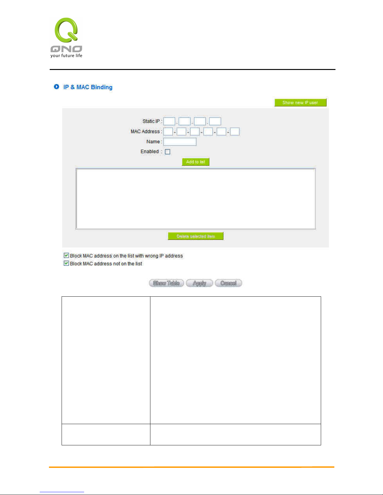
Enterprise Multi-WAN VPN QoS Router
63
Static IP:
There are two ways to input static IP:
1. If users want to set up a MAC address to acquire IP
from DHCP, but the IP need not be a specific
assigned IP, input 0.0.0.0 in the boxes. The boxes
cannot be left empty.
2. If users want DHCP to assign a static IP for a PC
every single time, users should input the IP
address users want to assign to this computer in
the boxes. The server or PC which is to be bound
will then acquire a static virtual IP whenever it
restarts.
MAC Address:
Input the static real MAC (the address on the network
card) for the server or PC which is to be bound.
Page 71
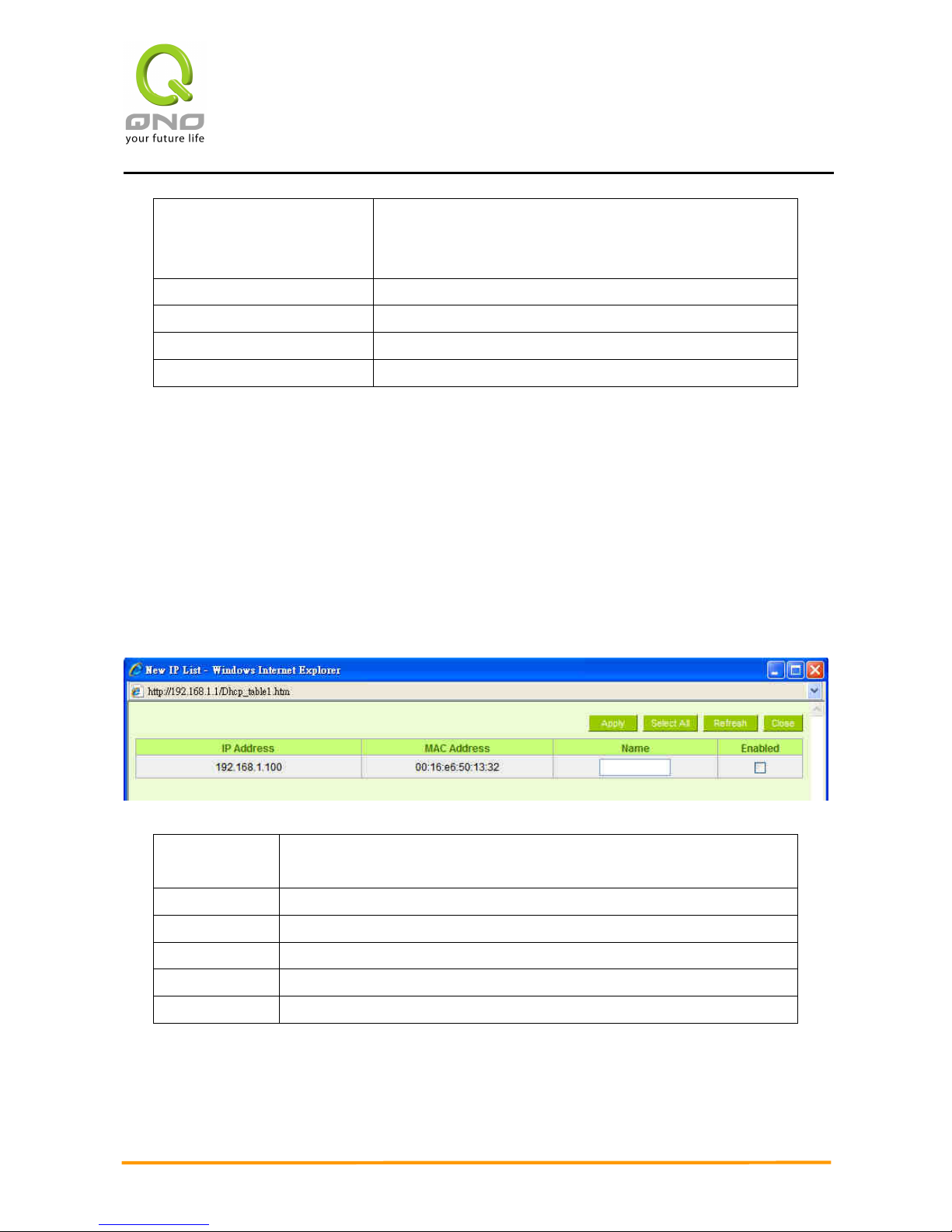
Enterprise Multi-WAN VPN QoS Router
64
Name:
For distinguishing clients, input the name or address of
the client that is to be bound. The maximum acceptable
characters are 12.
Enabled:
Activate this configuration.
Add to list:
Add the configuration or modification to the list.
Delete selected item:
Remove the selected binding from the list.
Add:
Add new binding.
Block MAC address on the list with wrong IP address: When this option is activated, MAC
addresses which are not included in the list will not be able to connect with the Internet.
Show New IP user:
This function can reduce administrator’s effort on checking MAC addresses one by one for the
binding. Furthermore, it is easy to make mistakes to fill out MAC addresses on the list
manually. By checking this list, administrator can see all MAC addresses which have traffic and
are not bound yet. Also, if administrators find that one specific bound MAC address is shown on
the list, it means that the user changes the private IP address.
Name:
Input the name or address of the client that is to be bound. The
maximum acceptable characters are 12.
Enabled:
Choose the item to be bound.
Apply:
Activate the configuration.
Select All:
Choose all items on the list for binding.
Refresh:
Refresh the list.
Close:
Close the list.
Page 72
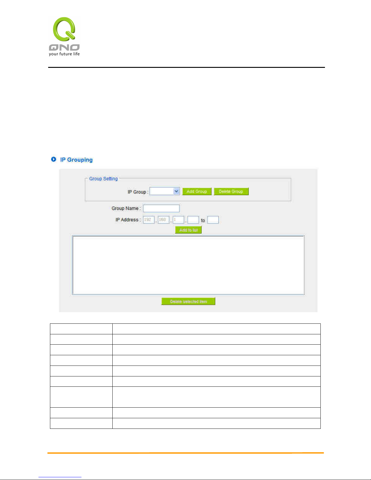
Enterprise Multi-WAN VPN QoS Router
65
7.6 IP Grouping
The function enables users to make the same configuration for a range of continuous IP
addresses in the network. For example, if an IP range (192.168.1.100~192.168.1.110) has been
assigned to a department of a company, we can bind all the IP addresses together and make an
accessing rule configuration for them all at the same time, instead of configuring each IP
respectively, which takes more time and is more prone to error.
IP Group:
Select a group to which the modification is to be made.
Add Group:
Click Add Group to crate a new IP group.
Delete Group:
Delete the chosen IP group.
Group Name:
Input or change the name for the group.
IP Address:
Input the assigned IP range.
Add to list:
Add the configuration or modification to the list.
Delete selected
item:
Remove the selected binding from the list.
Apply:
Click “Apply” to save the network configuration modification
Cancel:
Click “Cancel" to leave without making any changes.
Page 73
Enterprise Multi-WAN VPN QoS Router
66
VIII. QoS (Quality of Service)
QoS is an abbreviation for Quality of Service. The main function is to restrict bandwidth
usage for some services and IP addresses to save bandwidth or provide priority to specific
applications or services, and also to enable other users to share bandwidth, as well as to
ensure stable and reliable network transmission. To maximize the bandwidth efficiency,
network administrators should take account of the practical requirements of a company, a
community, a building, or a café, etc., and modify bandwidth management according to the
network environment, application processes or services.
Page 74
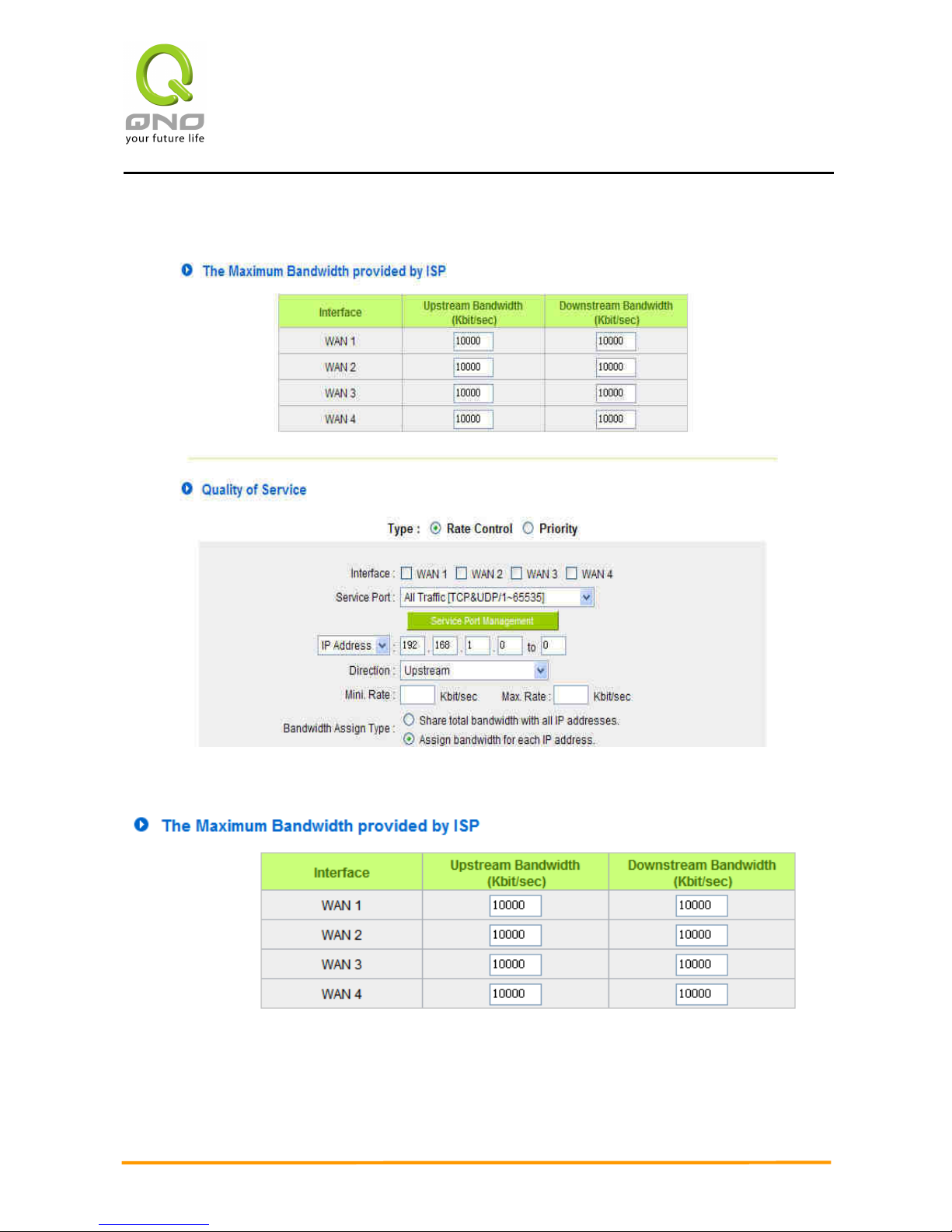
Enterprise Multi-WAN VPN QoS Router
67
8.1 Bandwidth Management
8.1.1 The Maximum Bandwidth provided by ISP
In the boxes for WAN1 and WAN2 bandwidth, input the upstream and downstream
bandwidth which users applied for from bandwidth supplier. The bandwidth QoS will make
calculations according to the data users input. In other words, it will guarantee a minimum
Page 75

Enterprise Multi-WAN VPN QoS Router
68
rate of upstream and downstream for each IP and Service Port based on the total actual
bandwidth of WAN1 and WAN2. For example, if the upstream bandwidths of both WAN1 and
WAN2 are 512Kbit/Sec, the total upstream bandwidth will be: WAN1 + WAN2 =
1024Kbit/Sec. Therefore, if there are 50 IP addresses in the Intranet, the minimum
guaranteed upstream bandwidth for each IP would be 1024Kbit/50=20Kbit/Sec. Thus,
20Kbit/Sec can be input for “Mini. Rate” Downstream bandwidth can be calculated in the
same way.
Attention!
The unit of calculation in this example is Kbit. Some software indicates the
downstream/upstream speed with the unit KB. 1KB = 8Kbit.
8.1.2 QoS
To satisfy the bandwidth requirements of certain users, the device enables users to set up
QoS: Rate Control and Priority Control. Users can select only one of the above QoS choices.
Rate Control:
The network administrator can set up bandwidth or usage limitations for each IP or IP range
according to the actual bandwidth. The network administrator can also set bandwidth
control for certain Service Ports. A guarantee bandwidth control for external connections
can also be configured if there is an internal server.
Page 76
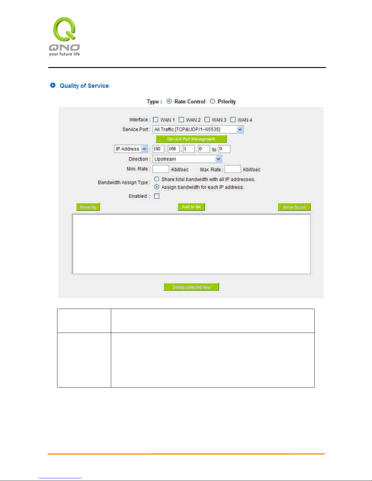
Enterprise Multi-WAN VPN QoS Router
69
Interface:
Select on which WAN the QoS rule should be executed. It can be a
single selection or multiple selections.
Service Port:
Select what bandwidth control is to be configured in the QoS rule. If
the bandwidth for all services of each IP is to be controlled, select “All
(TCP&UDP) 1~65535”. If only FTP uploads or downloads need to be
controlled, select “FTP Port 21~21”. Refer to the Default Service Port
Number List.
Page 77

Enterprise Multi-WAN VPN QoS Router
70
IP Address:
This is to select which user is to be controlled. If only a single IP is to
be restricted, input this IP address, such as “192.168.1.100 to 100”.
The rule will control only the IP 192.168.1.100. If an IP range is to be
controlled, input the range, such as “192.168.1.100 ~ 150”. The rule
will control IP addresses from 192.168.1.100 to 150. If all Intranet
users that connect with the device are to be controlled, input “0” in
the boxes of IP address. This means all Intranet IP addresses will be
restricted. QoS can also control the range of Class B.
Direction:
Upstream: Means the upload bandwidth for Intranet IP.
Downstream: Means the download bandwidth for Intranet IP.
Server in LAN, Upstream: If a Server for external connection has
been built in the device, this option is to control the bandwidth for the
traffic coming from outside to this Server.
Server in LAN, Downstream: If there are web sites built in the
Intranet, this option is to control the upload bandwidth for the
connections from outside to this Server. For example, game servers
have been built in many Internet cafés. This rule can be used to
control the bandwidth for connections from outside to the game
server of a café to update data. In this way, game players inside the
café will not be affected.
Min. & Max.
Rate:
(Kbit/Sec)
The minimum bandwidth: The rule is to guarantee minimum
available bandwidth.
The maximum bandwidth: This rule is to restrict maximum available
bandwidth. The maximum bandwidth will not exceed the limit set up
under this rule.
Attention! The unit of calculation used in this rule is Kbit. Some
software indicates download/upload speed by the unit KB. 1KB =
8Kbit.
Page 78

Enterprise Multi-WAN VPN QoS Router
71
Bandwidth
Assign Type:
Sharing total bandwidth with all IP addresses: If this option is
selected, all IP addresses or Service Ports will share the bandwidth
range (from minimum to maximum bandwidth).
Assign bandwidth for each IP address: If this option is selected, every
IP or Service Port in this range can have this bandwidth (minimum to
maximum). For example, If the rule is set for the IP of each PC, the IP
of each PC will have the same bandwidth.
Attention: If “Share-Bandwidth” is selected, be aware of the actual
usage conditions and avoid an improper configuration that might
cause a malfunction of the network when the bandwidth is too small.
For example, if users do not want an FTP to occupy too much
bandwidth, users can select the “Share-Bandwidth Mode”, so that no
matter how much users use FTPs to download information, the total
occupied bandwidth is fixed.
Enable:
Activate the rule.
Add to list:
Add this rule to the list.
Move up & Move
down:
QoS rules will be executed from the bottom of the list to the top of the
list. In other words, the lower down the list, the higher the priority of
execution. Users can arrange the sequence according to their
priorities. Usually the service ports which need to be restricted, such
as BT, e-mule, etc., will be moved to the bottom of the list. The rules
for certain IP addresses would then be moved upward.
Delete selected
items:
Remove the rules selected from the Service List.
Show Table:
Display all the Rate Control Rules users made for the bandwidth.
Click “Edit” to modify.
Apply:
Click “Apply” to save the configuration
Cancel:
Click “Cancel" to leave without making any change.
Show Table:
Page 79
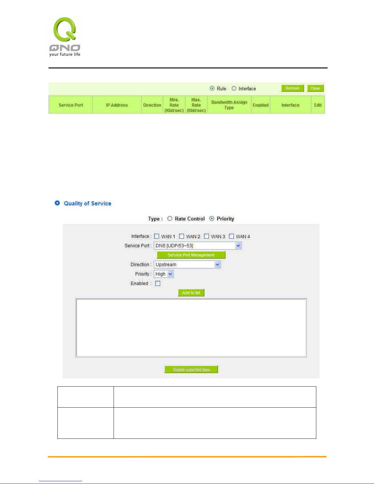
Enterprise Multi-WAN VPN QoS Router
72
Priority Control:
The Router will distribute the bandwidth as 60% (the highest) and 10% (the lowest). If
you set the service port 80 as “High” priority, the router will give 60% bandwidth to the port
80. In the other hand, if you give the port 21 as “Low” priority, the device will only give it
10% bandwidth. The remained 30% bandwidth will be shared by the other service.
Interface:
Select on which WAN the QoS rule should be executed. It can be a
single selection or multiple selections.
Service Port:
Select what bandwidth control is to be configured in the QoS rule. If
FTP uploads or downloads need to be controlled, select “FTP Port
21~21”. Refer to the Default Service Port Number List.
Page 80

Enterprise Multi-WAN VPN QoS Router
73
Direction:
Upstream: Means the upload bandwidth for Intranet IP.
Downstream: Means the download bandwidth for Intranet IP.
Server in LAN, Upstream: If a Server for external connection has
been built in the device, this option is to control the bandwidth for the
traffic coming from outside to this Server.
Server in LAN, Downstream: If there are web sites built in the
Intranet, this option is to control the upload bandwidth for the
connections from outside to this Server. For example, game servers
have been built in many Internet cafés. This rule can be used to
control the bandwidth for connections from outside to the game
server of a café to update data. In this way, game players inside the
café will not be affected.
Priority:
High: 60% guaranteed bandwidth to the service
Low: Only 10% bandwidth offered to the service
Enabled:
Activate the rule.
Add to list:
Add this rule to the list.
Delete Selected
items:
Remove the rules selected from the Service List.
Show Table:
This will display all the Priority Rules users made for the bandwidth.
Click “Edit” to modify.
Apply:
Click “Apply” to save the configuration
Cancel:
Click “Cancel" to leave without making any change.
Page 81
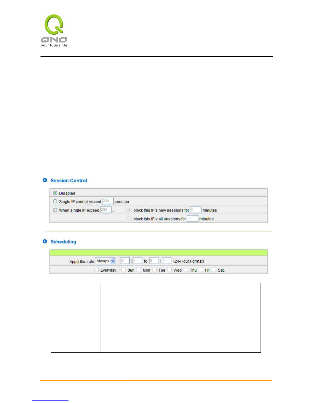
Enterprise Multi-WAN VPN QoS Router
74
8.2 Session control
Session management controls the acceptable maximum simultaneous sessions of
Intranet PCs. This function is very useful for managing connection quantity when P2P
software such as BT, Thunder, or emule is used in the Intranet causing large numbers of
sessions. Setting up proper limitations on sessions can effectively control the sessions
created by P2P software. It will also have a limiting effect on bandwidth usage.
In addition, if any Intranet PC is attacked by a virus like Worm.Blaster and sends a huge
number of session requests, session control will restrict that as well.
Session Control and Scheduling:
Disabled:
Disable Session Control function.
Single IP cannot
exceed __
session:
This option enables the restriction of maximum external sessions
to each Intranet PC. When the number of external sessions
reaches the limit, to allow new sessions to be built, some of the
existing sessions must be closed. For example, when BT or P2P is
being used to download information and the sessions exceed the
limit, the user will be unable to connect with other services until
either BT or P2P is closed.
Page 82
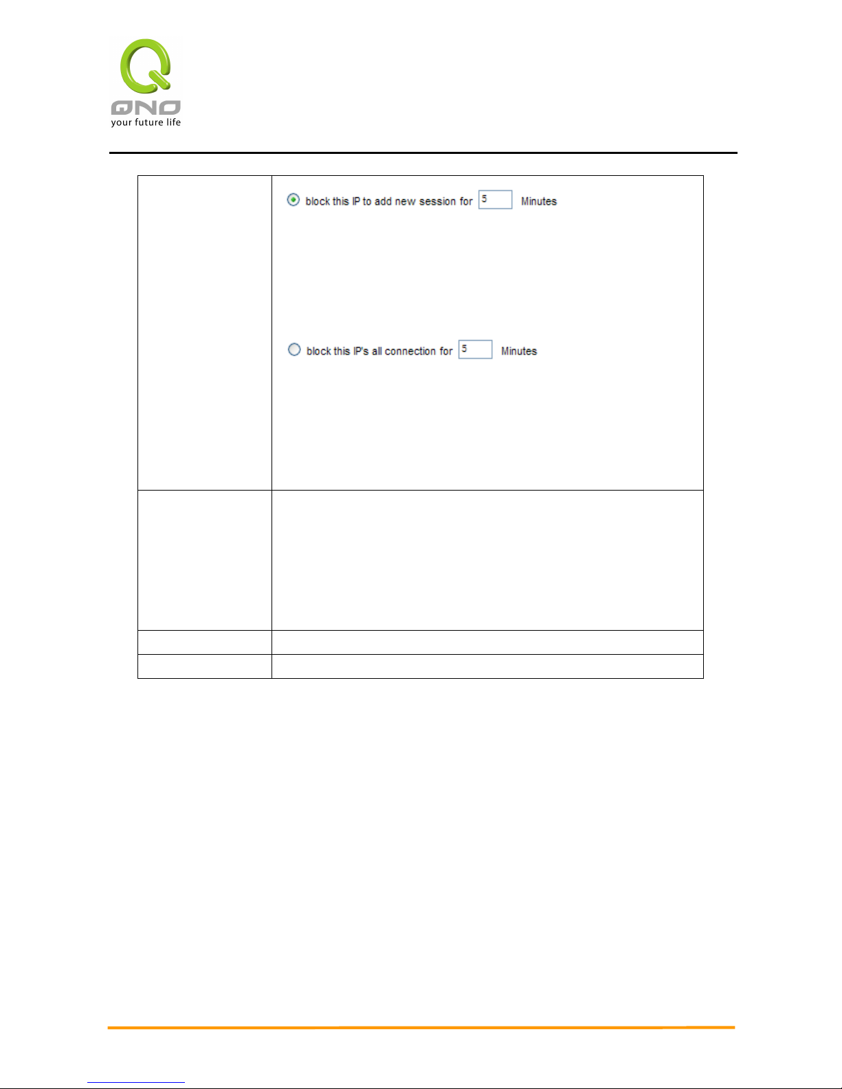
Enterprise Multi-WAN VPN QoS Router
75
When single IP
exceed __:
If this function is selected, when the user’s port session reach
the limit, this user will not be able to make a new session for five
minutes. Even if the previous session has been closed, new
sessions cannot be made until the setting time ends.
If this function is selected, when the user’s port connections
reach the limit, all the lines that this user is connected with will be
removed, and the user will not be able to connect with the
Internet for five minutes. New connections cannot be made until
the delay time ends.
Scheduling:
If “Always” is selected, the rule will be executed around the
clock.
If “From…” is selected, the rule will be executed according to the
configured time range. For example, if the time control is from
Monday to Friday, 8:00am to 6:00pm, users can refer to the
following figure to set up the rule.
Apply:
Click “Apply” to save the configuration.
Cancel:
Click “Cancel" to leave without making any change.
Exempted Service Port or IP Address
Page 83
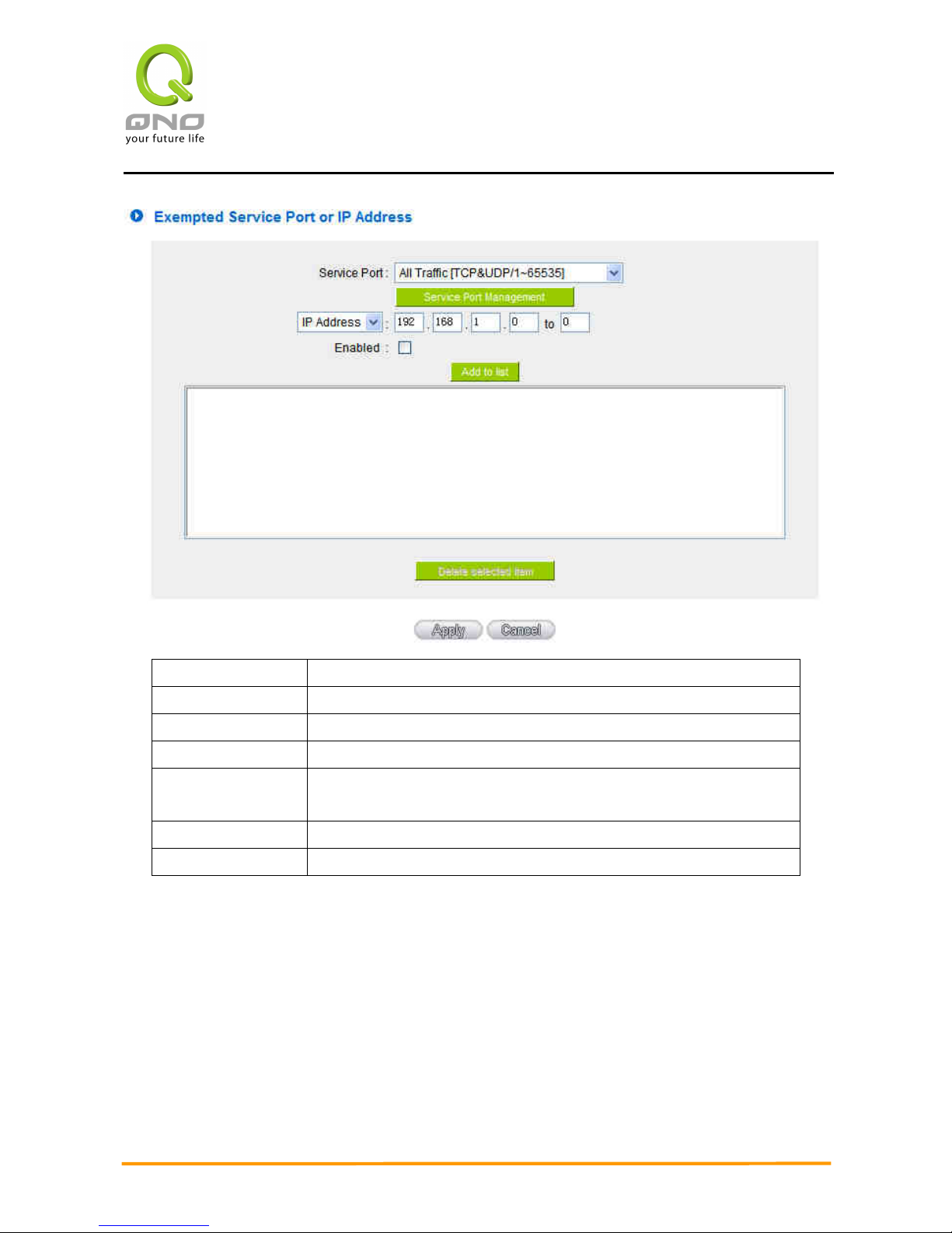
Enterprise Multi-WAN VPN QoS Router
76
Service Port:
Choose the service port.
IP Address:
Input the IP address range or IP group.
Enabled:
Activate the rule.
Add to list:
Add this rule to the list.
Delete seleted
item:
Remove the rules selected from the Service List.
Apply:
Click “Apply” to save the configuration.
Cancel:
Click “Cancel" to leave without making any change.
Page 84
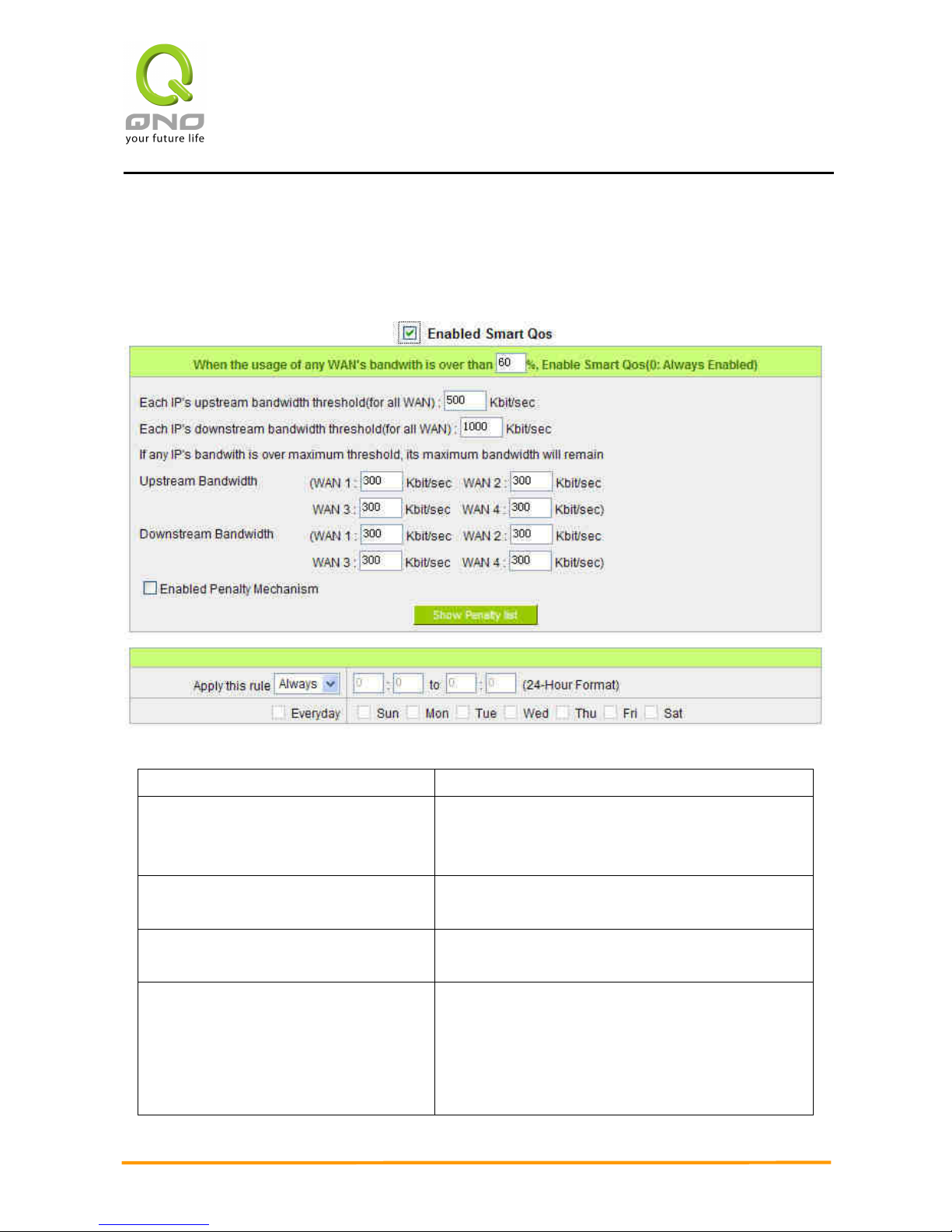
Enterprise Multi-WAN VPN QoS Router
77
8.3 Smart QoS
The smart QoS function enables the administrators to constrain the bandwidth occupied
automatically without any configuring.
Enabled Smart Qos To activate the Smart QoS function.
When the usage of any WAN's
bandwith is over than __ %, Enable
Smart Qos(0: Always Enabled)
When the usage of any WAN's bandwith is over
than __ %, Smart QoS will be enabled. You can
enter the needed value, the default is 60%.
Each IP's upstream bandwidth
threshold(for all WAN)
Input the allowed maximum threshold.
Each IP's downstream bandwidth
threshold(for all WAN)
Input the allowed maximum threshold.
If any IP's bandwith is over maximum
threshold, its maximum bandwidth will
remain
WAN1:__kbit/sec WAN2:__kbit/sec
WAN3:__kbit/sec WAN4:__kbit/sec
If any IP's bandwith is over maximum threshold,
the penalty mechanism will be activated. After
being punished, its maximum
upstream/downstream bandwidth will remain as a
determined value.
Page 85

Enterprise Multi-WAN VPN QoS Router
78
Enabled Penalty Mechanism To activate the penalty mechanism.
Show Penalty List
To show the IPs with upstream constraint、
downstream constraint and in the penalty
mechanism.
Applied Time If “Always” is selected, the rule will be executed
around the clock. If “From…” is selected, the rule
will be executed according to the configured time
range.
Page 86
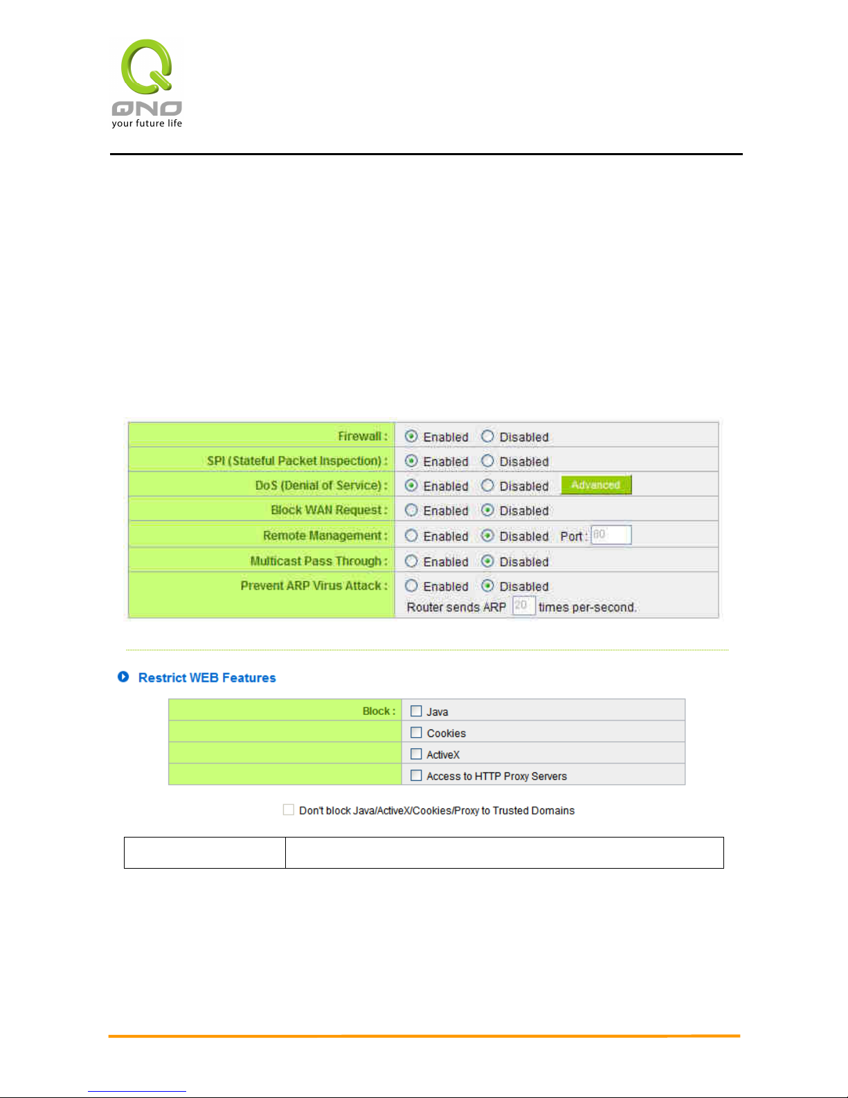
Enterprise Multi-WAN VPN QoS Router
79
IX. Firewall
This chapter introduces firewall general policy, access rule, and content filter settings to
ensure network security.
9.1 General Policy
The firewall is enabled by default. If the firewall is set as disabled, features such as SPI,
DoS, and outbound packet responses will be turned off automatically. Meanwhile, the remote
management feature will be activated. The network access rules and content filter will be
turned off.
Firewall:
This feature allows users to turn on/off the firewall.
Page 87

Enterprise Multi-WAN VPN QoS Router
80
SPI (Stateful Packet
Inspection):
This enables the packet automatic authentication detection
technology. The Firewall operates mainly at the network layer. By
executing the dynamic authentication for each connection, it will
also perform an alarming function for application procedure.
Meanwhile, the packet authentication firewall may decline the
connections which use non-standard communication protocol.
DoS (Denial of
Service):
This averts DoS attacks such as SYN Flooding, Smurf, LAND, Ping
of Death, IP Spoofing and so on.
Block WAN request:
If set as Enabled, then it will shut down outbound ICMP and
abnormal packet responses in connection. If users try to ping the
WAN IP from the external, this will not work because the default
value is set as activated in order to decline the outbound
responses.
Remote Management:
To enter the device web- based UI by connecting to the remote
Internet, this feature must be activated. In the field of remote
browser IP, a valid external IP address (WAN IP) for the device
should be filled in and the modifiable default control port should
be adjusted (the default is set to 80, modifiable).
Multicast Pass
Through:
There are many audio and visual streaming media on the
network. Broadcasting may allow the client end to receive this
type of packet message format. This feature is off by default.
Prevent ARP Virus
Attack:
This feature is designed to prevent the intranet from being
attacked by ARP spoofing, causing the connection failure of the
PC. This ARP virus cheat mostly occurs in Internet cafes. When
attacked, all the online computers disconnect immediately or
some computers fail to go online. Activating this feature may
prevent the attack by this type of virus.
Page 88
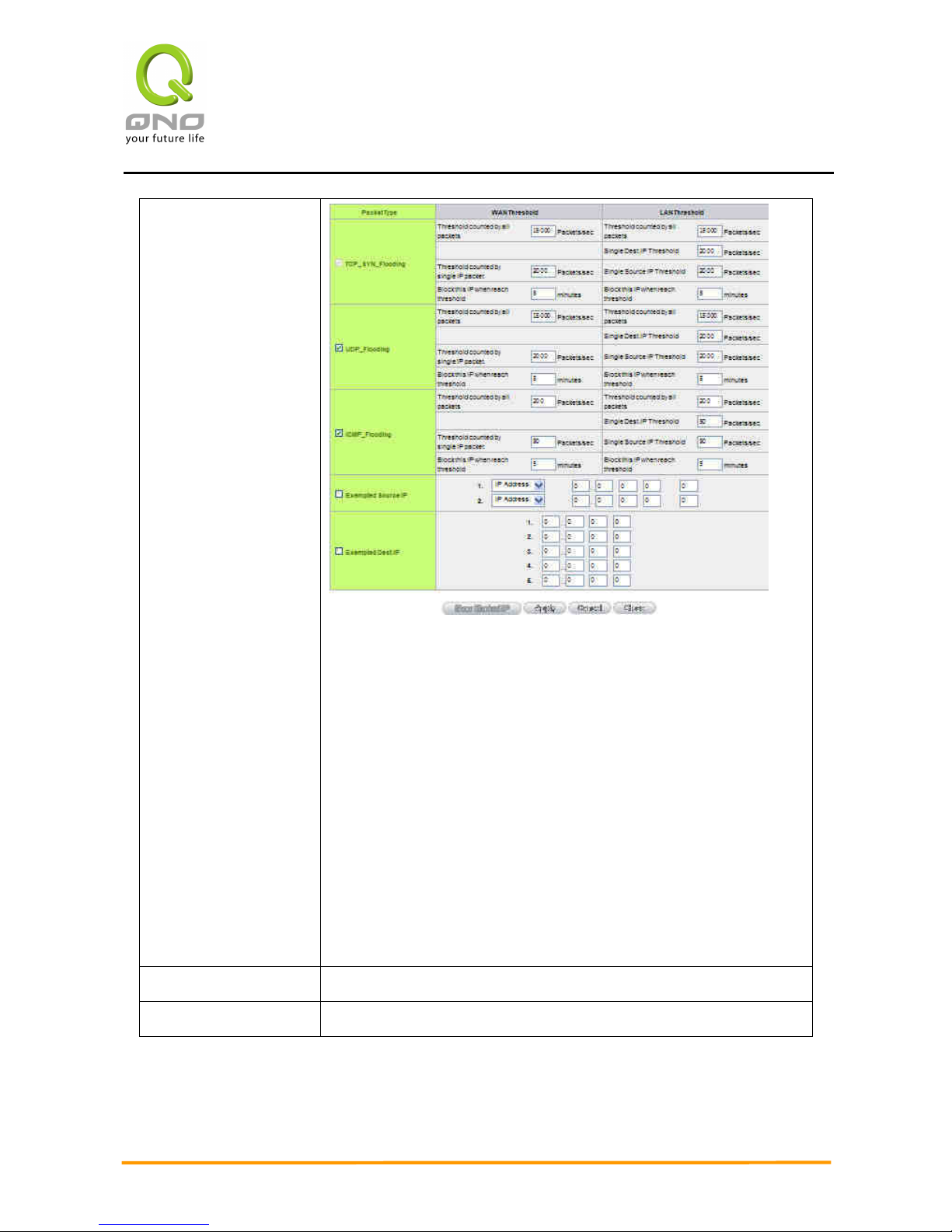
Enterprise Multi-WAN VPN QoS Router
81
Advanced Setting
Packet Type: This device provides three types of data packet
transmission: TCP-SYN-Flood, UDP-Flood and ICMP-Flood.
WAN Threshold: When all packet values from external attack or
from single external IP attack reach the maximum amount (the
default is 15000 packets/Sec and 2000 packets/Sec
respectively), if these conditions above occurs, the IP will be
blocked for 5 minutes ( the default is 5 minutes OBJ 176 ). Users
can adjust the threshold value and the blocking duration to
effectively deal with external attack. The threshold value should
be adjusted from high to low.
LAN Threshold: When all packet values from internal attack or
from single internal IP attack reach the maximum amount (the
default is 15000 packets/Sec and 2000 packets/Sec
respectively), if these conditions above occurs, the IP will be
blocked for 5 minutes (the default is 5 minutes). Users can
adjust the threshold value and the blocking duration to
effectively deal with external attack. The threshold value should
be adjusted from high to low.
Exempted Source IP:
Input the exempted source IP.
Exempted Dest. IP:
Input the exempted Destination IP addresses.
Page 89
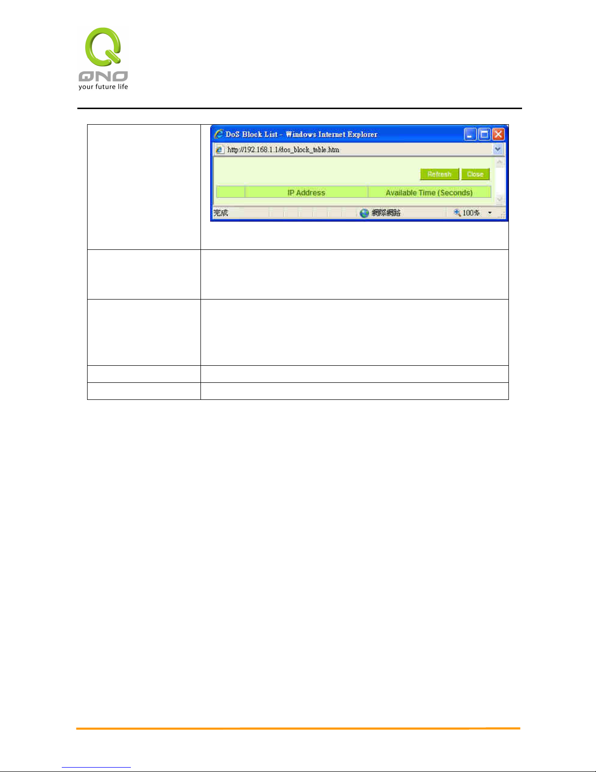
Enterprise Multi-WAN VPN QoS Router
82
Show Blocked IP:
Show the blocked IP list and the remained blocked time.
Restricted WEB
Features:
It supports the block that is connected through: Java, Cookies,
Active X, and HTTP Proxy access.
Don’t Block Java /
ActiveX / Cookies
Proxy to Trusted
Domain:
If this option is activated, users can add trusted network or IP
address into the trust domain, and it will not block items such as
Java/ActiveX/Cookies contained in the web pages from the trust
domains.
Apply:
Click “Apply” to save the configuration.
Cancel:
Click “Cancel" to leave without making any change.
Page 90
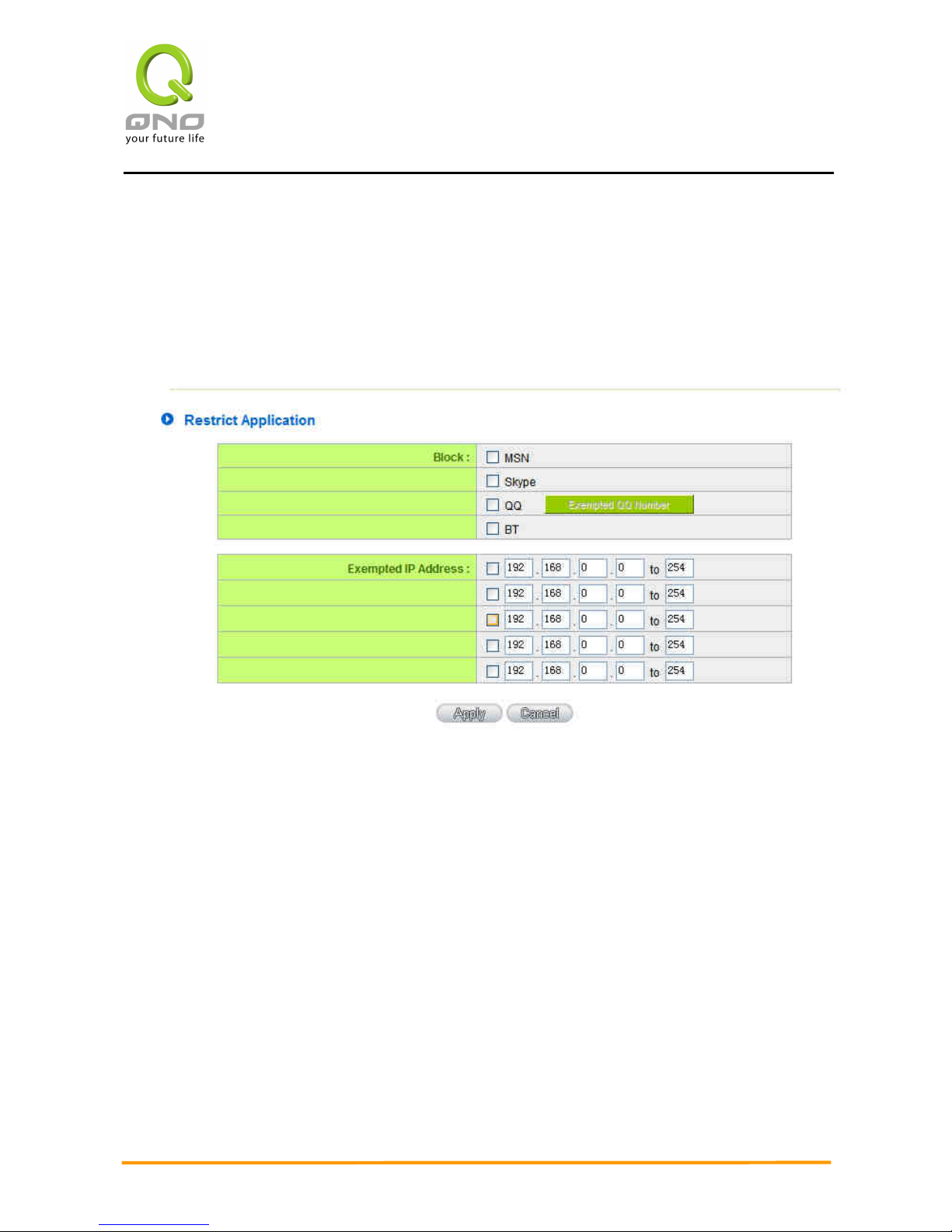
Enterprise Multi-WAN VPN QoS Router
83
9.2 Restrict Application
Users can check MSN/ Skype/ QQ/ BT and the device will block the service users
checked. However, to provide this service for certain IP address in the intranet, users may
check the following item and then enter the specific IP address or IP address session to use
the services which are checked above.
In addition, if Blocked QQ is activated, users can set the exempted QQ number list. Press
“Exempted QQ Number” button, and enter the QQ number into the exempted QQ number
list.
Page 91
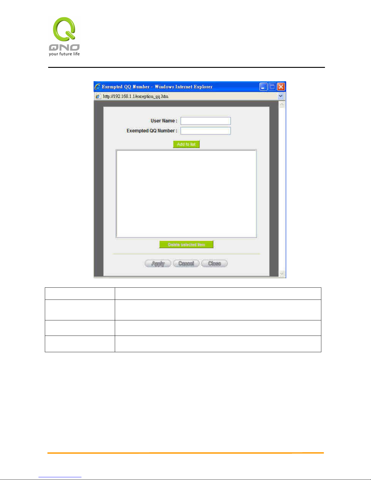
Enterprise Multi-WAN VPN QoS Router
84
User Name:
Input the information of the QQ number, etc.
Exempted QQ
Number:
Input the number.
Add to list:
Add the number to the list.
Delete selected item:
Delete the selected rule in the list.
Page 92

Enterprise Multi-WAN VPN QoS Router
85
9.3 Access Rule
Users may turn on/off the setting to permit or forbid any packet to access internet. Users
may select to set different network access rules: from internal to external or from external to
internal. Users may set different packets for IP address and communication port numbers to
filter Internet access rules.
Network access rule follows IP address, destination IP address, and IP communications
protocol status to manage the network packet traffic and make sure whether their access is
allowed by the firewall.
The device has a user-friendly network access regulatory tool. Users may define network
access rules. They can select to enable/ disable the network so as to protect all internet
access. The following describes the internet access rules:
All traffic from the LAN to the WAN is allowed - by default.
All traffic from the WAN to the LAN is denied - by default.
All traffic from the LAN to the DMZ is allowed - by default.
All traffic from the DMZ to the LAN is denied - by default.
All traffic from the WAN to the DMZ is allowed - by default.
All traffic from the DMZ to the WAN is allowed - by default.
Users may define access rules and do more than the default rules. However, the following
four extra service items are always on and are not affected by other user-defined settings.
* HTTP Service (from LAN to Device) is on by default (for management)
* DHCP Service (from LAN to Device) is set to on by default (for the automatic IP
retrieval)
* DNS Service (from LAN to Device) is on by default (for DNS service analysis)
* Ping Service (from LAN to Device) is on by default (for connection and test)
Page 93
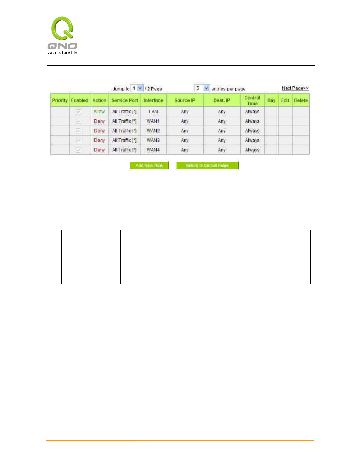
Enterprise Multi-WAN VPN QoS Router
86
In addition to the default rules, all the network access rules will be displayed as illustrated
above. Users may follow or self- define the priority of each network access rule. The device will
follow the rule priorities one by one, so please make sure the priority for all the rules can suit the
setting rules.
Edit:
Define the network access rule item
Delete:
Remove the item.
Add New Rule:
Create a new network access rule
Return to Default
Rule:
Restore all settings to the default values and delete all the
self-defined settings.
Page 94
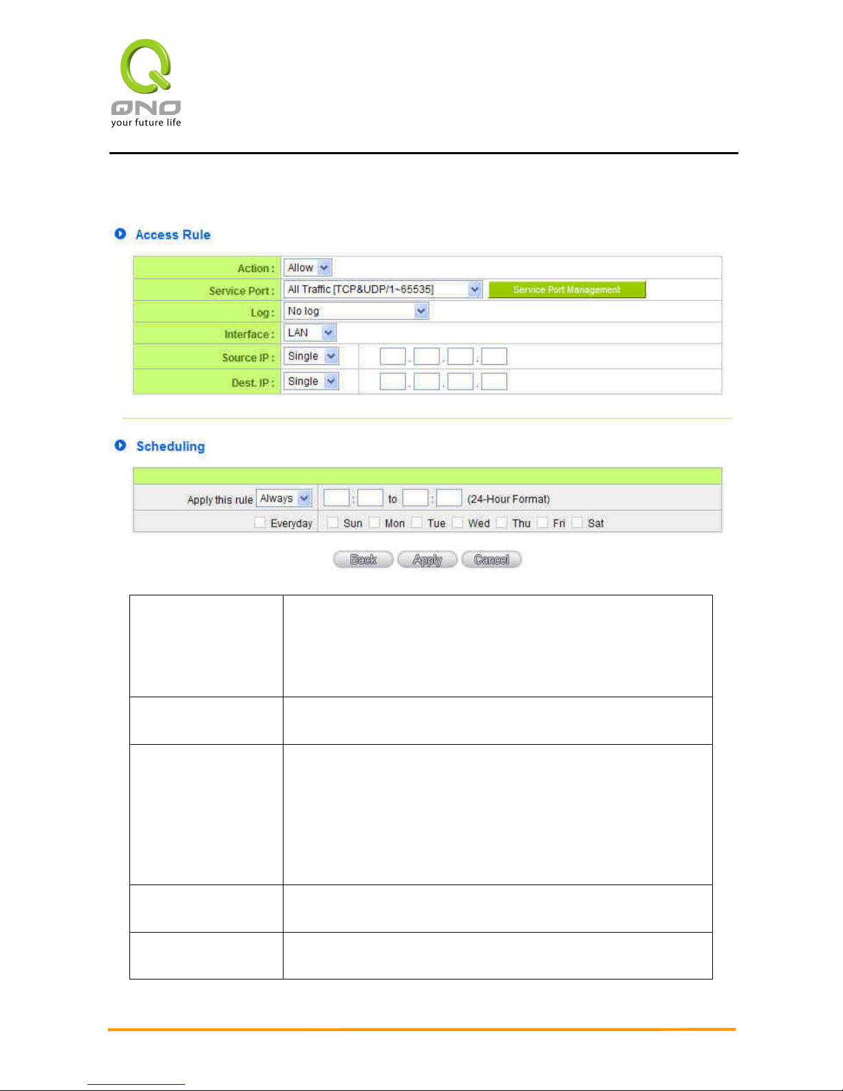
Enterprise Multi-WAN VPN QoS Router
87
9.3.2 Add New Access Rule
Action:
Allow: Permits the pass of packets compliant with this control
rule
Deny: Prevents the pass of packets not compliant with this
control rule
Service Port:
From the drop-down menu, select the service that users grant or
do not give permission.
Service Port
Management:
If the service that users wish to manage does not exist in the
drop-down menu, press – Service Management to add the new
service.
From the pop-up window, enter a service name and
communications protocol and port, and then click the “Add to
list” button to add the new service.
Log: No Log: There will be no log record.
Create Log when matched: Event will be recorded in the log.
Interface:
Select the source port whether users are permitted or not (for
example: LAN, WAN1, WAN2 or Any). Select from the drop-down
Page 95

Enterprise Multi-WAN VPN QoS Router
88
menu.
Source IP:
Select the source IP range (for example: Any, Single, Range, or
preset IP group name). If Single or Range is selected, please
enter a single IP address or an IP address within a session.
Dest. IP:
Select the destination IP range (such as Any, Single, Range, or
preset IP group name) If Single or Range is selected; please
enter a single IP address or an IP address within a session.
Scheduling:
Select “Always” to apply the rule on a round-the-clock basis.
Select “from”, and the operation will run according to the
defined time.
Apply this rule:
Select "Always" to apply the rule on a round-the-clock basis.
If “From” is selected, the activation time is introduced as below
… to … :
This control rule has time limitation. The setting method is in
24-hour format, such as 08:00 ~ 18:00 (8 a.m. to 6 p.m.)
Day Control:
”Everyday” means this period of time will be under control
everyday. If users only certain days of a week should be under
control, users may select the desired days directly.
Apply:
Click “Apply” to save the configuration.
Cancel:
Click “Cancel" to leave without making any change.
Page 96
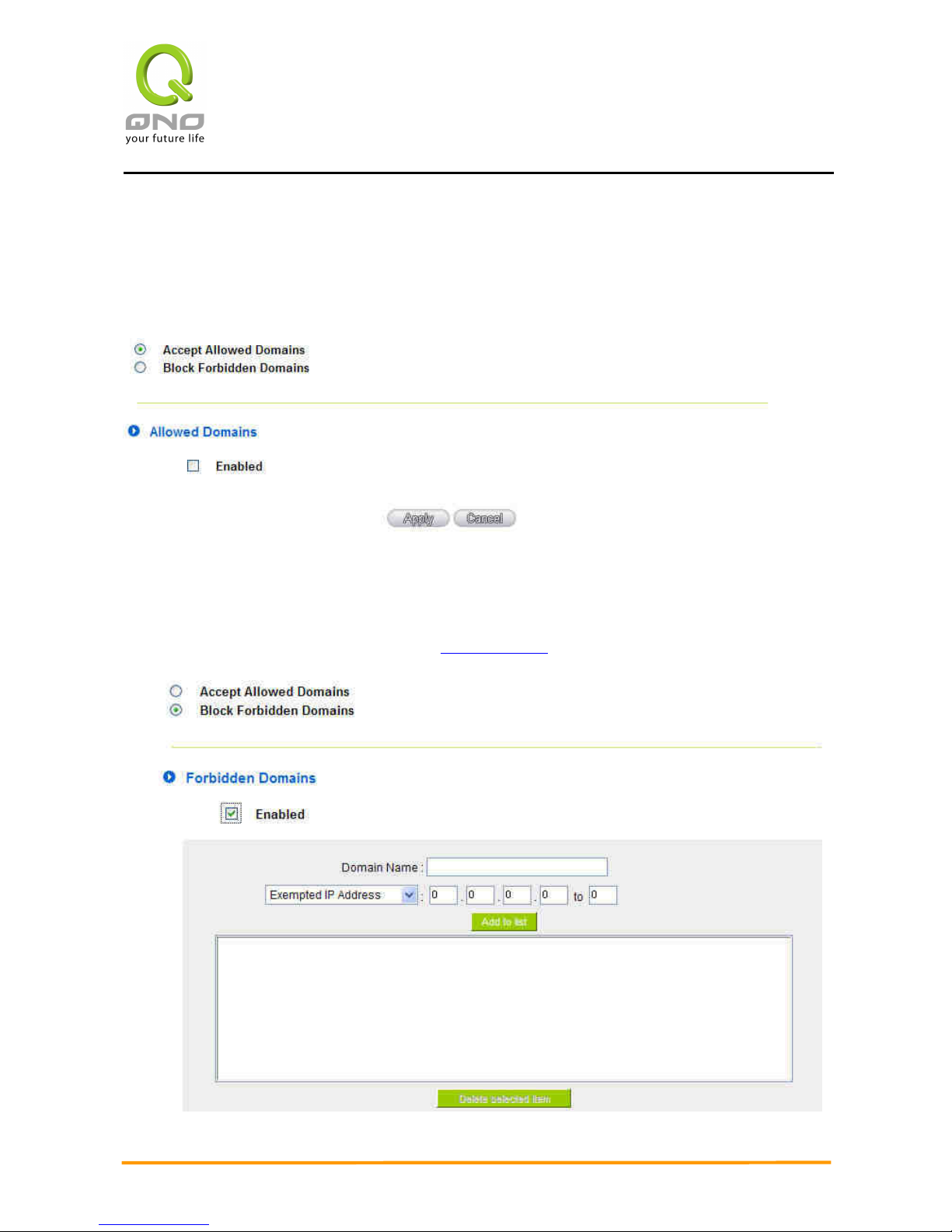
Enterprise Multi-WAN VPN QoS Router
89
9.4 Content Filter
The device supports two webpage restriction modes: one is to block certain forbidden
domains, and the other is to give access to certain web pages. Only one of these two modes can
be selected.
Block Forbidden Domain
Fill in the complete website such as www.sex.com to have it blocked.
Page 97
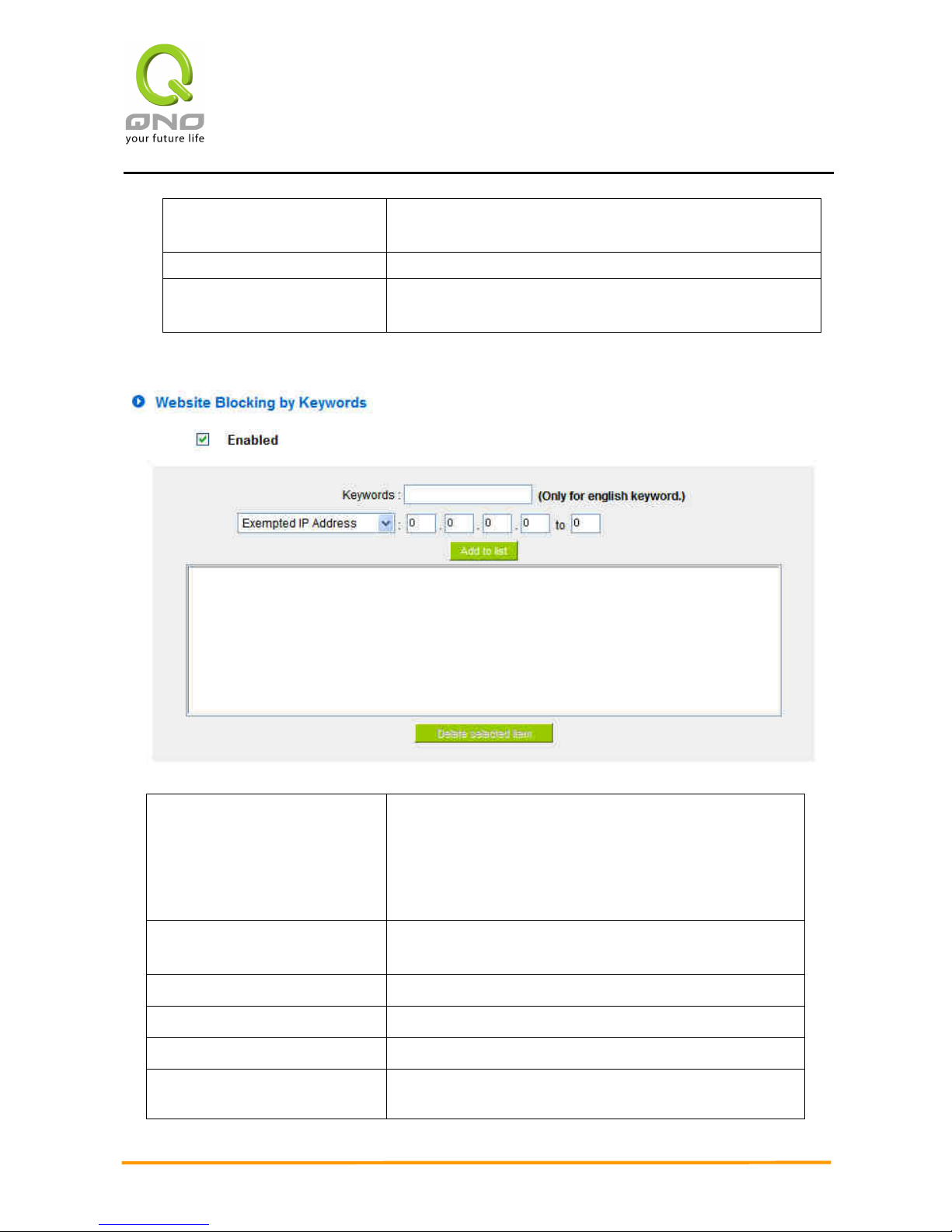
Enterprise Multi-WAN VPN QoS Router
90
Domain Name:
Enter the websites to be controlled such as
www.playboy.com
Add to list:
Click ”Add to list” to create a new website to be controlled.
Delete selected item:
Click to select one or more controlled websites and click
this option to delete.
Website Blocking by Keywords:
Enabled:
Click to activate this feature. The default setting is
disabled. For example: If users enter the string ”sex”,
any websites containing ”sex” will be blocked.
Keywords(Only for English
keyword):
Enter keywords.
Add to List:
Add this new service item content to the list.
Delete selected item:
Delete the service item content from the list
Apply:
Click “Apply” to save the modified parameters.
Cancel:
Click “Cancel” to cancel all the changes made to the
parameters.
Page 98
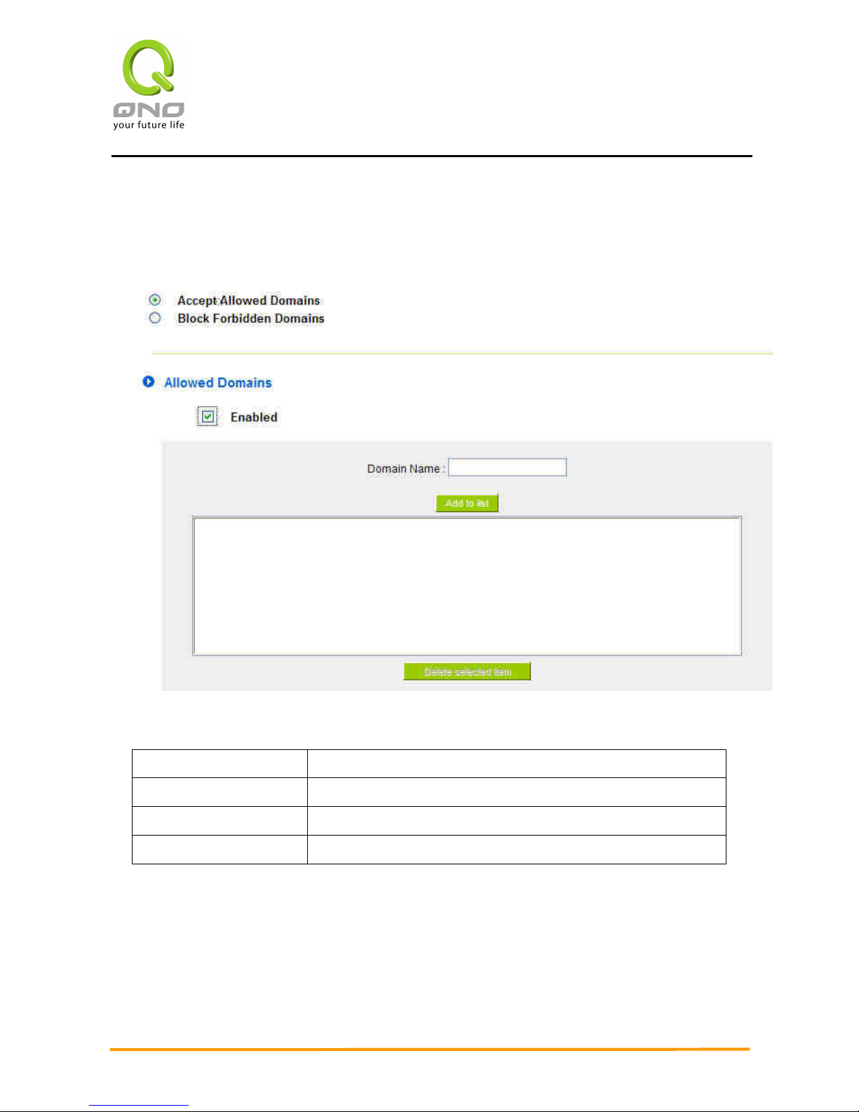
Enterprise Multi-WAN VPN QoS Router
91
Accept Allowed Domains
In some companies or schools, employees and students are only allowed to access some
specific websites. This is the purpose of the function.
Enabled:
Activate the function. The default setting is “Disabled.”
Domain Name:
Input the allowed domain name, etc. www.google.com
Add to list:
Add the rule to list.
Delete selected item:
Users can select one or more rules and click to delete.
Content Filter Scheduling
Select “Always” to apply the rule on a round-the-clock basis. Select “from”, and the
operation will run according to the defined time. For example, if the control time runs from 8
a.m. to 6 p.m., Monday to Friday, users may control the operation according to the following
illustrated example.
Page 99
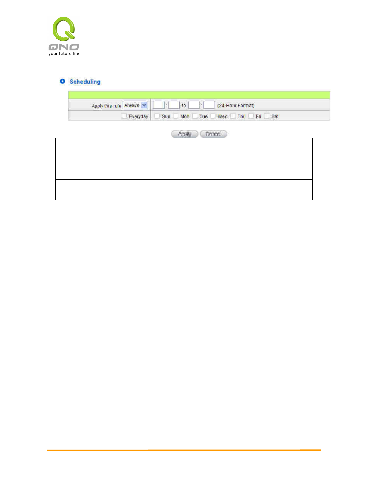
Enterprise Multi-WAN VPN QoS Router
92
Always:
Select “Always” to apply the rule on a round-the-clock basis. Select
“from”, and the operation will run according to the defined time.
…to…:
Select "Always" to apply the rule on a round-the-clock basis.
If “From” is selected, the activation time is introduced as below
Day Control:
This control rule has time limitation. The setting method is in 24-hour
format, such as 08:00 ~ 18:00 (8 a.m. to 6 p.m.)
Page 100
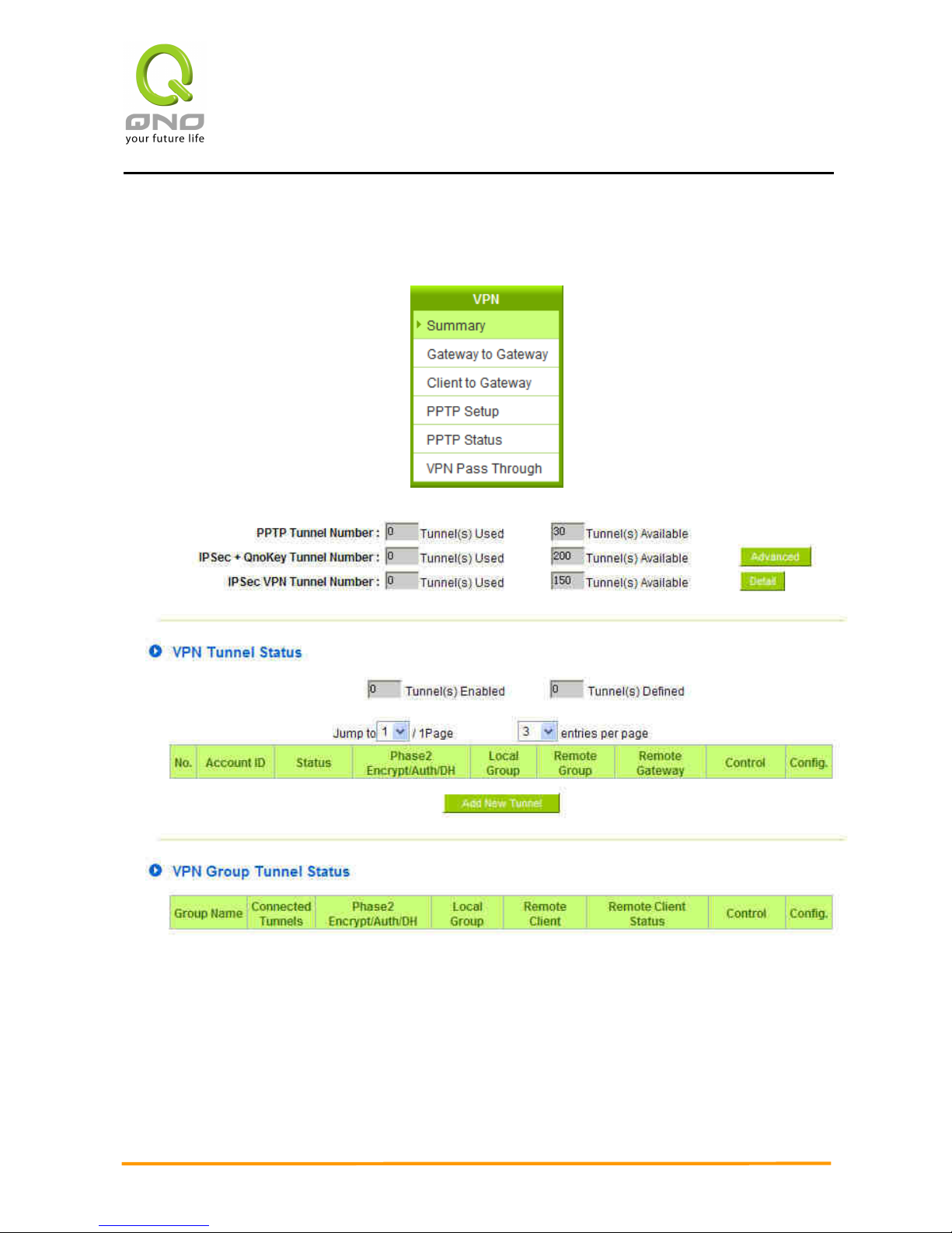
Enterprise Multi-WAN VPN QoS Router
93
X. VPN (Virtual Private Network)
10.1. VPN
10.1.1. Display All VPN Summary
This VPN Summary displays the real-time data with regard to VPN status. These data
include: all tunnel numbers (PPTP, IPSec + QnoKey and IPSec VPN), setting parameters and
Group VPN and so forth.
 Loading...