

Page 1

VioStor NVR
Network Video Recorder
User Manual (Version: 3.6.0)
© 2012. QNAP Systems, Inc. All Rights Reserved.
Page 2

2
Thank you for choosing QNAP products! This user manual provides detailed instructions of
using the product. Please read carefully and start to enjoy the powerful functions of the
product!
The VioStor NVR is hereafter referred to as the VioStor or the NVR.
This user manual provides the description of all the functions of the VioStor NVR. The
product you purchased may not support certain functions dedicated to specific models.
This user manual (version 3.6.0) is applicable for the VioStor NVR firmware version
3.6.0 only. If the VioStor NVR is running an older firmware version, please refer to the
previous versions of the user manuals.
Legal Notices
All the features, functionality, and other product specifications are subject to change
without prior notice or obligation. Information contained herein is subject to change
without notice.
QNAP and the QNAP logo are trademarks of QNAP Systems, Inc. All other brands and
product names referred to are trademarks of their respective holders.
Further, the ® or ™ symbols are not used in the text.
LIMITED WARRANTY
In no event shall the liability of QNAP Systems, Inc. (QNAP) exceed the price paid for the
product from direct, indirect, special, incidental, or consequential software, or its
documentation. QNAP makes no warranty or representation, expressed, implied, or
statutory, with respect to its products or the contents or use of this documentation and all
accompanying software, and specifically disclaims its quality, performance,
merchantability, or fitness for any particular purpose. QNAP reserves the right to revise or
update its products, software, or documentation without obligation to notify any individual
or entity.
CAUTION
1. Back up the system periodically to avoid any potential data loss. QNAP disclaims any
responsibility of all sorts of data loss or recovery.
2. Should you return any components of the product package for refund or maintenance,
make sure they are carefully packed for shipping. Any form of damages due to
improper packaging will not be compensated.
Page 3

3
Important Notice
Reading instructions
Please read the safety warnings and user manual carefully before using this product.
Power supply
This product can only be used with the power supply provided by the manufacturer.
Service
Please contact qualified technicians for any technical enquires. Do not repair this
product by yourself to avoid any voltage danger and other risks caused by opening this
product cover.
Warning
To avoid fire or electric shock, do not use this product in rain or humid environment.
Do not place any objects on this product.
Page 4

4
Regulatory Notice
FCC STATEMENT
This equipment has been tested and found to comply with the limits for a Class B digital
device, pursuant to Part 15 of FCC Rules. These limits are designed to provide reasonable
protection against harmful interference in a residential installation. This equipment
generates, uses, and can radiate radio frequency energy and, if not installed and used in
accordance with the instructions, may cause harmful interference to radio communications.
However, there is no guarantee that interference will not occur in particular installation. If
this equipment does cause harmful interference to radio or television reception, which can
be determined by turning the equipment off and on, the user is encouraged to try to correct
the interference by one or more of the following measures:
Reorient or relocate the receiving antenna.
Increase the separation between the equipment and receiver.
Connect the equipment into an outlet on a circuit different from that to which the
receiver is connected.
Consult the dealer or an experienced radio/television technician for help.
The changes or modifications not expressly approved by the party responsible for
compliance could void the user's authority to operate the equipment.
Shielded interface cables, if any, must be used in order to comply with the emission limits.
CE NOTICE
Class B only.
Page 5

5
Table of Contents
TABLE OF CONTENTS ..................................................................................................................................... 5
SAFETY WARNING ........................................................................................................................................... 9
CHAPTER 1. INTRODUCTION .............................................................................................................. 10
1.1 OVERVIEW ............................................................................................................................................. 10
1.2 HARDWARE ILLUSTRATION ................................................................................................................... 11
1.2.1 VS-12164U-RP Pro/VS-12156U-RP Pro/VS-12148U-RP Pro/VS-12140 U-RP Pro
11
1.2.2 VS-8148U-RP Pro/VS-8140U-RP Pro/VS-8132U-RP Pro/VS-8124U-RP Pro .... 13
1.2.3 VS-8148 Pro+/VS-8140 Pro+/VS-8132 Pro+/VS-8124 Pro+ ............................... 14
1.2.4 VS-8040U-RP/VS-8032U-RP/VS-8024U-RP ................................................................. 15
1.2.5 VS-8040/VS-8032/VS-8024 ............................................................................................... 16
1.2.6 VS-6020 Pro/VS-6016 Pro/VS-6012 Pro ....................................................................... 17
1.2.7 VS-4016U-RP Pro/VS-4012U-RP Pro/VS-4008U-RP Pro ......................................... 18
1.2.8 VS-4016 Pro/VS-4012 Pro/VS-4008 Pro ....................................................................... 19
1.2.9 VS-4016U-RP ........................................................................................................................... 20
1.2.10 VS-2012 Pro/VS-2008 Pro/VS-2004 Pro ....................................................................... 21
1.2.11 VS-2012/VS-2008 .................................................................................................................. 22
1.2.12 VS-2004L/VS-2008L ............................................................................................................. 23
1.2.13 VS-1004L ................................................................ ................................................................ ... 24
CHAPTER 2. INSTALL THE NVR .......................................................................................................... 25
2.1 PERSONAL COMPUTER REQUIREMENTS ................................................................................................. 26
2.2 BROWSE CD-ROM ................................................................................................................................ 28
2.3 HARD DISK DRIVES COMPATIBILITY LIST ............................................................................................. 30
2.4 IP CAMERAS COMPATIBILITY LIST ........................................................................................................ 30
2.5 CHECK SYSTEM STATUS ........................................................................................................................ 31
2.6 SYSTEM CONFIGURATION ...................................................................................................................... 34
CHAPTER 3. USE THE NVR BY LOCAL DISPLAY ........................................................................... 38
3.1 QUICK CONFIGURATION ........................................................................................................................ 40
3.2 SYSTEM CONFIGURATION ...................................................................................................................... 47
3.3 MONITORING ......................................................................................................................................... 49
3.4 VIDEO PLAYBACK ................................................................................................................................. 60
3.5 VIDEO CONVERSION & EXPORT ............................................................................................................ 62
Page 6

6
CHAPTER 4. USE THE NVR BY WEB-BASED INTERFACE ............................................................ 64
4.1 CONNECT TO THE NVR ......................................................................................................................... 64
4.2 MONITORING PAGE ............................................................................................................................... 66
4.2.1 Live Video Window ................................................................................................................. 75
4.2.2 Display Mode ............................................................................................................................ 77
4.2.3 PTZ Camera Control Panel .................................................................................................. 77
4.2.4 Multi-server Monitoring ........................................................................................................ 78
4.2.5 Monitor Settings ..................................................................................................................... 79
4.2.6 Auto Cruising ........................................................................................................................... 83
4.3 E-MAP ................................................................................................................................................... 87
4.3.1 Icons and Description ........................................................................................................... 89
4.3.2 Add a Map Set or an E-map ............................................................................................... 90
4.3.3 Edit a Map Name .................................................................................................................... 93
4.3.4 Delete a Map Set or an E-map .......................................................................................... 93
4.3.5 Indicate IP Cameras on an E-map ................................................................ ................... 94
4.3.6 Enable/Disable Event Alert ................................................................................................. 96
CHAPTER 5. PLAY VIDEO FILES ......................................................................................................... 99
5.1 USE WEB-BASED VIOSTOR PLAYER .................................................................................................... 100
5.1.1 Play Video Files from NVR ................................................................................................. 103
5.1.2 Play Video Files from Local PC ........................................................................................ 115
5.1.3 Multi-view Playback ............................................................................................................. 120
5.1.4 Intelligent Video Analytics (IVA) .................................................................................... 128
5.1.5 Convert NVR Videos to an AVI File ................................................................................ 135
5.2 DIGITAL WATERMARKING ................................................................................................................... 139
5.2.1 Export Video Files with Digital Watermark ................................................................. 139
5.2.2 Watermark Proof .................................................................................................................. 141
5.3 ACCESS THE RECORDING DATA........................................................................................................... 143
5.3.1 Microsoft Networking (SMB/CIFS) ................................................................................. 144
5.3.2 Web File Manager (HTTP) ................................................................................................. 144
5.3.3 FTP Server (FTP) .................................................................................................................. 145
CHAPTER 6. SYSTEM ADMINISTRATION ....................................................................................... 146
6.1 QUICK CONFIGURATION ...................................................................................................................... 149
6.2 SYSTEM SETTINGS ............................................................................................................................... 156
6.2.1 Server Name .......................................................................................................................... 156
6.2.2 Date & Time ........................................................................................................................... 157
6.2.3 View System Settings ......................................................................................................... 158
6.3 NETWORK SETTINGS ........................................................................................................................... 159
Page 7

7
6.3.1 TCP/IP Configuration .......................................................................................................... 159
6.3.2 DDNS (Dynamic Domain Name) Service .................................................................... 165
6.3.3 File Services ........................................................................................................................... 166
6.3.4 Host Access Control............................................................................................................. 167
6.3.5 Protocol Management ......................................................................................................... 168
6.3.6 View Network Settings ....................................................................................................... 169
6.4 DEVICE CONFIGURATION .................................................................................................................... 170
6.4.1 SATA Disk ................................................................................................................................ 170
6.4.2 RAID Management Tool ..................................................................................................... 174
6.4.3 USB Disk .................................................................................................................................. 176
6.4.4 UPS ............................................................................................................................................ 177
6.5 USER MANAGEMENT ........................................................................................................................... 178
6.5.1 Create user ............................................................................................................................. 180
6.5.2 Edit User .................................................................................................................................. 181
6.5.3 Delete User ............................................................................................................................. 181
6.5.4 User Access Rights Comparison ..................................................................................... 182
6.6 CAMERA SETTINGS ................................................................ .............................................................. 185
6.6.1 Camera Configuration ........................................................................................................ 185
6.6.2 Recording Settings ............................................................................................................... 188
6.6.3 Schedule Settings ................................................................................................................ 190
6.6.4 Alarm Settings ....................................................................................................................... 191
6.6.5 Advanced Settings ............................................................................................................... 209
6.7 SYSTEM TOOLS .................................................................................................................................... 211
6.7.1 Alert Notification ................................................................................................................... 211
6.7.2 SMSC Settings ....................................................................................................................... 212
6.7.3 Restart/Shut Down .............................................................................................................. 214
6.7.4 Hardware Settings ............................................................................................................... 215
6.7.5 System Update ...................................................................................................................... 217
6.7.6 Back up/Restore/Reset Settings ..................................................................................... 218
6.7.7 Remote Replication .............................................................................................................. 219
6.7.8 Hard Disk SMART ................................................................................................................. 223
6.7.9 Ping Test .................................................................................................................................. 224
6.7.10 Advanced System Settings ............................................................................................... 225
6.8 LOGS & STATISTICS ............................................................................................................................. 226
6.8.1 System Event Logs .............................................................................................................. 226
6.8.2 Surveillance Logs ................................................................................................................. 227
6.8.3 On-line Users List ................................................................................................................. 228
6.8.4 Historical Users List ............................................................................................................. 228
Page 8

8
6.8.5 System Connection Logs ................................ ................................................................ ... 229
6.8.6 System Information ............................................................................................................ 229
CHAPTER 7. SYSTEM MAINTENANCE ............................................................................................ 230
7.1 RESET THE ADMINISTRATOR PASSWORD AND NETWORK SETTINGS .................................................... 230
7.2 POWER OUTAGE OR ABNORMAL SHUTDOWN ...................................................................................... 231
7.3 HOT SWAPPING HARD DISK DRIVES (RAID CONFIGURATION) ........................................................... 231
CHAPTER 8. LCD PANEL ..................................................................................................................... 232
CHAPTER 9. TROUBLESHOOTING ................................................................................................... 238
APPENDIX A DYNAMIC DOMAIN NAME REGISTRATION .......................................................... 241
APPENDIX B CONFIGURATION EXAMPLES ................................................................................... 246
TECHNICAL SUPPORT ................................................................................................................................ 251
GNU GENERAL PUBLIC LICENSE ............................................................................................................ 252
Page 9

9
Safety Warning
1. This product can operate normally in the temperature of 0ºC–40ºC and relative
humidity of 0%–90%. Please make sure the environment is well-ventilated.
2. The power cord and devices connected to this product must provide correct supply
voltage.
3. Do not place this product in direct sunlight or near chemicals. Make sure the
temperature and humidity of the environment are in optimized level.
4. Unplug the power cord and all connected cables before cleaning. Wipe this product
with a wet towel. Do not use chemical or aerosol to clean this product.
5. Do not place any objects on this product for the server's normal operation and to avoid
overheat.
6. Use the flat head screws in the product package to lock the hard disks in this product
when installing hard disks for proper operation.
7. Do not place this product near any liquid.
8. Do not place this product on any uneven surface to avoid falling off and damage.
9. Make sure the voltage is correct in your location when using this product. If you are
not sure about the voltage, please contact the distributor or the local power supply
company.
10. Do not place any object on the power cord.
11. Do not attempt to repair this product in any occasions. Improper disassembly of the
product may expose you to electric shock or other risks. For any enquiries, please
contact the distributor.
12. The chassis models should only be installed in the server room and maintained by the
authorized server manager or IT administrator. The server room is locked by key or
keycard access and only certified staff is allowed to enter the server room.
Warning:
Danger of explosion if battery is incorrectly replaced. Replace only with the same or
equivalent type recommended by the manufacturer. Dispose of used batteries
according to the manufacturer's instructions.
Do NOT touch the fan inside the system to avoid serious injuries.
Page 10

10
Chapter 1. Introduction
1.1 Overview
The QNAP VioStor NVR (hereafter referred to as the NVR or the VioStor) is the high
performance network surveillance solution for network-based monitoring of IP cameras,
video recording, playback, and remote data access. Up to 128 channels from multiple
QNAP NVR servers can be monitored simultaneously. The NVR supports IP-based cameras
and video servers from numerous brands, for more information please visit
http://www.qnapsecurity.com/pro_compatibility_camera.asp.
The NVR supports video recording in H.264, MxPEG, MPEG-4, or MJPEG video compression.
The NVR offers diversified display modes and recording features, e.g. scheduled recording,
alarm recording, alarm recording schedule. The NVR also supports data search by date
and time, timeline, event, and intelligent video analytics (IVA), including motion detection,
missing object, foreign object, out of focus, and camera occlusion. All the functions can be
configured by an IE web browser.
The VioStor Pro Series NVR is the world's first Linux-based NVR capable of truly PC-less
quick configuration, monitoring of IP cameras on the network, and video playback via the
VGA connector. The NVR can be operated by connecting to a high-definition (HD) VGA
monitor or TV, and a USB mouse (optional), USB keyboard (optional), and a USB sound
card (optional).
* The MxPEG video compression feature is not supported by VS-2008L, VS-2004L
VS-1004L.
Page 11
11
1.2 Hardware Illustration
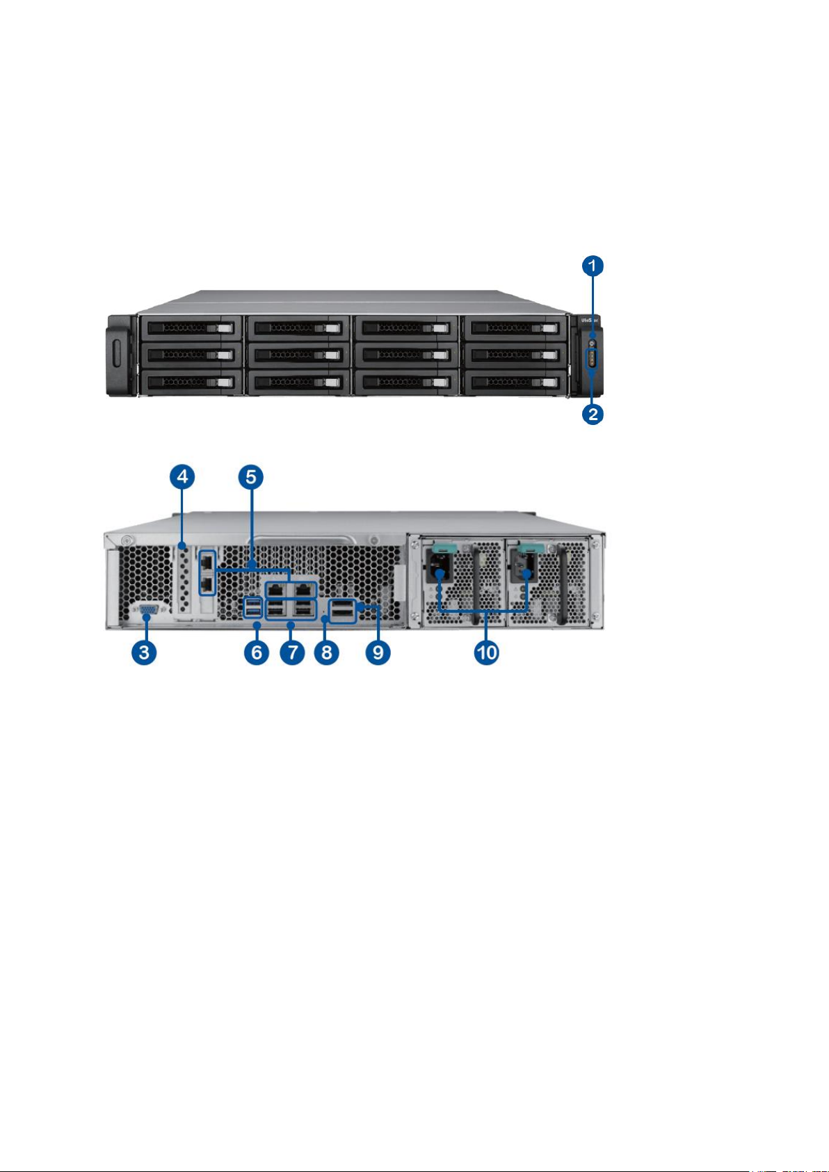
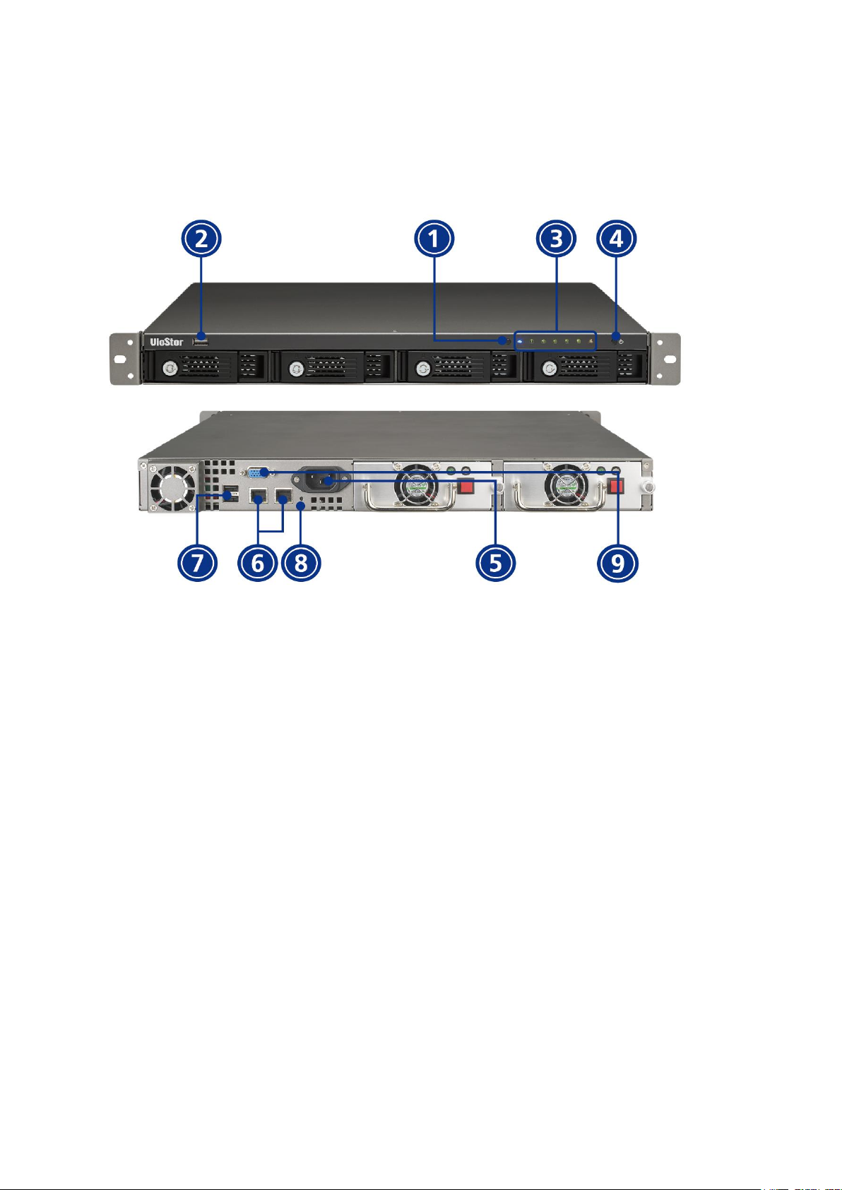
1.2.1 VS-12164U-RP Pro/VS-12156U-RP Pro/VS-12148U-RP Pro/VS-12140
U-RP Pro
1. Power button
2. LED indicators: 10 GbE, Status, LAN, eSATA Select button
3. VGA
4. Expansion slot x 1 (reserved)
5. Gigabit LAN x 4
6. USB 3.0 x 2
7. USB 2.0 x 4
8. Password & network settings reset button
9. eSATA x 2 (reserved)
10. Power connector x 2
Page 12

12
Page 13
13
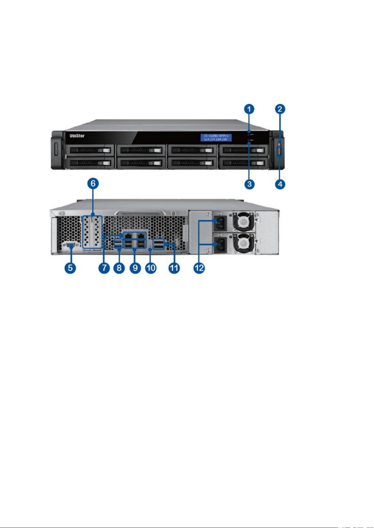
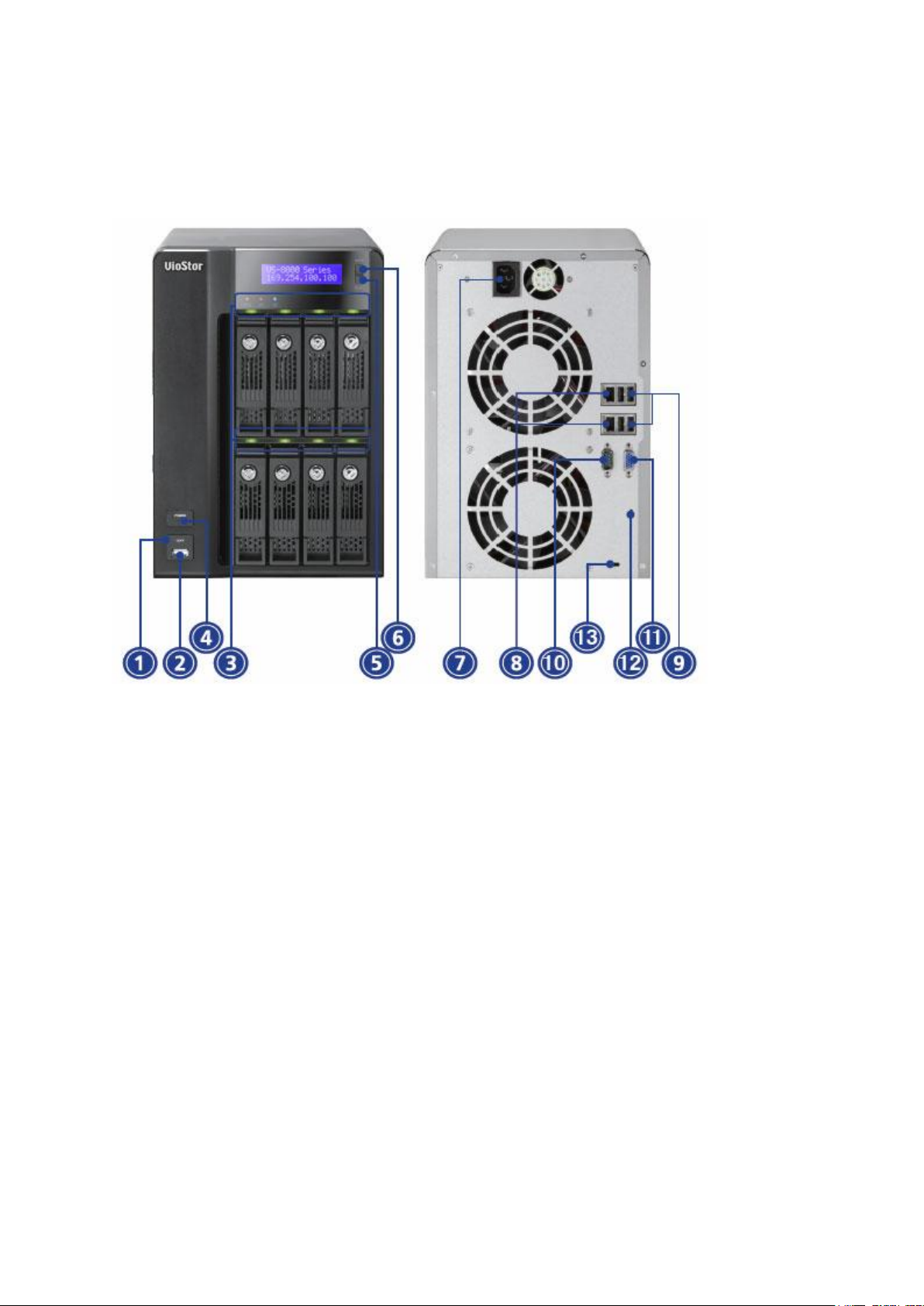
1.2.2 VS-8148U-RP Pro/VS-8140U-RP Pro/VS-8132U-RP Pro/VS-8124U-RP
Pro
1. Enter button
2. Power button
3. Select button
4. LED indicators: 10 GbE, Status, LAN, eSATA
5. VGA
6. Expansion slot x 2 (reserved)
7. Gigabit LAN x 2
8. USB 3.0 x 2
9. USB 2.0 x 4
10. Password & network settings reset button
11. eSATA x 2 (reserved)
12. Power connector x 2
Page 14
14
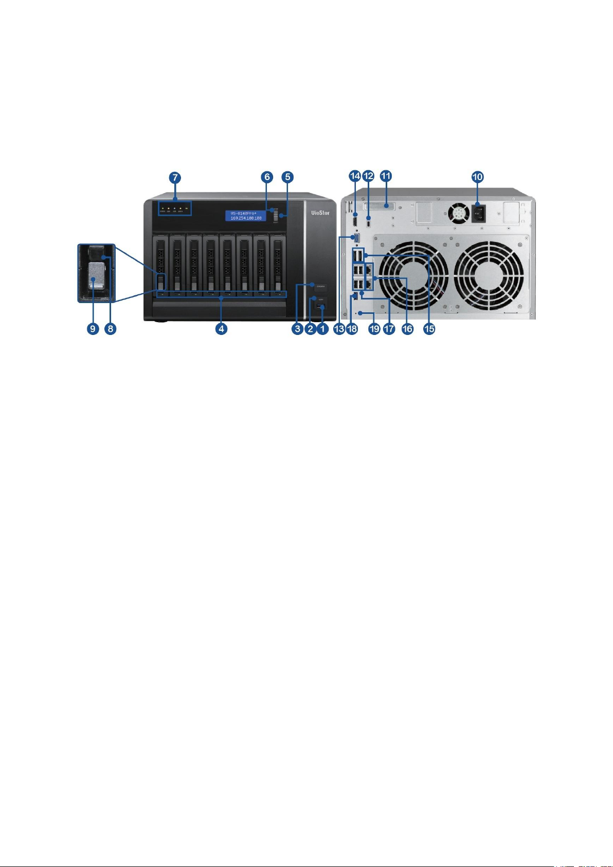
1.2.3 VS-8148 Pro+/VS-8140 Pro+/VS-8132 Pro+/VS-8124 Pro+
1. USB 3.0
2. One-touch-auto-video-backup button
3. Power button
4. Hard drive LEDs
5. Select button
6. Enter button
7. LED indicators: Status, LAN, USB, eSATA, 10 GbE
8. Tray lock
9. Release button
10. Power connector
11. Expansion slot
12. Kensington security slot
13. VGA
14. HDMI
15. eSATA x 2 (reserved)
16. Gigabit LAN x 2
17. USB 2.0 x 4
18. USB 3.0
19. Password & network settings reset button
Page 15
15
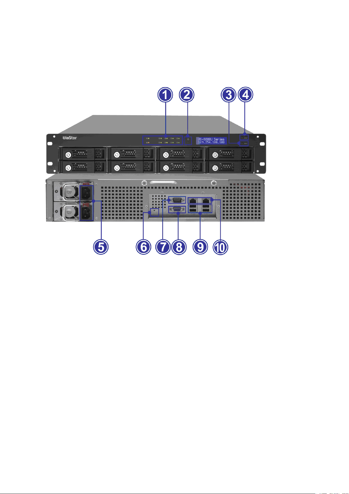
1.2.4 VS-8040U-RP/VS-8032U-RP/VS-8024U-RP
1. LED indicators: Status, LAN, USB, HDD1–8
2. Power button
3. Select button
4. Enter button
5. Power connector
6. Password & network settings reset button
7. RS-232 port
8. VGA
9. USB 2.0 x 4
10. Gigabit LAN x 2
Page 16
16
1.2.5 VS-8040/VS-8032/VS-8024
1. One-touch-auto-video-backup button
2. USB 2.0
3. LED indicators: Status, LAN, USB, HDD1–8
4. Power button
5. Select button
6. Enter button
7. Power connector
8. Gigabit LAN x 2
9. USB 2.0 x 4
10. RS-232 port
11. VGA
12. Password & network settings reset button
13. Kensington security slot
Page 17
17
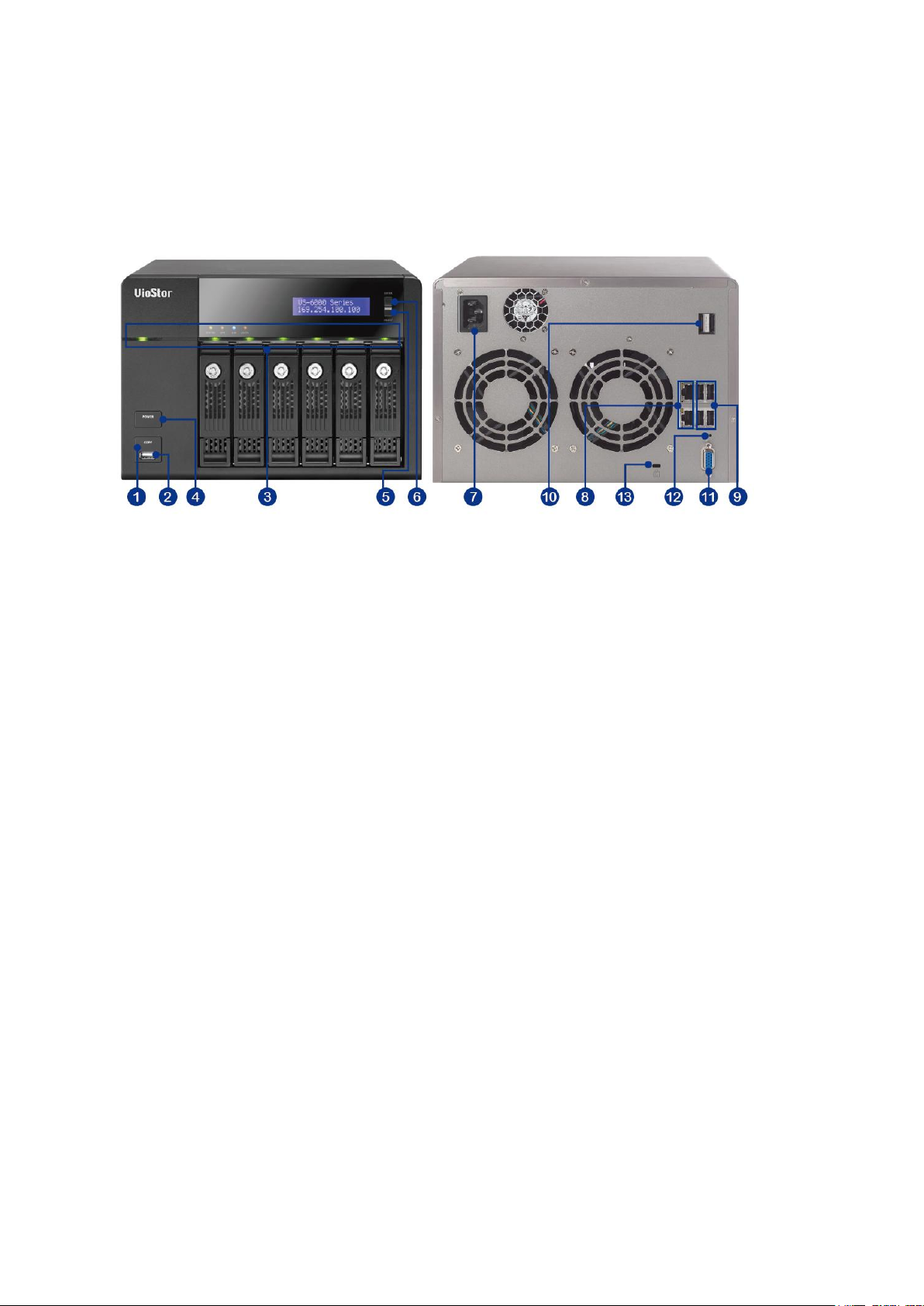
1.2.6 VS-6020 Pro/VS-6016 Pro/VS-6012 Pro
1. One-touch-auto-video-backup button
2. USB 2.0
3. LED indicators: Status, LAN, USB, eSATA, HDD1–6
4. Power button
5. Select button
6. Enter button
7. Power connector
8. Gigabit LAN x 2
9. USB 2.0 x 4
10. eSATA x 2 (reserved)
11. VGA
12. Password & network settings reset button
13. Kensington security slot
Page 18
18
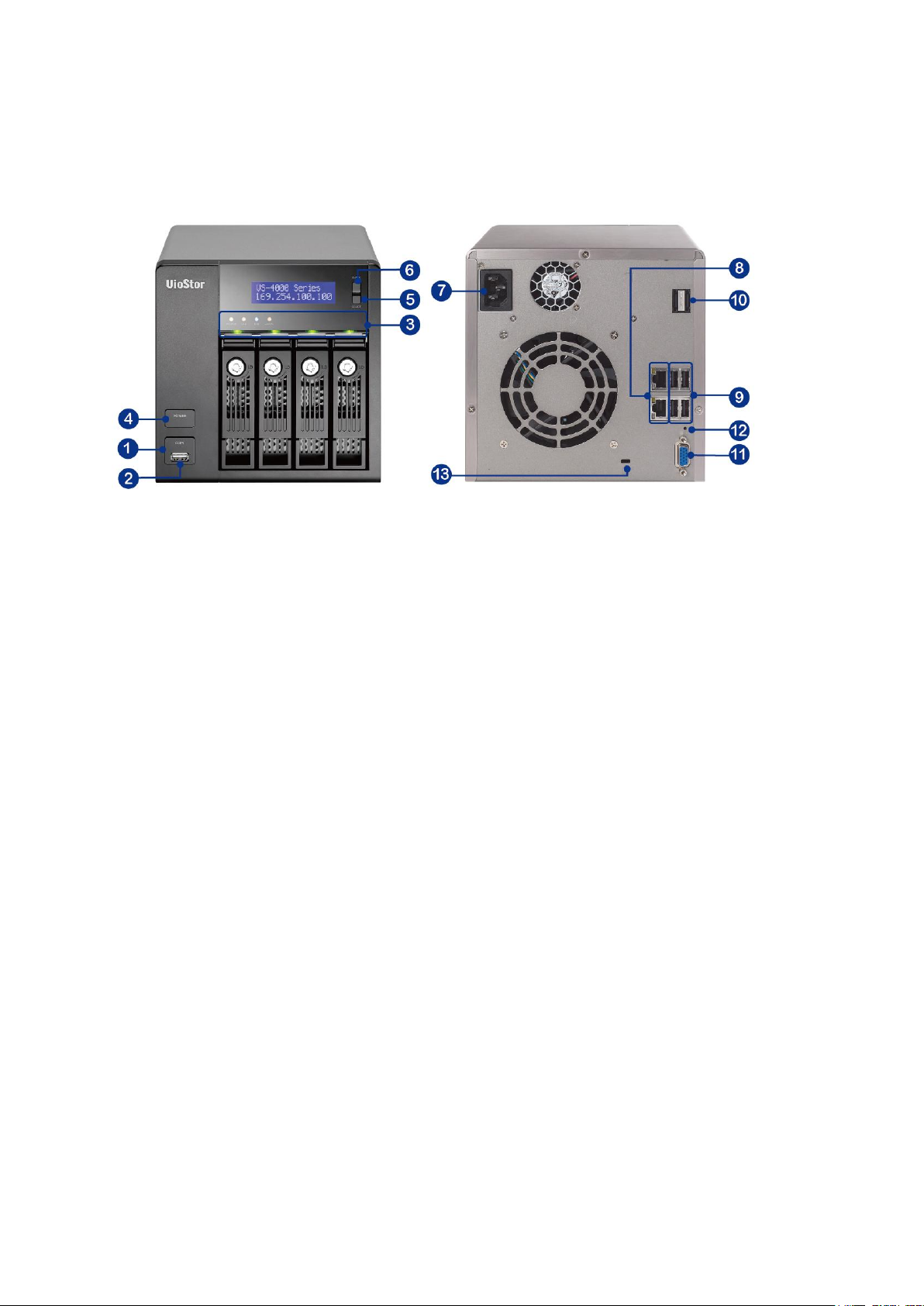
1.2.7 VS-4016U-RP Pro/VS-4012U-RP Pro/VS-4008U-RP Pro
1. One-touch-auto-video-backup button
2. USB 2.0
3. LED indicators: Status, LAN, USB, eSATA, HDD1–4
4. Power button
5. Power connector
6. Gigabit LAN x 2
7. USB 2.0 x 4
8. eSATA x 2 (reserved)
9. VGA
10. Password & network settings reset button
Page 19
19
1.2.8 VS-4016 Pro/VS-4012 Pro/VS-4008 Pro
1. One-touch-auto-video-backup button
2. USB 2.0
3. LED indicators: Status, LAN, USB, eSATA, HDD1–4
4. Power button
5. Select button
6. Enter button
7. Power connector
8. Gigabit LAN x 2
9. USB 2.0 x 4
10. eSATA x 2 (reserved)
11. VGA
12. Password & network settings reset button
13. Kensington security slot
Page 20
20
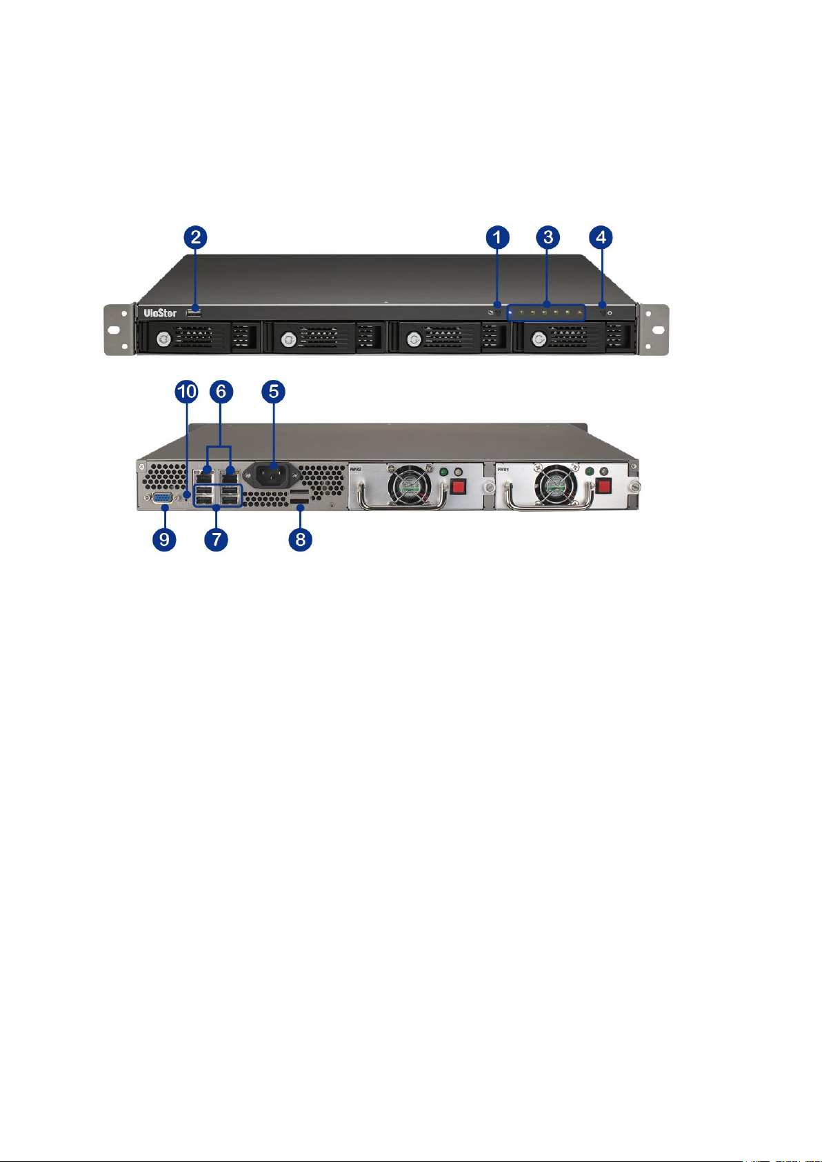
1.2.9 VS-4016U-RP
1. One-touch-auto-video-backup button
2. USB 2.0
3. LED indicators: USB, Status, HDD1–4, LAN
4. Power button
5. Power connector
6. Gigabit LAN x 2
7. USB 2.0 x 2
8. Password & network settings reset button
9. VGA
Page 21
21
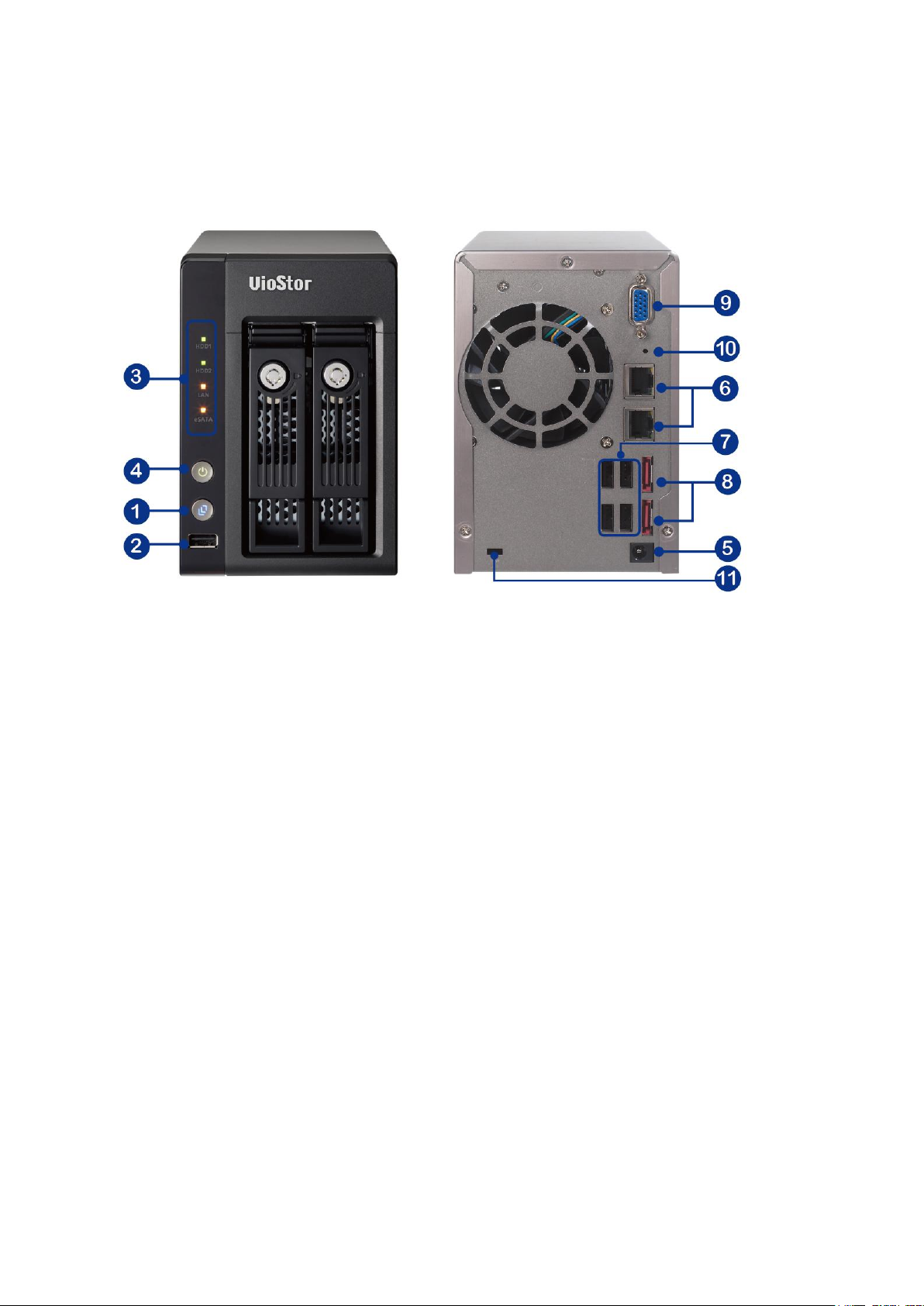
1.2.10 VS-2012 Pro/VS-2008 Pro/VS-2004 Pro
1. One-touch-auto-video-backup button
2. USB 2.0
3. LED indicators: HDD1, HDD2, LAN, eSATA
4. Power button
5. Power connector
6. Gigabit LAN x 2
7. USB 2.0 x 2
8. eSATA x 2 (reserved)
9. VGA
10. Password & network settings reset button
11. Kensington security slot
Page 22
22
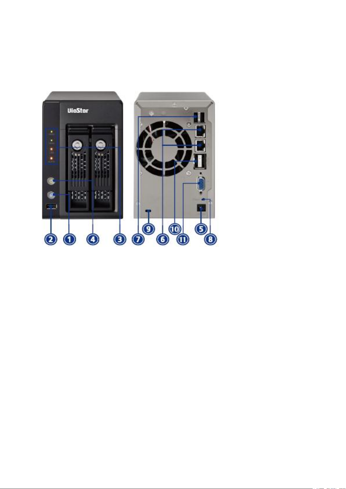
1.2.11 VS-2012/VS-2008
1. One-touch-auto-video-backup button
2. USB 2.0
3. LED indicators: HDD1, HDD2, LAN, eSATA
4. Power button
5. Power connector
6. Gigabit LAN x 2
7. USB 2.0 x 2
8. Password & network settings reset button
9. Kensington security slot
10. eSATA x 2 (reserved)
11. VGA (reserved)
Page 23
23
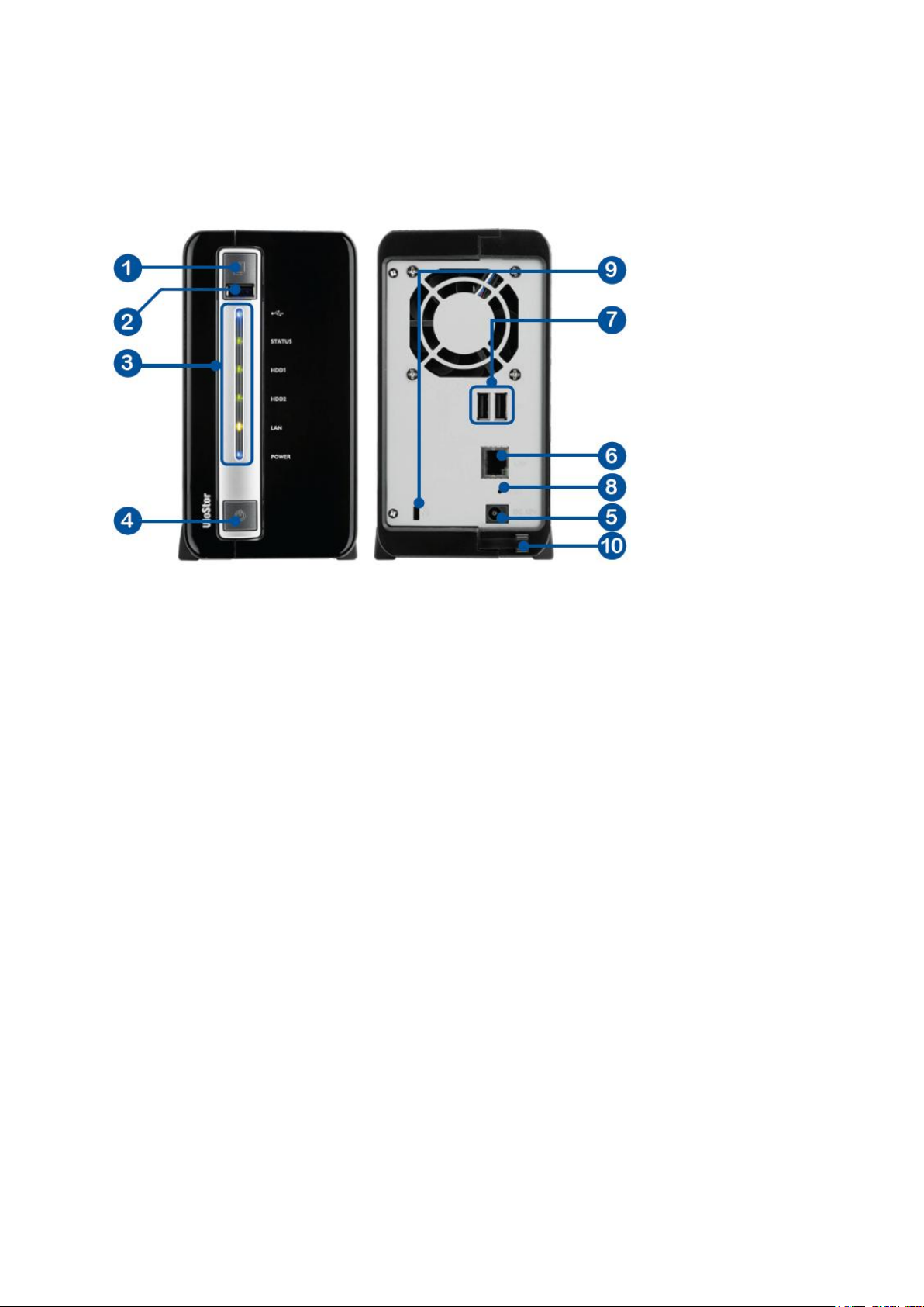
1.2.12 VS-2004L/VS-2008L
1. One-touch-auto-video-backup button
2. USB 2.0
3. LED Indicators: USB, status, HDD1, HDD2, LAN, power
4. Power button
5. Power connector
6. Gigabit LAN
7. USB 2.0 x 2
8. Password & network settings reset button
9. K-Lock security slot
10. Power cord hook
Page 24
24
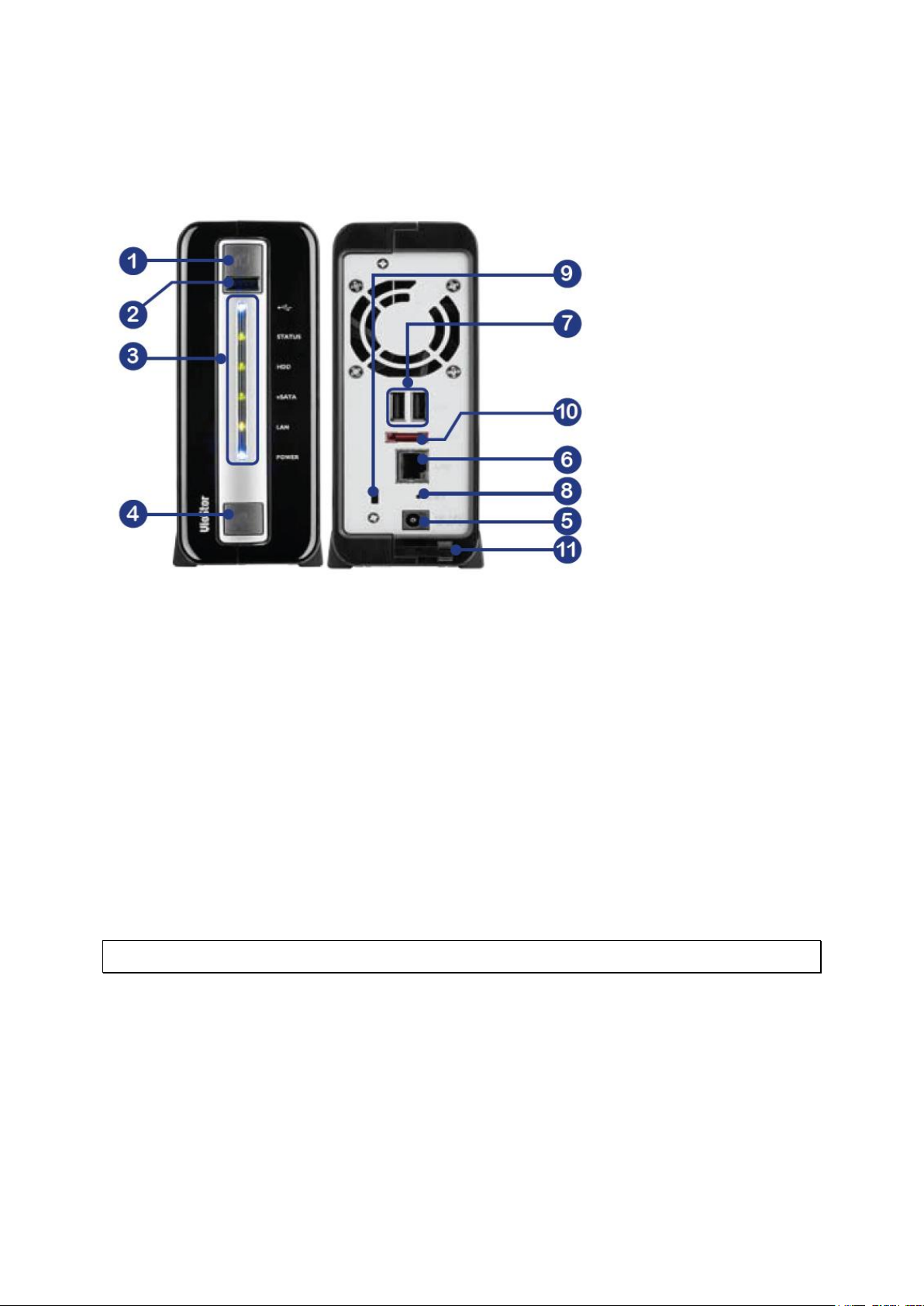
1.2.13 VS-1004L
1. One-touch-auto-video-backup button
2. USB 2.0
3. LED Indicators: USB, status, HDD, eSATA, LAN, power
4. Power button
5. Power connector
6. Gigabit LAN
7. USB 2.0 x 2
8. Password & network settings reset button
9. K-Lock security slot
10. eSATA
11. Power cord hook
Note: This model is designed for some projects only.
Page 25

25
Chapter 2. Install the NVR
For the information of hardware installation, see the ‘Quick Installation Guide’ (QIG) in the
product package. The QIG can also be found in the product CD-ROM or QNAP website
(http://www.qnapsecurity.com).
Page 26

26
No. of
Channels
Format
CPU
Others
4
M-JPEG
Intel Pentium 4 CPU,
2.4GHz or above
Operation system:
Microsoft Windows
7, Vista, XP
Memory: 2GB or
above
Network port:
100Mbps Ethernet
port or above
Web browser:
Microsoft Internet
Explorer 6.0 or
above
CD-ROM drive
Recommended
resolution: 1024 x
768 pixels or above
MPEG-4/MxPEG/H.264
Dual core CPU, 2.0GHz
or above
8
M-JPEG
Intel Pentium 4 CPU,
2.8GHz or above
MPEG-4/MxPEG/H.264
Dual core CPU, 2.4GHz
or above
12
M-JPEG
Intel Pentium 4 CPU,
3.0GHz or above
MPEG-4/MxPEG/H.264
Dual core CPU, 2.8GHz
or above
16
M-JPEG
Dual core CPU, 2.4GHz
or above
MPEG-4/MxPEG/H.264
Quad core CPU,
2.33GHz or above
20
M-JPEG
Dual core CPU, 2.6GHz
or above
MPEG-4/MxPEG/H.264
Quad core CPU, 2.6GHz
or above
40
M-JPEG
Quad core CPU 2.33GHz
or above
MPEG-4/MxPEG/H.264
Core i7 CPU 2.8GHz or
above
48
M-JPEG
Quad core CPU 3.0GHz
or above
MPEG-4/MxPEG/H.264
Core i7 CPU 3.4GHz or
above
2.1 Personal Computer Requirements
For better system performance, the computer should at least fulfill the following
requirements:
Page 27
27
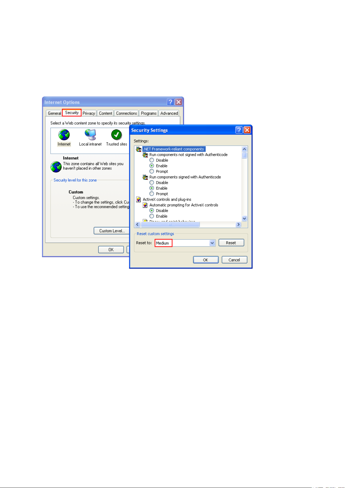
Security Settings of the Web Browser
Please make sure the security level of the IE browser in Internet Options is set to Medium
or lower.
Page 28
28
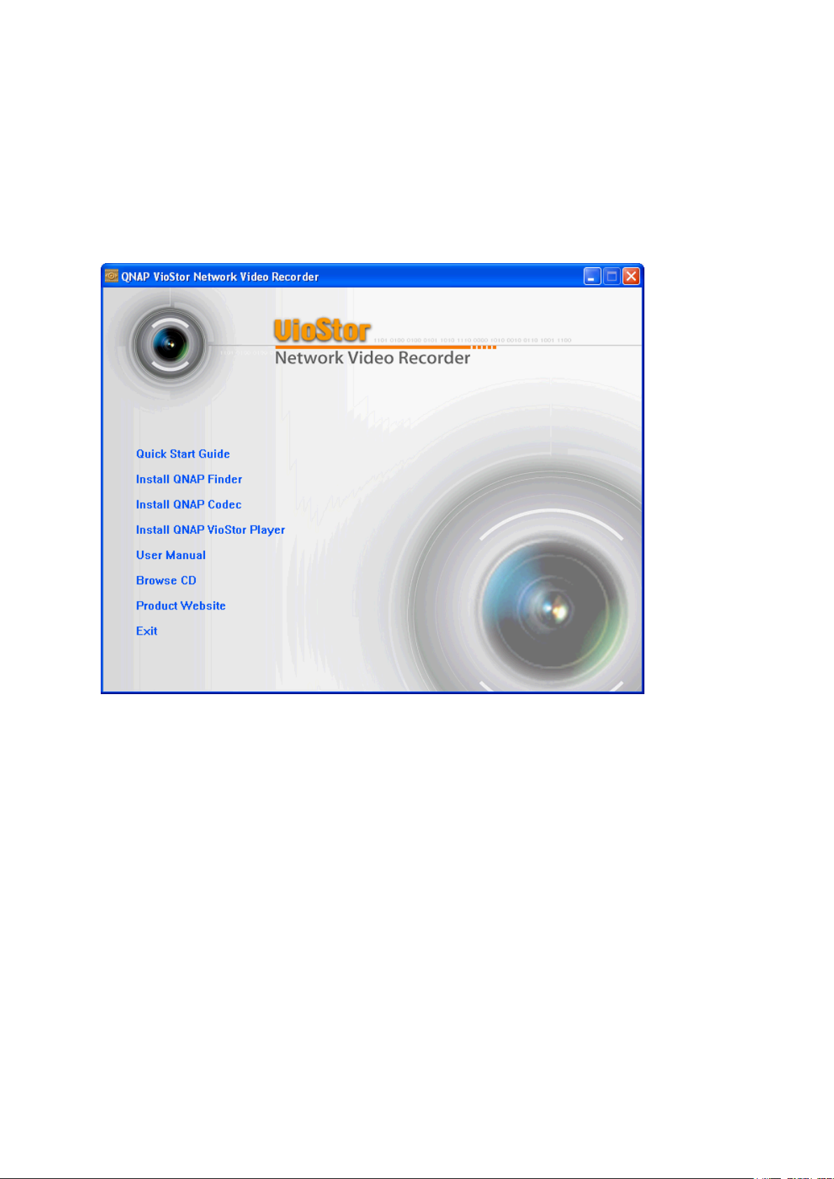
2.2 Browse CD-ROM
Run the product CD-ROM on a Windows PC to access the Quick Start Guide and user manual,
and install codec and software utilities Finder and VioStor Player.
Page 29
29
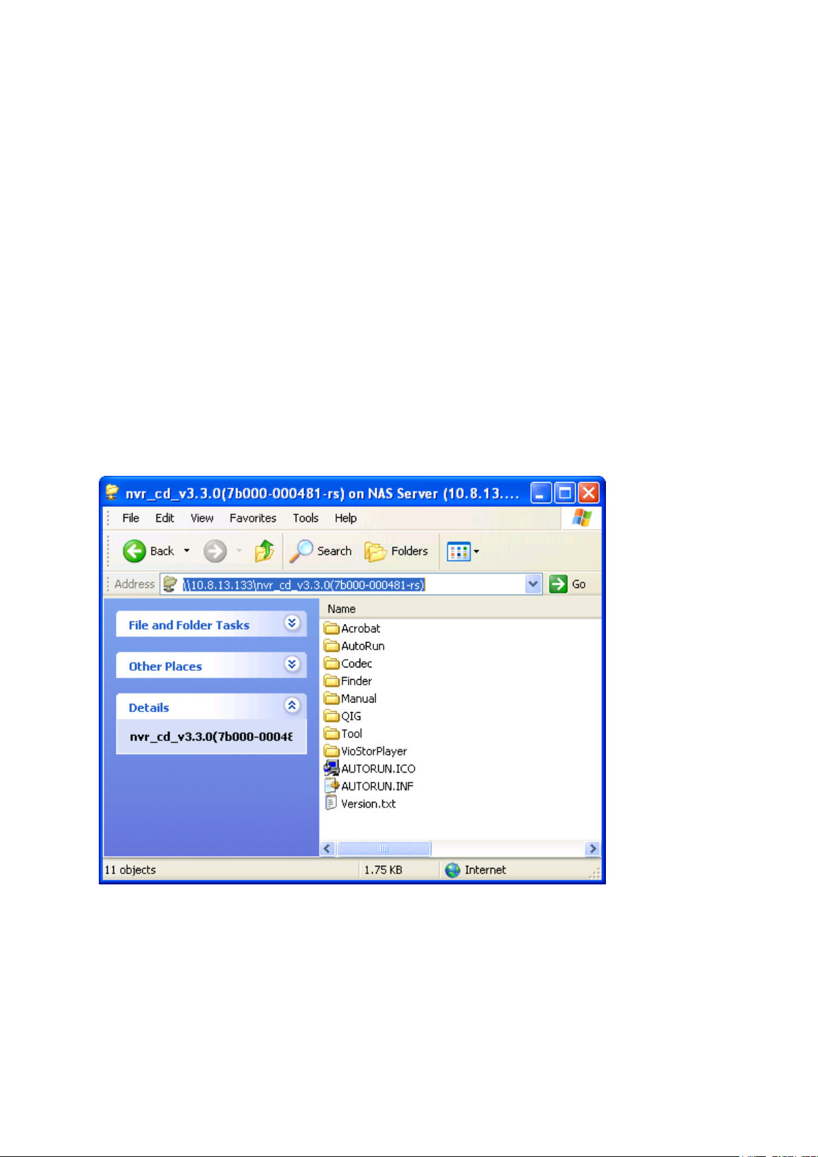
Browse the CD-ROM and access the following contents:
Finder: The setup program of QNAP Finder. This tool is used to discover the NVR
servers available on the local network and configure the network settings of the NVR.
Manual: The user manuals of the NVR.
QIG: View the hardware installation instructions of the NVR.
Codec: The codec for playing AVI videos recorded by the NVR via Windows Media
Player.
Tool: This folder contains IPP library and monitor plugin. If you failed to install the
ActiveX plugin when connecting to the monitoring page of the NVR by an IE browser,
install the plugin from the CD-ROM.
VioStorPlayer: The setup program of VioStor Player, a tool to play the videos recorded
by the NVR. If you failed to install VioStor Player when connecting to the playback
page of the NVR by an IE browser, install the plugin from the CD-ROM.
Page 30

30
2.3 Hard Disk Drives Compatibility List
This product works with 2.5-inch and 3.5-inch SATA hard disk drives from popular hard disk
brands. For the hard disk compatibility list, please visit
http://www.qnapsecurity.com/pro_compatibility.asp
QNAP disclaims any responsibility for product damage/malfunction or data
loss/recovery due to misuse or improper installation of hard disks in any occasions for any
reasons.
2.4 IP Cameras Compatibility List
For the information of supported IP camera models, please visit
http://www.qnapsecurity.com/pro_compatibility_camera.asp
Page 31

31
LED
Color
LED Status
Description
System
Status
Red/
Green
Flashes green
and red
alternately
every 0.5 sec
1) A hard drive on the NVR is being formatted
2) The NVR is being initialized
3) The system firmware is being updated
4) RAID rebuilding is in process
5) Online RAID Capacity Expansion is in
process
6) Online RAID Level Migration is in process
Red
1) A hard drive is invalid
2) The disk volume has reached its full
capacity
3) The disk volume is going to be full
4) The system fan is out of function
5) An error occurs when accessing
(read/write) the disk data
6) A bad sector is detected on the hard drive
7) The NVR is in degraded read-only mode (2
member drives fail in a RAID 5 or RAID 6
configuration, the disk data can still be
read)
8) (Hardware self-test error)
Flashes red
every 0.5 sec
The NVR is in degraded mode (one member
drive fails in RAID 1, RAID 5 or RAID 6
configuration)
Flashes green
every 0.5 sec
1) The NVR is starting up
2) The NVR is not configured
3) A hard drive is not formatted
Green
The NVR is ready
Off
All the hard drives on the NVR are in standby
mode
LAN
Orange
Orange
The NVR is connected to the network
Flashes
orange
The NVR is being accessed from the network
10 GbE*
Green
(Reserved)
HDD (Hard
Drive)
Red/
Green
Flashes red
The hard drive data is being accessed and a
read/write error occurs during the process
2.5 Check System Status
LED Display & System Status Overview
Page 32

32
Red
A hard drive read/write error occurs
Flashes green
The hard drive data is being accessed
Green
The hard drive can be accessed
USB
Blue
Flashes blue
every 0.5 sec
1) A USB device is detected
2) A USB device is being removed from the
NVR
3) The USB device connected to the front
USB port of the NVR is being accessed
4) The NVR data is being copied to the
external USB device
Blue
The USB device connected to the front USB
port of the NVR is ready
Off
1) No USB is detected
2) The NVR has finished copying the data to
the USB device connected to the front USB
port of the NVR
eSATA†
Orange
Flashes
The eSATA device is being accessed
*The 10 GbE network expansion function is reserved.
† The eSATA port is available on certain models only. Please refer to
http://www.qnapsecurity.com for more information.
Page 33

33
Beep sound
No. of Times
Description
Short beep (0.5 sec)
1
1) The NVR is starting up
2) The NVR is being shut down (software
shutdown)
3) The reset button is pressed
4) The system firmware has been updated
Short beep (0.5 sec)
3
The NVR data cannot be copied to the external
device by pressing the
one-touch-auto-video-backup button.
Short beep (0.5 sec),
long beep (1.5 sec)
3, every 5 min
The system fan is out of function
Long beep (1.5 sec)
2
1) The disk volume is going to be full
2) The disk volume has reached its full
capacity
3) The hard drives on the NVR are in degraded
mode
4) Hard disk rebuilding process starts
1
1) The NVR is turned off by force shutdown
(hardware shutdown)
2) The NVR has been turned on successfully
and is ready
Beep Alarm (beep alarm can be disabled in ‘System Tools’ > ‘Hardware Settings’)
Page 34

34
2.6 System Configuration
Install Finder
1. Run the product CD, the following menu is shown. Click ‘Install Finder’.
2. Follow the instructions to install the Finder. Upon successful installation, run the
Finder. If the Finder is blocked by the firewall, unblock it.
3. The Finder detects the NVR servers on the local network. If the server has not been
initialized, you will be prompted to perform quick setup. Click ‘Yes’ to continue.
Note: If the NVR is not found, click ‘Refresh’ to try again.
Page 35

35
Use name: admin
Password: admin
4. Enter the administrator name and password to perform quick setup. The default
administrator name and password are as below:
Note: Make sure all the IP cameras are configured and connected to the network.
5. The quick configuration page will be shown. Click ‘Continue’ and follow the
instructions to finish the configuration. For further information, please refer to
Chapter 6.1.
Page 36

36
6. Click ‘Start installation’ to execute the quick configuration.
7. After the quick configuration, the NVR is ready for use. Click ‘Start Monitoring’ to
view the live video from the IP cameras or click ‘Close’ to return to the home page of
the system administration.
Page 37

37
8. The first time to connect to the monitoring page of the NVR, install the ActiveX add-on.
The live video from the IP cameras configured on the NVR and the recording status of
each channel are shown.
Page 38

38
Chapter 3. Use the NVR by Local Display
Note: This feature is supported by the VioStor Pro Series NVR only. The models include
VS-12164U-RP Pro, VS-12156U-RP Pro, VS-12148U-RP Pro, VS-12140U-RP
Pro,VS-8148U-RP Pro, VS-8140U-RP Pro, VS-8132U-RP Pro, VS-8124U-RP Pro, VS-8148
Pro+, VS-8140 Pro+, VS-8132 Pro+, VS-8124 Pro+, VS-8040U-RP, VS-8032U-RP,
VS-8024U-RP, VS-8040, VS-8032, VS-8024, VS-6020 Pro, VS-6016 Pro, VS-6012 Pro,
VS-4016U-RP Pro, VS-4012U-RP Pro, VS-4008U-RP Pro, VS-4016 Pro, VS-4012 Pro,
VS-4008 Pro, VS-2012 Pro, VS-2008 Pro, and VS-2004 Pro.
Connect a monitor or TV to the NVR via the HDMI or VGA interface to perform PC-less quick
configuration, monitoring, and video playback. To use this feature, follow the steps
below:
1. Make sure at least one hard drive has been installed on the NVR.
2. Connect the NVR to the network.
3. Make sure the IP cameras have been configured and connected to the network.
4. Connect an HDMI or a VGA monitor or TV (suggested video output resolution: 1920 x
1080)* to the HDMI or VGA interface of the NVR.
5. Connect a USB mouse and a USB keyboard (optional) to the USB ports of the NVR.
6. Turn on the NVR.
*The local display feature supports maximum screen resolution of 2048*1536 (QXGA).
Page 39

39
Default user name: admin
Password: admin
When the NVR is turned on, the login screen will be shown. Select the language. Enter
the administrator name and password. If the NVR has not been configured, skip the login
page and enter Quick Configuration (refer to Chapter 3.1).
Click the keyboard icon to enter the necessary information if a USB keyboard is not
available.
The monitoring page will be shown upon successful login, refer to Chapter 3.3 for details.
Page 40

40
3.1 Quick Configuration
If the NVR has not been configured, Quick Configuration Wizard will be shown. Follow the
instructions of the wizard to complete the system setup.
Note: All the changes will be effective only after applying the settings in the last step.
1. The system information will be shown. Select the language and click ‘Next’.
Page 41

41
2. Change the admin password or use the default password (admin).
3. Select to obtain the network settings automatically or enter the network settings.
Page 42

42
4. Enter the date and time settings. Select to synchronize the server time with an
Internet time server. To enter a domain name for the NTP server, make sure the DNS
server has been correctly set up.
5. Select the disk configuration. Click ‘Disk Information’ to view the hard disk drive
details. Note that all the disk data will be deleted when the disk volume is initialized.
Page 43

43
6. Configure the IP camera settings. If no IP cameras have been set, try to search for the
cameras on the local network.
a. The cameras found will be shown. Select the IP cameras and click ‘Add’ to add the
channels.
Page 44

44
b. To manually add an IP camera or edit the camera settings, click .
c. Enter the camera settings. Click ‘Test’ to test the connection. Click ‘Remove’ to
delete the camera.
Page 45

45
d. To edit the recording settings, click next to ‘Recording Settings’. Define the
recording settings and click ‘OK’.
Digital Watermarking: Enable this option to add digital watermarks to the video files
recorded to the NVR. Use the Watermark Proof utility to verify if the video files were
maliciously modified. For more information, refer to Chapter 5.2.
Page 46

46
7. Verify the settings and click ‘Next’ to initialize the server.
8. After the system has been initialized, the NVR is ready for use. Click ‘Start Monitoring’
to enter the monitoring screen.
Page 47

47
3.2 System Configuration
To manage the system settings such as administrator password, network and time settings,
click on the monitoring screen. Note that this button (option) will be shown for
administrator access only.
Select the language and click the icons to configure the settings.
Page 48

48
Icon
Description
Perform quick configuration of the system.
Change the administrator password to login local display.
Change the network settings.
Change the date and time settings.
Configure the disk volume and initialize the hard disks.
Configure the IP camera settings.
Page 49

49
View video
image and
IP camera
info
Camera
list
Select monitoring mode
PTZ camera control panel
3.3 Monitoring
Upon successful login, the monitoring screen will be shown. Monitor the IP cameras,
change the display mode, enable or disable manual recording, control the PTZ cameras,
and so on.
Page 50

50
Icon
Description
Monitor:
Enter the monitoring page.
Playback:
Enter the playback page.
Configuration:
Enter the system configuration page; allows admin access
only.
Options:
Configure the event notification settings, video window display
settings, screen resolution, etc.
Hide left panel:
Hide the panel on the left of the monitoring page.
Show left panel:
Show the panel on the left of the monitoring page.
Logout:
Logout the NVR.
About:
View the server name, NVR model, and firmware version.
Manual recording:
Enable or disable recording on the IP camera. The
administrator can select to enable or disable this function in
‘Camera Settings’ > ‘Recording Settings’ on the web-based
administration interface.
Audio (optional):
Turn on or off the audio support for the monitoring page.
Page 51

51
Event notification:
When the alarm recording is enabled and an event is detected,
this icon will be shown. Click this icon to view the alert details.
The alert sound can be turned on or off. To clear all the logs,
click ‘Clear All’.
Page 52

52
Icon
Description
Pan and tilt:
If the PTZ camera supports pan and tilt functions, click these
buttons to pan or tilt the camera.
Preset positions:
Select the preset positions of the PTZ camera.
Zoom in/Zoom out:
If the PTZ camera supports zooming, click these buttons to
zoom in or zoom out.
Digital zoom:
Select a channel and click this button to enable the digital zoom
function. When enabled, click ‘+’ to zoom in or ‘-’ to zoom out.
Focus control:
Adjust the focus control of the PTZ camera.
PTZ Control Panel
The term ‘PTZ’ stands for ‘Pan/Tilt/Zoom’. If the IP camera supports PTZ, use the control
panel on the NVR to adjust the viewing angel of the IP camera. These functions are
available depending on the camera models. Please consult the camera's documentation
for details. Note that the digital zoom function will be disabled when the PTZ function is in
use.
Page 53

53
Icon
Description
Full screen
Single-channel mode
4-channel mode
6-channel mode
8-channel mode
9-channel mode
10-channel mode
12-channel mode
Select the display page number
Sequential mode. This mode can be used with other display modes. Click
to enable or disable sequential mode. Click to define the time
interval of which the channels will be displayed.
Display Mode
The NVR supports various display modes for monitoring. Click the correct icon to switch
the display mode.
Note:
VS-2004 Pro supports 1 to 6-channel display modes only.
VS-2008 Pro, VS-4008 Pro, VS-4008U-RP Pro support 1 to 10-channel display modes only.
Other NVR models support 1 to 12-channel display modes.
Page 54

54
Live View Screen
Upon successful configuration of the IP cameras, enter the monitoring screen to view the
live video from the cameras.
If the camera supports pan and tilt functions, click the channel on the screen and adjust the
viewing angle with a mouse. If zooming is supported, scroll the mouse wheel to zoom in
or zoom out the video. These functions are available depending on the camera models.
Please consult the camera's documentation for details.
Page 55

55
Icon
Camera Status
Scheduled or continuous recording is in process
This IP camera supports audio function
This IP camera supports PTZ function
Manual recording is enabled
The recording triggered by advanced event management (‘Camera Settings’ >
‘Alarm Settings’ > ‘Advanced Mode’) is in process
The alarm input 1 of the IP camera is triggered
The alarm input 2 of the IP camera is triggered
The alarm input 3 of the IP camera is triggered
Motion detection recording is in process
Digital zoom is enabled
Camera Status
The camera status is indicated by the icons shown below:
Page 56

56
Message
Description
Connecting
If the IP camera is located on remote network or the Internet, it may
take some time to establish the connection to the camera.
Disconnected
The NVR cannot connect to the IP camera. Please check the network
connection of the computer and the availability of the IP camera. If the
IP camera is installed on the Internet, open the port on the router or
gateway to connect to the IP camera. Please refer to Appendix B.
No Permission
No access right to view the channel. Please login as a user with the
access right or contact the system administrator.
Server Error
Check the camera settings or update the firmware of the IP camera (if
any). Contact the technical support if the error persists.
Connection Message
When the NVR fails to display the video of an IP camera, a message will be shown in the
channel window to indicate the status.
Note:
1. Enabling or disabling manual recording will not affect scheduled or alarm recording
tasks. They are independent processes.
2. Right click the IP camera channel and select the following options:
a. Full screen
b. Keep aspect ratio
c. Deinterlace (available on particular camera models only)
d. Keep original size
Page 57

57
Options
To configure advanced monitor settings, click .
The following options are provided under the ‘General’ tab.
Event Notification: When this option is enabled and an event is triggered, the alert icon
will be shown on the monitoring channel instantly. Click the icon to view the alert
details.
Display Order: Click ‘Reset’ to reprioritize the monitoring channels to default order.
Page 58

58
The following options are provided under the ‘Video’ tab.
Highlight the video window when an event is triggered: The video window will flash if an
event is triggered.
Display unauthorized channels: Select this option to show the channels that the user
does not have access right to monitor.
Display unconfigured channels: Select this option to show the channels that have not
been configured.
Page 59

59
The NVR detects the resolution settings supported by the connected monitor and selects
the most appropriate setting automatically. To change the screen resolution, click
‘Settings’ under the ‘Screen’ tab. After configuring the resolution settings, the monitoring
screen will be shown.
If the monitor model cannot be detected, the NVR will provide the options 1400*1050,
1280*1024, 1024*768.
Page 60

60
3.4 Video Playback
The videos on the NVR can be played by the local display. To use this feature, click on
the monitoring screen. Most of the icons on the playback screen are the same as those on
the monitoring screen. Please refer to Chapter 3.2 for the icon description.
Note: The playback access right to the IP cameras is required to play the videos. Login
the NVR as admin and edit the playback access right in ‘User Management’ by the
web-based administration interface.
When the playback screen is shown, select a camera channel on the NVR. Next, select the
start and end time of the video, click to start searching. The videos which match
the search criteria will be played automatically.
Note: The maximum time interval between the start and end time is 3 days.
Page 61

61
Playback Settings:
Play, pause, stop, reverse play a video file, or select to play the previous or next file.
When playing a video, use the scroll bar to adjust the playback speed or click the digital
zoom icon to zoom in or zoom out the video. Right click the IP camera channel and
select the following options:
a. Full screen
b. Keep aspect ratio
c. Deinterlace (available on particular camera models only)
d. Keep original size
Page 62

62
3.5 Video Conversion & Export
The NVR supports converting the video files to AVI format and saving the files to an
external USB storage device.
Note:
To use this feature, connect a USB storage device to the front USB port of the NVR and
make sure the device has been correctly formatted.
The access right to play the videos of the IP camera is required to convert the video
files.
Follow the steps below to export the video files of an IP camera from the NVR and convert
the files to an AVI file.
1. Enter the playback interface of the NVR. Click (Convert to AVI file).
Page 63

63
2. Select the IP camera and the recording type.
3. Specify the start and end time of the video files.
4. Enter the file name of the video file.
5. Click ‘OK’ to convert the video files to an AVI file and save them to the external USB
storage device.
Page 64

64
Double click to
login the server
Chapter 4. Use the NVR by Web-based Interface
Use Microsoft Internet Explorer to monitor the IP cameras and manage the functions of the
NVR.
Important Notice:
Before using the NVR, install the hard disks in the server correctly and finish the disk
formatting and configuration. Otherwise, the server will not function properly.
4.1 Connect to the NVR
Follow the steps below to connect to the monitoring page of the NVR.
1. Run the Finder. Double click the name of the NVR, or enter the IP address of the
server in the IE browser to connect to the monitoring page.
Page 65

65
Default user name: admin
Default password: admin
2. Enter the user name and password to login the NVR.
3. To view the live video by Internet Explorer, install the ActiveX add-on.
Page 66

66
View
monitoring
channel and
details
PTZ
control
panel
System firmware
Adjust
display
mode
Server
name
4.2 Monitoring Page
Upon successful login, the monitoring page will be shown. Select the display language.
Start to configure the system settings and use the monitoring and recording functions of
the server.
Page 67

67
Icon
Description
Multi display mode:
The NVR supports multi-display mode. (This function can
only be used when the computer or the host is connected to
multiple monitors.)
Multi-server monitoring:
Up to 128 channels from multiple QNAP NVR servers can be
monitored.
Select language:
Select the display language.
E-map:
Upload E-map(s) and indicate the locations of the IP cameras.
The administrators are allowed to edit and view the E-map.
Other users can only view the E-map.
System configuration:
Login the system administration page (admin access
required).
Monitoring settings:
Configure the advanced settings of the monitoring page.
Specify the source of the video/audio stream, event
notification, and snapshot folder.
Playback:
Enter the video playback page. The administrator can grant
access right to the users to playback the videos.
Help:
View the system online help.
Logout:
Logout the NVR.
Snapshot:
Take a snapshot on the selected channel. When the picture is
shown, right click the picture to save it to the computer.
Manual recording:
Enable or disable manual recording on the selected channel.
The administrator can enable or disable this option on the
system configuration page.
Audio (optional):
Turn on/off the audio support for the monitoring page.
Page 68

68
Login IP camera homepage:
Select a channel and click this button to go to the homepage of
the selected IP camera.
Event notification:
When the alarm recording is enabled and an event is detected,
this icon will be shown. Click this icon to view the alert
details.
Digital zoom:
Select a channel and click this button to enable the digital
zoom function. (This function can also be enabled by right
clicking the monitoring channel.)
Press and hold the left mouse button to zoom in or press and
hold the right mouse button to zoom out. Press the left
mouse button to drag the viewing angle of the IP camera.
Use the mouse wheel or the PTZ control panel to use the digital
zoom function.
Focus control:
Adjust the focus control of the PTZ camera.
Select PTZ camera preset positions:
View the preset positions of the IP camera by clicking the
number buttons. To configure the preset positions of the IP
camera, please refer to the user manual of the IP camera.
Recording storage status:
Display the percentage of the used storage and the free space
of the NVR.
Page 69

69
Note:
1. Enabling or disabling the manual recording feature will not affect the scheduled or
alarm recording.
2. By default, the snapshots are saved in ‘My Documents’ or ‘Documents’> ‘Snapshots’
on Windows.
3. If the snapshot time is inconsistent with the actual time that the snapshot is taken, it
is caused by the network environment but not a system error.
4. Click the event notification icon to view the event details, enable or disable the alert
sound or clear the event logs.
5. When the digital zoom function is enabled on multiple IP cameras, the zooming
function will be affected if the computer performance is not high enough.
Page 70

70
Right click the monitoring channel on the live view page. The following functions are
available depending on the IP camera model.
a. Connect to camera homepage.
b. Camera setting: Enter the configuration page of the IP camera.
c. PTZ: Pan/Tilt/Zoom camera control.
d. Preset: Select the preset positions of the PTZ camera.
e. Enable live tracking: Available on Panasonic NS202(A) camera.
f. Disable live tracking: Available on Panasonic NS202(A) camera.
g. Auto cruising: This feature is used to configure the PTZ cameras to cruise according to
the preset positions and the staying time set for each preset position.
h. Digital zoom: Enable/disable digital zoom.
i. Keep aspect ratio.
Page 71

71
To configure other monitoring options, right click a channel and select ‘Properties’.
Streaming:
Always stream from the server: Select this option to stream the audio and video data
from the NVR. If the computer cannot connect to the IP cameras, select this option to
allow the NVR to stream the data; no extra port forwarding is required. However, the
performance of the NVR may be affected.
Always stream from the network camera: If the NVR and the IP cameras are connected
to the same local network, select this option to stream the video data from the IP
cameras. If the NVR, the IP cameras, and the PC are located behind a router, virtual
server, or firewall, configure port forwarding on the IP cameras to use certain ports.
\
OSD Settings: Specify the font color of the texts on the channels.
Page 72

72
Display Mode:
Fit image to window: Select this option to fit an image to the browser window. Specify
to keep the aspect ratio or not when resizing an image.
Display image in original size: Select this option to display an image in its original size
if it is smaller than the browser window. Specify also how an image will be resized if it
is larger than the browser window.
Shrink image to fit window, maintaining aspect ratio
Shrink image by 1/2, 1/4, 1/8… and so on to fit window
Video Processing: Turn on ‘Deinterlace’ when there are interlaced lines on the video.
Page 73

73
Video Resolution: Specify to adjust the resolution automatically or use a fixed resolution.
To adjust the resolution automatically, the NVR will select the resolution setting* which
best fits the size of the IE browser window. Note that ‘Stream from network camera’ will
not be available if the IP camera does not support streaming from camera or video
resolution configuration. Both options will not be available if the IP camera does not
support multiple streams.
*If an IP camera supports different resolution settings, the NVR will select the smallest
resolution larger than (or equal to) the size of the browser window.
If all the supported resolution settings of an IP camera are smaller than the browser
window, the largest resolution will be selected.
Let me choose other cameras to apply the same settings: Select this option to apply
the changes to other IP cameras. Note that some settings may not be applied if the IP
camera does not support the features, such as streaming from camera or video resolution
configuration.
Page 74

74
Page 75

75
4.2.1 Live Video Window
The live videos of the IP cameras configured on the NVR are shown on the monitoring page.
Click the channel window to use the features supported by the IP camera, e.g. digital zoom
or pan/tilt/zoom.
Page 76

76
Icon
Camera Status
Scheduled or continuous recording is in process
This IP camera supports audio function
This IP camera supports PT function
Manual recording is enabled
The recording triggered by advanced event management (‘Camera
Settings’ > ‘Alarm Settings’ > ‘Advanced Mode’) is in process
The alarm input 1 of the IP camera has been triggered
The alarm input 2 of the IP camera has been triggered
The alarm input 3 of the IP camera has been triggered
A moving object has been detected
Digital zoom is enabled
Message
Description
Connecting
If the IP camera is located on a remote network or the Internet, it may
take some time to establish the connection to the camera.
Disconnected
The NVR cannot connect to the IP camera. Please check the network
connection of the computer and the availability of the IP camera. If the
IP camera is located on the Internet, open the port on the router or
gateway.
No Permission
No access right to view the monitoring channel. Please login as an
authorized user or contact the system administrator.
Server Error
Please check the camera settings or update the firmware of the IP
camera (if any). Contact the technical support if the error persists.
Camera Status
The camera status is indicated by the icons shown below:
Connection Message
When the NVR fails to display the video of an IP camera, a message will be shown in the
channel window to indicate the status.
Page 77

77
Single channel mode
4-channel mode
8-channel mode
10-channel mode
Full screen
Multi-channel mode
9-channel mode
6-channel mode
Picture-in-Picture mode
Sequential mode
Adjust window size
Adjust PT angle
of the camera
Select PTZ camera
preset positions
Zoom out
Focus control of
the PTZ camera
Zoom in
No zooming
Digital zoom
4.2.2 Display Mode
The NVR supports different display modes for viewing the monitoring channels.
4.2.3 PTZ Camera Control Panel
The term ‘PTZ’ stands for ‘Pan/Tilt/Zoom’. If an IP camera supports the PTZ feature, use
the control panel on the NVR to adjust the viewing angel of the IP camera. These functions
are available depending on the camera models. Please refer to the user manual of the IP
cameras for more information. Note that the digital zoom function will be disabled when
the PTZ function is in use.
Page 78

78
4.2.4 Multi-server Monitoring
Follow the steps below to use the multi-server monitoring feature of the NVR.
1. Click ‘Server List’ on the monitoring page.
a. Click ‘Auto Detect’ to search for the NVR on the LAN and add the server to the server
list.
b. Click ‘Add’ to add the NVR to the server list.
2. Up to 128 channels from multiple NVR servers can be added for monitoring.
Page 79

79
4.2.5 Monitor Settings
To configure advanced monitor settings, click .
The following options are provided under the ‘General’ tab.
Event Notification: When this option is enabled and an event is triggered, the alert icon
will be shown on the monitoring channel instantly. Click the icon to view the alert
details.
Display Order: Click ‘Reset’ to reprioritize the monitoring channels to the default order.
Browser: Select to show or hide the toolbars of the IE browser.
Page 80

80
The following options are provided under the ‘Video’ tab.
Video Streaming
Stream from the server: If the IP camera cannot be connected from the computer,
select this option and the video will be streamed from the NVR. This option does not
require extra port mapping configuration; but may influence the performance of the
NVR.
Stream from IP camera: If the NVR and the IP cameras are located on the same LAN,
select this option to stream the video from the IP camera. Note that the port
forwarding settings on the IP cameras must be configured if the NVR, IP cameras, and
the computer are located behind a router, a virtual server, or a firewall.
Video Windows
Highlight the video window when an event is triggered: The video window will flash if an
event is triggered.
Display unauthorized channels: Select this option to show the channels that the user
does not have the access right to monitor.
Display unconfigured channels: Select this option to show the channels that have not
been configured.
Decoder
Select this option to multithread decode H.264 video streams when 1 or 4-channel view is
in use.
Page 81

81 82
Page 82

The following options are provided under the ‘Snapshot’ tab.
Snapshot: Specify the location where the snapshots are saved and the image format
(JPEG or BMP).
Show timestamp and camera name: Show the timestamp and the camera name on the
snapshot.
Save the snapshot as it is displayed: Select this option to save the snapshot as it is
displayed on the window. Otherwise, the snapshot will be saved in its original size.
Page 83

83
4.2.6 Auto Cruising
The auto cruising feature of the NVR is used to configure the PTZ cameras to cruise
according to the preset positions and the staying time set for each preset position.
To use the auto cruising feature, follow the steps below.
1. On the monitoring page of the NVR, click to go to the configuration page of the PTZ
camera.
2. Set the preset positions on the PTZ camera.
3. Return to the monitoring page of the NVR. Right click the display window of the PTZ
camera. Select ‘Auto Cruising’ > ‘Configure’.
Page 84

84
4. Click the number buttons to view the preset positions of the PTZ camera. When this
button is clicked, the name of the corresponding preset position is shown on the ‘Preset
Name’ drop-down menu.
Page 85

85
5. Add: To add a setting for auto cruising, select the ‘Preset Name’ from the drop-down
menu and enter the staying time (interval, in seconds). Click ‘Add’.
6. Update: To change a setting on the list, highlight the selection. Select another preset
position from the drop-down menu and/or change the staying time (interval). Click
‘Update’.
7. Delete: To delete a setting, highlight a selection on the list and click ‘Delete’. To delete
more than one setting, press and hold the Ctrl key and select the settings. Then click
‘Delete’.
Page 86

86
8. After configuring the auto cruising settings, select the option ‘Enable auto cruising’ and
click ‘OK’. The NVR will start auto cruising according to the settings.
Note:
The default staying time (interval) of the preset position is 5 seconds. Enter 5–999
seconds for this setting.
The system supports up to 10 preset positions (the first 10) configured on the PTZ
cameras. Up to 20 settings for auto cruising can be configured. In other words, the
NVR supports maximum 10 selections on the drop-down menu and 20 settings on the
auto cruising list.
Page 87

87
4.3 E-map
The E-map feature of the NVR is provided to for users to upload electronic maps to the
system to indicate the locations of the IP cameras. Users can drag and drop the camera
icons* to the E-map and enable event alert to receive instant notification when an event
occurs to the IP camera.
*The camera icons are available only when the IP cameras have been configured on the
NVR.
To use the E-map feature, login the monitoring page of the NVR as an administrator and
click .
Page 88

88
E-map
Tree menu of E-maps
and IP cameras
Enable/Disable
E-map edit mode
Enable/Disable event
alert on E-map
An E-map example is shown below. The NVR provides a default E-map. Add or remove
the E-maps whenever necessary.
Note: Login as an administrator to edit and view the E-map.
Page 89

89
Icon
Description
Enable E-map edit mode.
E-map edit mode in use. Click this icon to disable the edit mode.
Add a map.
Edit the name of a map.
Remove a map or a camera icon.
Event alert not in use. Click this icon to enable event alert on the
E-map.
Event alert in use. When an event occurs to an IP camera, such
as a moving object is detected, the camera icon will change and
flash to alert the administrator. To disable event alert on the
E-map, click this icon.
Note: When event alert is enabled, the E-map cannot be edited.
The icon will become invisible.
Icon for a set of E-maps.
Icon for a single E-map.
Icon for a PTZ IP camera.
Icon for a fixed body or fixed dome IP camera. After dragging the
icon to a map, right click the camera icon to change the icon
direction or delete the icon from the E-map.
4.3.1 Icons and Description
Page 90

90
4.3.2 Add a Map Set or an E-map
To add a map set or an E-map to indicate the locations of the IP cameras, click to
enable Edit mode.
A list of IP cameras configured on the NVR will be shown on the left. Click ‘Default’ and
then to add an E-map.
Page 91

91
Enter the map name and select the file. The E-map must be in JPEG format. Click
‘OK’.
The E-map will be shown.
Page 92

92
To add one or multiple E-maps, e.g. office1 and office2, under an E-map, e.g. floor1, click
the E-map icon of floor1 and then click to add the E-maps one by one. The icon of
floor1 will be changed to when more than one E-map is added. To add another
E-map of the same level of floor1, select ‘Default’ and add the E-map, e.g. floor2.
Page 93

93
4.3.3 Edit a Map Name
To edit the name of an E-map, select the E-map and click . Enter the new name and
click ‘OK’. To change the picture of the E-map, delete the E-map and add the new file.
4.3.4 Delete a Map Set or an E-map
To delete an E-map, select the map and click . To delete a set of maps under
the same level, select the map set and click .
Page 94

94
4.3.5 Indicate IP Cameras on an E-map
After uploading the E-maps, drag and drop the IP camera icons to the E-map(s) to indicate
the camera location. The camera name will appear under the E-map on the top left
column. When an icon of a fixed body or fixed dome IP camera is dropped to the
E-map, right click the camera icon and adjust the icon direction. The icon of a PTZ IP
camera cannot be adjusted.
To delete a camera icon from the E-map, right click the icon and select ‘Delete’.
Page 95

95
To save the changes made to the E-maps, click to exit the Edit mode.
When clicking an E-map or an IP camera on the left, the E-map or the E-map with the
camera icon will be shown on the right immediately. The selected camera icon will be
highlighted with a blue bracket .
When double clicking a camera icon on an E-map, whether or not Edit mode is enabled, the
IP camera will be shown in single-channel mode on the monitoring screen.
Page 96

96
4.3.6 Enable/Disable Event Alert
To enable event alert on an E-map, click .
Page 97

97
When an event occurs to an IP camera on the E-map, the camera icon will flash and indicate
the event type. The E-map with the IP camera on which an event is triggered will be
shown immediately*. Double click the camera/alert icon and the monitor screen will
switch to display the alert camera channel in single-channel view on the monitor screen
automatically.
*The E-map with event alert will not be switched to display automatically if the time
difference between the event time and the last time the user uses the E-map (clicks the
E-map window) is less than 20 seconds. In this case, refer to the tree menu on the left to
locate the IP cameras with alerts/flashing icons.
Page 98

98
Icon
Description
A moving object has been detected
The alarm input 1 of the IP camera has been triggered
The alarm input 2 of the IP camera has been triggered
The alarm input 3 of the IP camera has been triggered
An unidentified event has been triggered
The event type occurred to an IP camera can be identified by the camera icon on an E-map.
Page 99

99
Chapter 5. Play Video Files
The recording files on the NVR can be played by the web-based VioStor Player or QNAP
VioStor Player utility over LAN or WAN. The first time you connect to the playback
interface of the NVR by an IE browser, install the ActiveX plugin.
The VioStor Player utility can be installed from the product CD-ROM. Upon successful
installation, it is available on the Windows start menu > Programs > QNAP > VioStor
Player.
Page 100

100
5.1 Use Web-based VioStor Player
1. Click the playback button on the monitoring page or the administration interface.
2. The web-based VioStor Player will be shown. Use this program to search and play the
video files on the NVR servers. To return to the monitoring page, click . To
enter the system administration page, click .
Note: The playback access right to the IP cameras is required to view and play the video
files by the VioStor Player. Please refer to Chapter 6.5 for the access right configuration.
 Loading...