

Page 1

VioStor-2008/ 2012
Network Video Recorder
User Manual
Version: 1.0.0
©Copyright 2009. QNAP Systems, Inc. All Rights Reserved
Page 2

FOREWORD
Thank you for choosing QNAP products! This user manual provides detailed
instructions of using the product. Please read carefully an d start to enjoy the
powerful functions of the product!
NOTE
z All features, functionality, and other product specifications are subject to
change without prior notice or obligation.
z All brands and products names referred to are trademarks of their respective
holders.
LIMITED WARRANTY
In no event shall the liability of QNAP Systems, Inc. (QNAP) exceed the price paid for
the product from direct, indirect, special, incidental, or consequential software, or
its documentation. QNAP makes no warranty or representation, express ed, implied,
or statutory, with respect to its products or the contents or use of this
documentation and all accompanying software, and specifically disclaims its quality,
performance, merchantability, or fitness for any particular purpose. QNAP reserves
the right to revise or update its products, software, or documentation without
obligation to notify any individual or entity.
CAUTION
1. Back up your system periodically to avoid any potential data loss. QNAP
disclaims any responsibility of all sorts of data loss or recovery.
2. Should you return any components of the product package for refund or
maintenance, make sure they are carefully packed for shipping. Any form
of damages due to improper packaging will not be compensated.
2
Page 3

Important Notice
z Reading instruction
Please read the safety warnings and user manual carefully before using this
product.
z Power supply
This product can only be used with the power supply provided by the
manufacturer.
z Service
Please contact qualified technicians for any technical enquires. Do not repair
this product by yourself to avoid any voltage danger and other risks caused by
opening this product cover.
z Warning
To avoid fire or electric shock, do not use this product in rain or humid
environment. Do not place any objects on this product.
3
Page 4

Table of Contents
Table of Contents ..................................................................................... 4
Safety Warning ........................................................................................ 7
Chapter 1. Introduction ......................................................................... 8
1.1 Overview ................................................................................... 8
1.2 Features .................................................................................... 8
1.3 System Architecture .................................................................. 11
1.4 Package Contents ...................................................................... 13
1.5 Hardware Illustration ................................................................. 14
Chapter 2. Install VioStor .................................................................... 15
2.1 Install Hardware ....................................................................... 17
2.2 System Configuration ................................................................. 19
Chapter 3. Start to Use VioStor ........................................................... 24
3.1 Connect to VioStor .................................................................... 24
3.2 Monitoring Page ........................................................................ 26
3.2.1 Live Video Window ............................................................. 29
3.2.2 Display Mode ..................................................................... 31
3.2.3 PTZ Camera Control Panel ................................................... 31
3.2.4 Multi-server monitoring ...................................................... 32
Chapter 4. Playback Video Files ........................................................... 33
4.1 Use Web Playback Interface ........................................................ 33
4.2 Access Recordings via Network File Service ................................... 38
4.2.1 Windows Network Neighborhood (SMB/CIFS) ......................... 39
4.2.2 Web File Manager (HTTP) .................................................... 39
4.2.3 FTP Server (FTP) ............................................................... 40
Chapter 5. System Administration ....................................................... 41
5.1 Quick Configuration ................................................................... 43
5.2 System Settings ........................................................................ 47
5.2.1 Server Name ..................................................................... 47
5.2.2 Date & Time ...................................................................... 47
5.2.3 View System Settings ......................................................... 49
5.3 Network Settings ....................................................................... 50
5.3.1 TCP/IP Configuration .......................................................... 50
5.3.2 DDNS (Dynamic Domain Name) Service ................................ 55
5.3.3 File Services ...................................................................... 56
4
Page 5

5.3.4 Host Access Control ............................................................ 57
5.3.5 Protocol Management ......................................................... 58
5.3.6 View Network Settings ........................................................ 59
5.4 Device Configuration .................................................................. 60
5.4.1 SATA Disk ......................................................................... 60
5.4.2 RAID Management Tool ....................................................... 62
5.4.3 USB Disk .......................................................................... 63
5.4.4 UPS ................................................................................. 64
5.5 User Management ..................................................................... 65
5.5.1 Create user ....................................................................... 66
5.5.2 Edit User .......................................................................... 67
5.5.3 Delete User ....................................................................... 67
5.6 Camera Settings ....................................................................... 68
5.6.1 Camera Configuration ......................................................... 68
5.6.2 Recording Settings ............................................................. 69
5.6.3 Schedule Settings .............................................................. 71
5.6.4 Alarm Settings .................................................................. 72
5.6.5 Advanced Settings ............................................................. 73
5.7 System Tools ............................................................................ 75
5.7.1 Alert Notification ................................................................ 75
5.7.2 Restart/ Shut Down ............................................................ 76
5.7.3 Hardware Settings ............................................................. 76
5.7.4 System Update .................................................................. 78
5.7.5 Backup/ Restore/ Reset Settings .......................................... 79
5.7.6 Remote Replication ............................................................ 80
5.7.7 Hard Disk SMART ............................................................... 84
5.7.8 E-map .............................................................................. 85
5.7.9 Ping Test .......................................................................... 85
5.8 Logs & Statistics ....................................................................... 86
5.8.1 Event Logs ........................................................................ 86
5.8.2 Surveillance Logs ............................................................... 86
5.8.3 On-line Users List .............................................................. 87
5.8.4 Historical Users List ............................................................ 87
5.8.5 System Connection Logs ..................................................... 88
5.8.6 System Information ........................................................... 88
Chapter 6. System Maintenance .......................................................... 89
6.1 Reset Administrator Password and Network Settings ....................... 89
6.2 Power Outage or Abnormal Shutdown .......................................... 90
5
Page 6

6.3 Mirrored Disk Hot Swapping ........................................................ 90
Chapter 7. Troubleshooting ................................................................. 91
Appendix A Hard Disk Recommendation List ......................................... 94
Appendix B Dynamic Domain Name Registration .................................. 95
Appendix C Product Specifications ........................................................ 98
Appendix D Compatible Network Camer a List ..................................... 102
Appendix E Configuration Examples ................................................... 110
Technical Support ................................................................................ 115
6
Page 7

Safety Warning
1. This product can operate normally in the temperature of 0ºC ~40ºC and
relative humidity of 0%~90%. Please make sure the environment is
well-ventilated.
2. The power cord and devices connected to this product must provide correct
supply voltage.
3. Do not place this product in direct sunlight or near chemicals. Make sure the
temperature and humidity of the environment are in optimized level.
4. Unplug the power cord and all connected cables before cleaning. Wipe this
product with a wet towel. Do not use chemical or aerosol to clean this product.
5. Do not place any objects on this product for the server’s normal operation and
to avoid overheat.
6. Use the flat head screws in the product package to lock the hard disks in this
product when installing hard disks for proper operation.
7. Do not place this product near any liquid.
8. Do not place this product on any uneven surface to avoid falling off and
damage.
9. Make sure the voltage is correct in your location when using this product. If you
are not sure about the voltage, please contact the distributor or the local power
supply company.
10. Do not place any object on the power cord.
11. Do not attempt to repair this product in any occasions. Improper disassembly
of the product may expose you to electric shock or other risks. For any
enquiries, please contact the distributor.
7
Page 8

Chapter 1. Introduction
1.1 Overview
Thank you for choosing VioStor-2008/ 2012 Network Video Recorder (hereafter
referred to as VioStor). VioStor is a dedicated network storage device for storing the
recordings of network cameras actively. It integrates the advanced recording
functions of popular network cameras into a user-friendly web UI. VioStor can
record video actively from various IP cameras located in local or remote sites
instead of running complex software on a personal computer. It also supports
real-time monitoring everywhere via the web.
1.2 Features
VioStor features include:
Best Hardware Design
1. Embedded system with low power consumption.
2. Support 2 high-speed SATA hard drives.
3. Storage capacity up to 4 TB for long time recording.
Powerful Surveillance Features
1. High quality recordings in Motion-JPEG/ MPEG-4/ H.264 (depends on
supported camera).
2. All-in-one recording functions:
z Continuous/ Manual/ Scheduled recording
z Alarm recording (by motion detected or sensor triggered)
z Alarm Recording Schedule
3. Various live video monitoring:
z 1/ 4/ 6/ 8/ 9/ 10/ 12/ 16/ 20-channel display/ sequential mode
z Exclusive Picture-in-Picture display
4. Smart control of PTZ (Pan, Tilt, Zoom) & speed dome camera by direct clicking
on video screen.
5. Support monitoring preset position control.
6. E-map function for easy preview of the camera location.
7. Real-time e-mail notification to user upon alert events.
8
Page 9

8. Easy playback searching by date & time.
9. Support video snapshot.
10. Powerful pre-alarm and post-alarm recording.
11. Powerful ho st access control, specify the connectio ns to be allowed and denied
to access the server.
12. Provide On-line User list, you can view the record of users currently logged on
and previously logged on to the server.
13. (Option)Support audio recording function
14. Event notifi cation: The administrator i s notified immediately on the monitoring
page when an event occurs.
15. Digital zoom: To control the pan (move left and right), tilt (move up a nd down),
and zoom (in and out) functions of the cameras on the monitoring page.
High Performance
1. Video recording frame rate*:
z VioStor-2008: Up to 240 frames at D1 (720x480) or VGA (640x480)
z VioStor-2012: Up to 360 frames at D1 (720x480) or VGA (640x480)
* Real performance may vary according to the camera model and installed
environment
2. Support Megapixel recording
3. Built-in high speed Gigabit LAN interface
High Reliability and Smart Features
1. Support extra secure data protection by RAID 1 (Mirroring) technology.
2. Support RAID 0, JBOD (Just a Bunch of Disks/ Linear) disk volume
configuration.
3. Intelligent automatic system startup when power resumes after power outage.
4. Support UPS (Uninterruptible Power Supply) system for 24x7 services.
5. Convenient video backup to external USB storage by One Touch auto video
backup button.
Powerful Network Services
1. Powerful authority management: the right to monitor and playback each
camera can be separately defined for each individual user.
2. Built-in NTP server: date and time of the network cameras are synchronized
with this server.
3. The world's only NVR with NAS feature embedded.
z Network Neighborhood (SMB/CIFS)
9
Page 10

z FTP server
z Web File Management (HTTP)
For more information of VioStor designs and specifications, please refer to Appendix
C.
10
Page 11

1.3 System Architecture
The following illustrations show how VioStor can be applied in different network
environment.
Network Surveillance Installation for SOHO and SMB
Remote monitoring and playback over the Internet
11
Page 12

Central surveillance deployment for international enterprise
12
Page 13

1.4 Package Contents
Please check that your VioStor package contains all the following items:
9 VioStor Network Video
Recorder
9 Adaptor
9 Power cord
9 CD-ROM
9 Quick Installation
Guide
9 Flat head screws x 8
9 Ethernet cable x 2
9 Hard disk lock
13
Page 14

1.5 Hardware Illustration
1. One touch auto video backup button
2. USB 2.0
3. LED Indicators: HDD1, HDD2, LAN & eSATA
4. Power button
5. Power Connector
6. Giga LAN x 2
7. USB 2.0 x 2
8. Password & Network Settings Reset Button
9. K-Lock Security Slot
10. eSATA x 2 (Reserved)
11. VGA (Reserved)
14
Page 15

Chapter 2. Install VioStor
Pre-installation Notice
Before installing VioStor, please make sure the following items are ready:
z Network connection devices
z Network cameras are configured
z The computer for configuring VioStor and connection
z 1~2 hard disks
z 1 slotted screwdriver
Personal Computer Requirements
For better system performance, your computer should at least fulfill the following
requirements:
z CPU:
M-JPEG format (up to 12 channels): Intel® Pentium 4, 2.4 GHz or above
MPEG-4/ H.264 format (up to 12 channels): Dual core, 2.4 GHz or above
z Operation System: Microsoft® Windows® XP / Vista® (32-bit)
z Memory: 1 GB or above
z Network Port: 100Mbps Ethernet port or above
z Web Browser: Microsoft® Internet Explorer 6.0 or above
z CD-ROM: Readable CD-ROM
z Recommended resolution: 1024 x 768 pixels or above
15
Page 16

Security Setting of Web Browser
Please make sure the security level of the IE browser in Internet Options is set to
Medium or lower.
16
Page 17

Before you start to use VioStor, please install the hardware and configure the
system.
2.1 Install Hardware
Please follow the steps below to install the hardware:
z Install the hard disk(s).
z Connect the network cable and power cord.
z Turn on the power.
1. Take out the disk trays.
2. Install a hard disk on each tray . Make sure the disk holes match the holes at the
base of the disk tray and lock the disk with four screws.
17
Page 18

3. Insert the disk trays to the VioStor and push the disk trays to the end.
4. Connect the network cable.
5. Connect the power cord and plug in the power cord to the socket.
6. T urn on the server. The server beeps once. W ait for one minute until the server
beeps another time. The server has started up successfully.
18
Page 19

2.2 System Configuration
After server is turn on and ready , please insert the product CD to the CD-ROM drive
of your computer and follow the steps below to complete system configuration:
z Install QNAP Finder to search for VioStor in the network
z Configure VioStor by QNAP Finder
z Connect to the configured VioStor and install ActiveX
After that, you can check if the server is working properly by the web interface.
1. Install QNAP Finder
Execute the product CD, the following menu will be shown. Select “Install
QNAP Finder”.
Follow screen instructions to install QNAP Finder. QNAP Finder will run
automatically then. If you are using Windows XP SP2 or later, the following
screen will be shown. Please select “Unblock”.
19
Page 20

2. Execute Quick Setup
QNAP Finder will detect the VioStor in the network and ask if you want to
perform quick setup. Click Yes to continue.
Note: If VioStor is not found, click Refresh to try again.
You m ust enter the admini str ator name and password to perform quick setup .
The default administrator name and password are as below:
Use name: admin
Password: admin
20
Page 21

The first page of the Quick Setup Wizard will be shown. Click Next to continue
and complete the configuration.
Note: Please make sure all the network cameras are configured and connected
to the network.
VioStor will restart after changing the settings. When quick setup is completed,
click Finish to continue.
21
Page 22

3. Connect to VioStor
After finishing quick setup, you will return to the main screen of QNAP Finder.
Select a VioStor on the menu and double click the server name to enter the
monitoring screen.
You must
enter a correct user name and password to access the server. Then
click OK.
22
Page 23

The first time you connect to the server, please install ActiveX. Follow the
instruction to install ActiveX.
When the live video is displayed and the recording indicator is shown, you have
successfully installed VioStor.
23
Page 24

Chapter 3. Start to Use VioStor
When you have installed VioStor and other hardware, and connected it to the
network, you can use the browser in your PC to connect to VioStor. It is
recommended to use Microsoft Internet Explorer 6.0 for browsing.
Important Notice:
1. Before you start to use VioStor, you must install a hard disk or two in VioSt o r,
finish disk volume configuration and format the hard disk(s). Otherwise, the
system may not function properly.
2. When two disks are installed, make sure hard disk 1 is installed on top of hard
disk 2.
3.1 Connect to VioStor
Follow the steps below to connect to VioStor monitoring page:
1. Open an IE browser and enter the IP address of VioStor. Or execute the QNAP
Finder shortcut on the Desktop. When the following screen is shown, double
click the name of VioStor.
Double click
VioStor name to
login the server
24
Page 25

2. Enter the user name and password to login VioStor.
Default User name: admin
Default Password: admin
3. To view VioSto r live video, you must install the VioStor ActiveX control first.
Follow browser's instructions to install it.
25
Page 26

3.2 Monitoring Page
When you have successfully logged in VioStor, the mon it oring page will be shown.
Select the display language. You can view the live video from cameras, view E-map
and storage status, adjust display mode, enable manual recording, take snapshot
etc.
Icon Description
Multi-server monitoring:
Up to 120 channels from different NVR servers can be
added for monitoring.
Select language:
Select the display language.
E-map:
To display the location of the camera. The e-map can be
changed in system configuration page.
Enter system configuration page:
Login system configuration page which can only be
accessed by administrator.
Monitor settings:
Configure the advanced settings of monitoring page. You
can configure the source of video/ audio stream, event
PTZ control panel
View
monitoring
channel and
details
System firmware
Adjust
display
mode
Server name
26
Page 27

notification and snapshot folder.
Playback:
Enter recording playback page. The administrator can
assign user’s right to access this page.
Help:
View on-line help of using VioStor.
Logout:
Logout monitoring page.
Snapshot:
T ake a snapshot on the selected camer a. When the picture
is shown, right click the picture to save it to the computer .
Manual recording:
Enable or disable manual recording on the selected
camera. Administrator can enable or disable this option in
system configuration page.
(Option) Audio:
Tu rn on/ off audio support for monitoring page.
Login network camera homepage:
Select a camera and click this button to go to the
homepage of the selected camera.
Event Notification:
When the alarm recording is enabled and an event is
detected, this icon will be shown instantly. Click this icon
to view the alert details.
Digital zoom
Select a camera and click this button to enable the digital
zoom function of the camera. (You can also right click the
monitoring channel to enable this function.)
Press and hold the left mouse button to zoom in or press
and hold the right mouse button to zoom out. You can
press the left mouse button to drag the viewing angle of
the camera.
You can also use the mo use wheel or the PTZ control panel
to use the digital zoom function.
Focus control:
Focus control of the PTZ camera.
Select PTZ camera preset positions:
You can view different preset positions of the camera by
27
Page 28

clicking the number buttons. To configure the preset
positions of the camera, please refer to the user manual of
the camera.
Recording storage status:
Display storage percentage and free space.
Note:
1. Starting and stopping manual recording will not influent scheduled or alarm
recording. They are independent processes.
2. The default path for storing snapshots is the “Snapshot” folder under My
Documents in your computer.
3. If the snapshot time is inconsistent with the actual time that the snapshot is
taken, it is caused by the network environment but not a system error.
4. Click the event notification icon to view the event details, enable or disable the
alert sound or clear the event logs.
5. When the digital zoom function is enabled on multiple cameras, the zooming
function will be affected if your computer performance is not high enough.
6. Right click the monitoring channel on the live view page. The following
functions are available depending on the camera model.
A. Connect to camera homepage.
B. Camera setting: Enter the camera configuration page.
C. PTZ: Pan/ Tilt/ Zoom camera control.
D. Preset: Select PTZ camera preset positions.
E. Enable live tracking: Available on Panasonic NS202(A) camera.
F. Disable live tracking: Available on Panasonic NS202(A) camera.
G. Digital zoom: Enable/ disable digital zoom.
H. Keep aspect ratio.
28
Page 29

3.2.1 Live Video Window
If the camera is properly configured, you can see the current video from the remote
network camera within live video window.
If your camera supports pan and tilt functions, you can click on the video window
directly to adjust the viewing angle. If the camer a supports zooming, you can use a
wheel mouse to adjust the zooming distance by scrolling the wheel. These
operations depend on the camera model. Please refer to the user manual of your
camera for further information.
When you enable digital zoom, you can right click the camera and control the PTZ
function. You can press and hold the left mouse button to zoom in or press and
hold the right mouse button to zoom out, or press the left mouse button to dr ag the
viewing angle of the camera.
29
Page 30

Camera Status
The camera status is indicated by the icons shown below:
Icon Camera Status
Scheduled or continuous recording in process
This camera support audio function
This camera support PT function
Manual recording is enabled
Alarm input 1 of the camera is triggered and recording is in process
Alarm input 2 of the camera is triggered and recording is in process
Alarm input 3 of the camera is triggered and recording is in process
Recording for motion detection is in process
Digital zoom is enabled
Connection Message
When VioStor fails to display a camera, a message will be shown within the live
video window. The following messages may be shown:
z Connecting
If the network camera is located in remote network or Internet, it may take
some time to establish connection to the camera.
z Disconnected
Users cannot connect to the network camera. Please check the network
connection of your computer and the avail ability of the network camera. If the
camera is in Internet, the port for the camera must be open on yo ur router or
gateway.
z No Permission
This message is shown when a user without access right to view this camera.
Please logout the system and login as a user with access right to the camera.
z Server Error
Please check the camera settings or try to update camer a's firmware to newer
version. Contact technical support if the problem is not fixed after checking.
30
Page 31

3.2.2 Display Mode
By changing display mode, you can easily adjust the visual effects when viewing
video of single or multiple cameras.
3.2.3 PTZ Camera Control Panel
PTZ stands for Pan/ Tilt/ Zoom camera control. You can do PTZ control on the
selected camera. These functions are available depending on the camera model;
please refer to the user manual of the camera. The digital zoom function cannot be
used with the PTZ function at the same time.
Adjust PT angle
of the camera
Select PTZ camera
preset positions
Zoom out
Focus control of
the PTZ camera
Zoom in
Zoom home
Digital zoom
Single channel mode
4-channel mode
8-channel mode
10-channel mode
Full screen
Multi-channel mode
6-channel mode
Picture-in-Picture mode
9-channel mode
Sequential mode
Adjust window size
31
Page 32

3.2.4 Multi-server monitoring
1. Click "Server List"
on the live view page.
A. Click "Auto Detect" to search for the QNAP NVR in the LAN and add the
server to the server list.
B. Click "Add" to add the QNAP NVR to the server list.
2. Up to 120 channels from different NVR servers can be added for monitoring.
32
Page 33

Chapter 4. Playback Video Files
To playback recording video of VioStor is very easy to use. VioStor provides an
intuitive web interface to search and play recording files, no extra software
installation is necessary. In addition, you can use network file services to access the
recorded video files directly.
4.1 Use Web Playback Interface
1. Click the playback button on the monitoring page.
2. The following page will be shown. T o return to the monitoring page, click
.
To enter the system administration page, click
.
Note: If you do not have access authority of the cameras, you will not be able to get
the recording file list and play the video recordings of the cameras. Please refer
to Chapter 5.5
for access right configuration.
33
Page 34

z Connect to Server for Playback
1. Click "Play by Time"
.
2. The following dialog will be displayed.
i. Configure servers:
a. Add: Add a server.
b. Modify: Modify a server.
c. Remove: Remove a server.
d. Auto: Auto-search servers.
e. Default settings: Enter the default user name and password for
all newly added servers.
ii. Select the camera, recording type, the start and end time when the
video is recorded, and click "OK".
Hint: The regular recording data are shown in white. The alarm
recordings are highlighted in red on the playlist.
3. Click "Play"
to start playing.
34
Page 35

z Quad-view Playback
Quad-view playback allows you to find the video more quickly . Y ou can check
the video of four different cameras or time periods simultaneously. VioStor
provides the Express Quad View Playback for your convenience. You can
either divide the selected time equally into four playback views or load four
consecutive cameras to play.
Express Quad View Playback: Divide the selected time equally into
four playback views
Select only one camera, and check the option "Divide the selected time period
equally into all the playback windows to play". Click "OK".
35
Page 36

Express Quad View Playback
Play the video files recorded by four IP cameras simultaneously.
36
Page 37

z Play the Video Files
1. Click "Add files"
.
2. Browse and select the files to play.
3. The playlist will be shown. C lick "Play"
to start playing.
37
Page 38

4.2 Access Recordings via Network File Service
VioStor provides the following three network file services for users to access the
recorded video files on VioStor:
z Windows Network Neighborhood (SMB/CIFS)
z Web File Manager (HTTP)
z FTP Server (FTP)
Note:
1. To access the video file by these protocols, you must enter the user name and
password with the administrator access right.
2. To be able to use these services, en able the files services in
“Network Settings” > “File Services” in the system administration page.
38
Page 39

4.2.1 Windows Network Neighborhood (SMB/CIFS)
You can acc ess recorded files through SMB/CIFS protocol, which is popularly used in
Windows system. You can connect to the recording folder by either:
z In Web Playback Interface, click
button.
z In Windows XP, run “\\viostor_ip_address\
” from Start menu. For example,
from Start button and click Run, then enter and run “\\192.168.1.201\” if the
IP address of your VioStor is 192.168.1.201.
4.2.2 Web File Manager (HTTP)
You can access recorded files from web browser by:
z In Web Playback Interface, click
button.
39
Page 40

4.2.3 FTP Server (FTP)
You can access recorded files through FTP protocol by either:
z In Web Playback Interface, click
button.
z In Windows Internet Explorer, enter the following address
“ftp://username:password@viostor_ip_address/
” to connect. For example,
enter “ftp://admin:admin@192.168.1.201/” if the IP address of your VioStor is
192.168.1.201.
40
Page 41

Chapter 5. System Administration
To login VioStor system configuration page, please login the monitoring page as an
administrator and click
.
The System Administration home page will be open as below. An intuitive user
interface is provided for the users to view the monitoring screens, connection and
recording status, and network bandwidth.
41
Page 42

If the system is not configured yet, the Quick Configu ration page will be open to
guide you through the setup steps first.
If there are questions, click on the help button
on the top right hand corner.
The functions of the buttons are described below:
Return to monitoring page
Playback recorded video
View On-line help
Log out
42
Page 43

5.1 Quick Configuration
Please follow the instructions on the web page to configure VioStor.
Note: All changes to the settings will be effective only when the last step is applied.
Step 1. Enter the server name.
Step 2. Change the administrator password or select to use the original password.
Step 3. Enter the date, time, and time zone of the server.
43
Page 44

Step 4. Enter the IP address, subnet mask and default gateway of the server.
Step 5. Select the disk configur ation to initialize the disk volume for the first time
configuration. All data on the disk(s) will be deleted.
44
Page 45

Step 6. Initialize IP camera setting.
Select the camera model; enter the camera name and IP address of the camer a, and
the user name and password to login the camera. You can also enable or disable
recording on each camera, test connection to the cameras and then click Save to
apply the changes.
Click “Search” to search for the IP cameras in the local network. Select a channel
for the camera and click “ Add” to add the camera. By using the search function, the
camera model and the IP address are filled in automatically. Click “Close” to close
the search results.
45
Page 46

After completing the settings, click Start Installation to apply the changes and
initialize the system.
Congratulations! Quick configuration is completed and you can start to use VioStor .
Click Start Monitoring to view the live video from the cameras or click Close to
return to the system administration home page.
46
Page 47

5.2 System Settings
You can configure basic system settings including server name, date & time, and
view the system settings.
5.2.1 Server Name
Enter the name of VioStor. The server name can be 14 chara cters long at maximum,
which supports alphabets, numbers, and hyphen (-). The server does not accept
names with space or names in pure number. The following characters are not
supported.
. ; : " < > * + = \ | ? , [ ] /
5.2.2 Date & Time
Set the date, time, and time zone according to your location. If the settings are
incorrect, the following problems may occur:
z When playback the recorded video files, the display time will be incorrect.
z The time of event log displayed will be inconsistent with the actual time when
an action occurs.
47
Page 48

Synchronize with an Internet time server automatically
You ca n enable this opti on to update the date and time of t he system automatically
with specified NTP (Network Time Protocol) server. Enter the IP address or domain
name of the NTP server, e.g. time.nist.gov , time.windows.com. Then enter the time
interval for adjusting the time.
Note: The first time you enable NTP server, it may take several minutes for time
synchronization before the time is correctly adjusted.
48
Page 49

5.2.3 View System Settings
You can view all current system settings, e.g. server name, on this page.
49
Page 50

5.3 Network Settings
You can configure WAN and LAN settings, DDNS service, file service, host access
control and view network settings in this section.
5.3.1 TCP/IP Configuration
50
Page 51

Configuration of Network Interfaces
z Failover (Default)
Failover refers to the capability of switching over the network transfer port to
the redundant port automatically when the primary one fails due to hardware
or connection error to avoid network disconnection. When the primary
network port resumes to work, the network transfer will be switched back to
that port automatically.
51
Page 52

z Load balancing
Load balancing enables the network resources to spread between two or more
network interfaces to optimize network transfer and enhance system
performance. It operates on layer 3 protocol (IP, NCP IPX) only. Multicast/
broadcast and other non-routable protocols, e.g. NetBEUI, can only be
transferred via the main network port.
Note: To optimize the network transfer speed of the VioStor in load balancing
mode, please use a managed Ethernet switch and enable 802.3ad (or link
aggregation) on the ports of the switch that the Giga LAN ports of the VioStor
are connected to.
52
Page 53
z Standalone
The standalone option allows you to assign different IP settings for each
network port. The VioStor can be accessed by different workgroups in two
different subnets. However, when this function is enabled, failover does not
work. You can onl y enable DHCP server for the primary network port (LAN 1).
53
Page 54

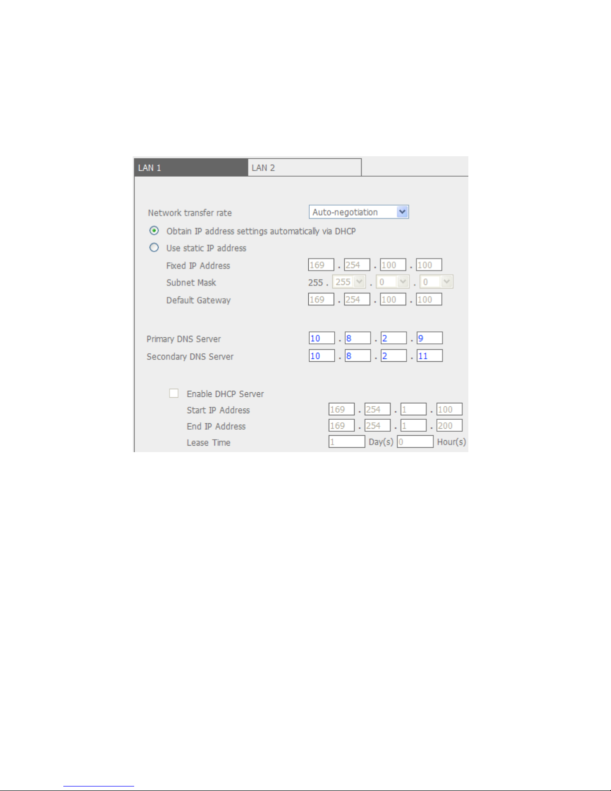
z Network Transfer Rate
You can select auto-negotiation (default), 1000 Mbps, or 100 Mbps. It is
recommended to use the default setting that the server will determine network
speed automatically.
z Obtain IP address settings automatically via DHCP
If your network supports DHCP, VioStor will use DHCP protocol to retrieve the
IP address and related information automatically.
z Use static IP address
To use fixed IP address for network connection, enter fixed IP address, subnet
mask, and default gateway.
z Primary DNS Server
Enter the IP address of primary DNS server that provides DNS service for
VioStor in external network.
z Secondary DNS Server
Enter the IP address of secondary DNS server that provides DNS service for
VioStor in external network.
Enable DHCP Server
If no DHCP is available in the LAN where the VioStor locates, you can enable this
function to enable the VioStor as a DHCP server and allocate dynamic IP address to
DHCP clients in LAN.
You ca n set the range of IP addresses alloca ted by DHCP server and the lease time.
Lease time refers to time that IP address is leased to the clients by DHCP server.
When the time expires, the client has to acquire an IP address again.
Note: If there is an existing DHCP server in your LAN, do not enable this function.
Otherwise, there will be IP address allocation and network access errors.
54
Page 55

5.3.2 DDNS (Dynamic Domain Name) Service
DDNS service enables users to connect VioStor via domain name directly. There is
no need to know the real IP address of the server. T o enable DDNS service, you have
to register a DDNS account from a DDNS provider. Please refer to Appendix C
.
Note: VioStor currently supports the DDNS service provided by:
1. DynDNS (http://www.dyndns.org/)
2. update.ods.org
3. members.dhs.org
4. www.dyns.cx
5. www.3322.org
6. www.no-ip.com
7. ipcam.jp
55
Page 56

5.3.3 File Services
You can enable SMB/ CIFS file service, W eb File Manager and FTP service to access
the recorded video files. These settings are enabled by default.
If your VioStor is installed behind the router, you could enable FTP port mapping, so
that users from external network can access VioStor via FTP (please refer
to Appendix F
).
Passive FTP Port Range
You can use the default port range (55536-56559) or define a port range larger than
1023. When using this function, please make sure you have opened the configured
port range on your router or firewall.
Respond with external IP address for passive FTP connection request
When passive FTP connection is in use and the VioStor is configured under a router,
if the remote computer cannot connect to the Vi oStor via W AN, you can enabl e this
function. By enabling this function, the FTP service replies the manually specified IP
address or automatically detects the external IP address so that the remote
computer can connect to the VioStor successfully.
56
Page 57

5.3.4 Host Access Control
Specify the connections to be allowed and denied to access VioStor. Choose one of
the following options to restrict access from a network or an IP address (host) to the
server:
1. Allow all connections (Default setting)
Allow connection from all hosts to the server.
2. Allow connections from the list only
Allow connection from hosts specified on the list only.
When this function is enabled, you can only use PC that the IP address is listed
on the connection list to connect or find VioStor. The IP address not included in
the list will not be able to detect VioStor not listed in allowed con nections.
Note:
3. Deny connections from the list
Deny connection from hosts specified on the list.
Make sure your PC is added in the list of hosts allowed to connect to the server.
Otherwise, VioStor will disconnect your PC when you apply the new settings.
Note:
57
Page 58

5.3.5 Protocol Management
T o assign a specific port for accessing the VioStor via the web browser, please enable
the option “Specify HTTP port number” and enter the port number. The default
setting is 80.
RTP (Real-time Transfer Protocol) is a standardized packet format for delivering
real-time audio and video data of network cameras over the Internet. The real-time
data transfer is monitored and controll ed by R TP (also R T CP). T he default setting i s
6100-6199. If your network cameras use different R TP ports, please enable “Specify
RTP port range” and enter the port numbers.
Note: Make sure you have opened the ports you set on the router or firewall to
ensure normal monitoring and recording.
58
Page 59

5.3.6 View Network Settings
You can view current network settings and status of VioStor in this section.
59
Page 60

5.4 Device Configuration
You can configure SATA disk, USB disk, and UPS settings in this section.
5.4.1 SATA Disk
This page shows the model, size and current status of the disk(s) installed on
VioStor . Y ou can format and check disks, and scan bad blocks on the disks. When the
SATA disks are formatted, VioStor will create the following default share folders:
z record_nvr: The folder for saving regular recording files
z record_nvr_alarm: The folder for alarm recording
60
Page 61

You can create the disk volume of the following type:
z Single Disk Volume
Each disk will be used as a standalone disk. However, if a disk is damaged, all
data will be lost.
Note: If there is only one hard disk, please install it in the tray of HDD1.
z RAID 1 Mirroring Disk Volume
RAID 1 (mirroring disk) protects your data by automatically backing up the
contents of one drive onto the second drive of a mirrored pair. This protects
your data if one of the drives fails. Unfortunately, the storing capacity is equal
to a single drive, as the second drive is used to automatically back up the first.
Mirroring Disk is suitable for personal or corporate use to store important data.
z RAID 0 Striping Disk Volume
RAID 0 (striping disk) combines 2 or more drives into one larger disk. It offers
the fastest disk access but it does not have any protection of your data if the
striped array fails. The disk capacity equals the number of drives in the array
times the size of the smallest drive. Striping disk is usually used to maximize
your disk capacity or for fast disk access but not for storing important data.
z Linear Disk Volume
You ca n combine two or more disks into one larger disk. During file sa ving, the
file will be saved on physical disks sequentially but does not have a disk failure
file protection function. The overall capacity of linear disk is the sum of all disks.
Linear disk is generally used for storing large data and is not appropriate to use
for file protection of sensitive data.
61
Page 62

5.4.2 RAID Management Tool
RAID management tool allows you to carry out capacit y expansion, RAID migration,
or spare drive configuration with the original drive data reserved.
z Expand capacity
This function enables drive capacity expansion by replacing the drives in a
configuration one by one. This option is supported for the following drive
configurations:
- RAID 1 expansion
z Migrate
This function enables a drive configuration to be migrated to a different RAID
configuration. It is supported for the following drive configurations:
- Migrate single drive to RAID 1
For detailed operation, please click the “Description” button on the management
interface to view the detailed operation instructions.
62
Page 63

5.4.3 USB Disk
VioStor supports USB disks for backup storage. Connect the USB device to the USB
port of the server , when the device is succe ssfully detected, the details will be shown
on this page.
63
Page 64

5.4.4 UPS
If there is UPS, you can enable UPS support. If the AC power is abnormal, the
system will shut down according to the settings. If the time has not reached and the
power of the UPS is not sufficient, the system will shut down immediately to protect
the server.
* It is recommended to connect UPS to one of the USB ports at the back of server.
z Enable UPS Support
Check this option to enable UPS support. You can configure the time when the
system should shut down when AC power status is abnormal. In gen e ral, UPS
can supply power for 5-10 minutes when AC power is down depending on the
maximum load and number of connected devices of the UPS.
z UPS Model
Select the UPS model on the list. If your UPS is not available on the list, please
contact the distributor or the technical support of QNAP.
z IP Address of UPS
If you select “APC UPS with SNMP Management” , please enter the IP address of
the UPS.
Note: It is recommended to use APC Smart-UPS 700+ APC Network
Management Card.
64
Page 65

5.5 User Management
The server can be accessed by multiple users. For easier management and better
control of users’ access right, you have to organize users, user groups and their
access right control.
Note: The server supports up to 32 users (including system default users). Y ou can
create new users when necessary.
There are two types of users:
A. Administrators
By default, administrator has access to system administration and cannot be
deleted. Newly created user with system administration right can be deleted.
B. User
User has monitoring right only but cannot enter administration page.
You can perform the following actions for user management:
1. Create user
2. Edit user
3. Delete user
65
Page 66

5.5.1 Create user
User Name
The user name cannot be pure number. It must not exceed 32 characters. It is
case-insensitive and supports double-byte characters, such as Chinese, Japanese,
and Korean except:
" / \ [ ] : ; | = , + * ? < > ` '
Password
The password is case-sensitive and can be 16 characters long at maximum. It is
recommended to use a password of at least 6 characters.
Enable this user to perform system administration
Assign administration right to the user.
Camera Access Control
Enable user to monitor the camera or playback the recording.
66
Page 67

5.5.2 Edit User
Select a user on the list and click Edit. You can change the password, assign system
administration and camera access control. However, the user name cannot be
changed.
5.5.3 Delete User
To delete a user, select a user on the list and click Delete.
Click OK to confirm.
Note: System administrator cannot be deleted.
67
Page 68

5.6 Camera Settings
You can configure network camera, recording, schedule, alarm, and advanced
settings.
5.6.1 Camera Configuration
Please follow the steps below to configure the network cameras.
1. Select a camera number.
2. Select the camera brand.
3. Select the camera model.
4. Enter the camera name.
5. Enter the IP address or domain name of the camera.
6. Enter the user name and password to login the camera.
7. Select to enable recording or not.
8. Click Apply to save the settings.
Note:
1. For detailed supported camera list, please refer to Appendix D
.
68
Page 69

2. All the settings will not take effect until you click Apply button. When applying
changes, recording operation will stop for a while (maximum 1 minute) and
then restart.
3. Click “Search” to search for the IP cameras in the local network. Select a
channel for the camera and click “Add” to add the camera. By using the search
function, the camera model and the IP address are filled in automatically.
Click “Close” to close the search results.
5.6.2 Recording Settings
Select a camera on the list and configure the recording resolution, frame rate, and
quality. You can also enable manual recording. Click Apply to save the settings.
1. Resolution: Select the recording resolution.
2. Frame rate: Adjust the frame rate for recording. Note that the frame rate of
the camera may be affected by the traffic of the network.
3. Quality: Select the image quality for recording. Higher quality consumes more
disk space.
4. (Option) Audio recording: To enable audio recording, click Enable audio
recording on this camera.
69
Page 70

5. Estimated storage space for recording: The number of estimated storage
space for recording is only for reference. The actual space consumed de pends
on the network environment and camera performance.
6. Manual recording: To allow manual activation and deactivation of manual
recording function on monitoring page, enable this option.
Note:
1. Starting and stopping manual recording will not influent scheduled or alarm
recording tasks. They are independent processes.
2. All the settings will not take effect until you click the Apply button. When
applying changes, recording operation will stop for a while (maximum 1 minute)
and then restart.
70
Page 71

5.6.3 Schedule Settings
You can select continuous recording or scheduled recording. The default setting is
continuous recording. To set up a recording schedule, please select a camera
number on the list. Then select the date and time and click Add. Click Apply to add
the setting for the camera or click Apply to all cameras to apply to setting to all
cameras. To delete a schedule, click Remove on the schedule list.
Note:
1. You can add up to 15 schedules.
2. All the settings will not take effect until you click the Apply button. When
applying changes, recording operation will stop for a while (maximum 1 minute)
and then restart.
71
Page 72

5.6.4 Alarm Settings
You ca n enable alarm recording of the cameras. Recording will be triggered by alarm
input of the camera or motion detected by the camera.
When you enable the option “Activate alarm recording only on selected schedule”,
alarm recording will be activated only when alarm input is triggered or motion is
detected within the preset schedule. You could test the camera setting by clicking
Test. Click Apply to add the setting for the camera or click Apply to all cameras
to apply to setting to all cameras.
Note: All the settings will not take effect until you click the Apply button. When
applying changes, recording operation will stop for a while (maximum 1 minute) and
then restart.
72
Page 73

5.6.5 Advanced Settings
You can configure advanced recording settings in this section.
z Maximum period for each recording file: Configure the maximum length of
each recording file (maximum 15 min).
z When the available storage is less than …GB: Select the action to take
when the available storage is less than the preset level. You can select to
overwrite the oldest recordings or stop writing new recordings.
z Keep alarm recordings for at least …day(s): Specify the number of days
that alarm recordings will be retained. This will prevent the recording files from
being overwritten when the free storage space is insufficient.
z Remove recordings after …day(s): Enter the number of calendar days for
VioStor to keep the recording files.
Please make sure your storage capacity is enough for saving the data for the
number of calendar days you set. When recording da ta has reached the expiry
date, expired video files will be deleted. For example, if you set to delete
recording data after 7 calendar days, on the 8th day, files recorded on the first
day of each camera will be deleted so that VioStor can start to save da ta of the
8th day.
73
Page 74

z Pre/Post Alarm Recordings
Start recording video …second(s) before the event occurs: Enter
the number of seconds to start recording before an event occurs.
Stop video recording …second(s) after the event ends: Enter the
number of seconds to stop recording after an event ends.
The maximum number of seconds for the above settings is 300, i.e. 5 minutes.
Note: All the settings will not take effect until you click the Apply button. When
applying changes, recording operation will stop for a while (maximum 1 minute) and
then restart.
74
Page 75

5.7 System Tools
System Tools enable you to optimize the system maintenance and management.
You can set alert notification, restart or shut down the server, configure hardware
settings, system update, back up/ restore/ reset settings, set E-map and do ping
test.
5.7.1 Alert Notification
Enter the e-mail address of the administrator and the IP address of the SMTP server.
In case of warning or malfunction, e.g. power outage, a drive is unplugged, an
e-mail will be sent to the administrator automatically. You can go to Event Logs to
check the details of all errors and warnings.
Note: It is recommended to send a test e-mail to make sure you can receive the
alert mails.
75
Page 76

5.7.2 Restart/ Shut Down
Follow the steps below to restart or shut down the server.
1. Enter the administration page and select Restart/ Shutdown in System
Tools.
2. Click Restart to reboot the server or Shut Down to turn off the server.
5.7.3 Hardware Settings
You can enable or disable the hardware functions of the server.
76
Page 77

z Enable configuration reset switch
By enabling this option, you can press the reset button for 5 seconds to reset
the administrator password and system settings to default.
Note: The configuration reset switch is enabled by default. When this option is
disabled, please make sure you have kept your password sa fely. Otherwise, the
server cannot be reset anymore if the password is lost.
z Enable hard disk standby mode
When this function is enabled, hard disk will go to standby mode if there is no
access within the specified period.
z Auto power on when power resumes after power loss
When this function is enabled, the server will turn on automatically when the
power resumes after power loss.
z Enable front video backup button
VioStor supports direct copy of recording data on the server to the connected
USB device via the USB port. Y ou c an set the number of days that the video is
recorded to copy to the device.
To use this function, please follow the steps below:
1. Set the number of days that the latest recordings should be backed up. If
3 days are entered, the recordings of today , yesterda y and the day before
yesterday will be backed up.
2. Connect a USB storage device, e.g. USB disk drive to the front USB port of
VioStor.
3. Press and hold the one touch auto video backup button for 3 seconds.
The recording data on VioStor will start to be copied to the USB device
instantly . If the USB de vice is recognized, the USB LED glows in blue. The
USB LED will blink in blue when the data is being copied. The LED will
become blue again when data copy is finished. Y ou can then safely remove
the device.
Note: Video backup function supports only USB device of 10GB storage
capacity or above.
z Enable light signal alert when the free size of SATA disk is less than the
value
The Status LED flashes red and green when this function is enabled and the
free space of the SATA disk is less than the value. The range of the value is
1-51200 MB.
z Enable alarm buzzer
Enable this option. The system will sound when an error occurs.
z Smart Fan configuration
77
Page 78

After enabling the smart fan, the fan rotation speed is automatically adjusted
according to the server temperature. It is recommended to enable this option.
By manually setting the fan rotation speed, the fan rotates at the defined speed
continuously.
5.7.4 System Update
Before updating system firmware, please make sure the product model and
firmware version are correct. Follow the steps below to update firmware:
1. Download the release notes of the same version as the firmware from QNAP
website http://www.qnapsecurity.com/
. Read the release notes carefully to
make sure you need to upgrade the firmware.
2. Before upgrading system firmware, back up all disk data on the server to avoid
any potential data loss during system update.
3. Click the [Browse…] button to select the correct firmware image for system
update. Click Update System to update the firmware.
System update may take several minutes to complete depending on the network
connection status. Please wait patiently. The system will inform you when system
update is completed.
When performing system update, please make sure the power supply is at steady
state. Failed to do so may cause the system unable to start up.
Note: If the system is running properly, you do not need to update the firmware.
QNAP is not responsible for any forms of data loss caused by improper or illegal
system update.
78
Page 79

5.7.5 Backup/ Restore/ Reset Settings
z To backup all settings, including user accounts, server name and network
configuration etc., click Backup and select to open or save the setting file.
z T o restore all settings, click Browse to select a previously saved setting file and
click Restore to confirm.
z To reset all settings to default, click Reset. All data on the disk(s) will be
deleted.
79
Page 80

5.7.6 Remote Replication
You can use the remote replication feature to copy the recording dat a of the local
VioStor to a remote QNAP network attached storage (NAS, TS-209). The remote
QNAP NAS is hereafter referred to as “the remote storage device”.
Note: Before using this function, please make sure the Microsoft networking service
of the remote storage device is enabled, and the corresponding path and user
access right have been correctly configured.
Login VioStor and enter “System Tools/ Remote Replication” page.
80
Page 81

Configure the backup data, remote backup server settings, and backup schedule of
the remote storage device in sequential order.
Enable remote replication (support multiple choices)
In the above example, the system only copies the alarm recording data of the latest
3 days to the remote storage device.
z Check the box “Enable remote replication” to activate this feature. The sys tem
executes automatic backup of recording data to the remote storage device
according to the settings.
z When you select “Back up alarm recordings only (instead of all recordings)”,
the system will only copy alarm recording data to the remote storage device. If
this option is unchecked, the system will backup all recording data to the
remote storage device.
z When you select “Back up the recordings of the latest…day(s) only” and enter
the number of days, the system will back up the latest recording data to the
remote storage device automatically according to your settings. If this option is
unchecked, the system will copy all recording data to the remote storage
device.
81
Page 82

Configure your remote storage server
Note: It is recommended to execute the “Remote host testing” function to verify the
connection to the remote storage device is successful.
Configure the remote replication schedule
For example, to enable the system to copy recording data automatically to remote
storage device at 01:15 every Monday, please do the following:
Check the box “Replication Schedule”, select “Weekly”, enter 01 Hour: 15 minut e,
and select “Monday”.
Backup Options
z Select “Replication Now”, the system backs up recording data to remote
storage device immediately.
z Select “Overwrite the oldest recordings when the available storage on the
remote host is less than 4GB” , the system o verwrites the oldest recording data
when the free space on the server is less than 4GB.
z Select “Perform mirroring replication by deleting extra files on the remote
replication”, the system syncs the recording data between VioStor and the
remote storage device and delete any extra files on the remote destination.
82
Page 83

z When the above options are all checked, the system executes remote
replication immediately. It first judges if there are extra files on the remote
location that are different from the local source. If yes, the ext ra files will be
removed. After that, the system executes recording data backup and verifies if
the free space of the internal hard disk drive is less than 4GB. If the free
storage capacity is larger than 4GB, remote replication will be executed
immediately . If the free storage space is less than 4GB , the system deletes the
recording data of the oldest day and executes remote replication.
z The system displays the latest 10 remote replication records for you to analyze
the status and troubleshooting.
In the above example:
1. When the status is shown as “Failed (Remote access error)”: You can check the
remote storage device is running or the network settings are correct.
2. When the status is shown as “F ailed (An internal error occurred)”: Y ou can check
the hard drive status of VioStor or check the Event Logs.
Note:
The time required by VioStor to replicate data to remote storage device varies to the
network environment. If the remote replication time is too long, some recording
files may be overwritten by the system. To avoid this, it is recommended to refer to
the status messages to analyze the time needed for remote replication and adjust
the replication schedule accordingly.
83
Page 84

5.7.7 Hard Disk SMART
This page enables users to monitor hard drive health, temperature, and usage
status by the hard disk S.M.A.R.T. mechanism.
Select the hard drive and you can view the following information by clicking the
corresponding buttons.
Field
Description
Summary Displays the hard drive smart summary and the latest test
result.
Hard disk
information
Displays the hard drive details, e.g., model, serial number,
drive capacity, etc.
SMART information Displays the hard drive SMART. Any items that the values
are lower than the threshold are regarded as abnormal.
Test To perform quick or complete hard drive SM ART test and
display the results.
Settings To configure temperature alarm. When the hard drive
temperature is over the preset values, the system records
error logs.
You can also configure quick and complete test schedule.
The latest test result is shown in the Summary page.
84
Page 85

5.7.8 E-map
You can upload an E-map to VioStor to illustrate the location of the cameras.
1. To upload an E-map, click Browse… and select the E-map file. Then click
Upload.
2. You can change the caption for the E-map and click Apply.
3. After uploading the E-map, click Test to view the map.
5.7.9 Ping Test
To test the connection to a specific IP address, enter the IP address and click Test.
85
Page 86

5.8 Logs & Statistics
5.8.1 Event Logs
The server can store thousands of recent event logs, including warning, error, and
information messages. In case of system malfunction, event logs (only in English)
can be retrieved to analyze system problems.
Click “Save” to save the logs as csv file. Click “Delete” to clear all logs.
5.8.2 Surveillance Logs
This page shows the surveillance logs such as camera connection, motion detection,
and camera authentication failure.
86
Page 87

5.8.3 On-line Users List
This page shows the information of the currently active users, e.g. the user name,
IP address, and login time.
5.8.4 Historical Users List
This page shows the information of the users who have logged in the system
including the user name, IP address, login time, and the services they have
accessed etc.
87
Page 88

5.8.5 System Connection Logs
The logs of connections to the server via samba, FTP, AFP, HTTP, HTTPS, Telnet, and
SSH are recorded in this page.
You can select to start or stop logging. The file transfer performance can be slightly
affected by enabling the event logging.
5.8.6 System Information
This page shows the system information, e.g., CPU usage, memory, and system
temperature.
88
Page 89

Chapter 6. System Maintenance
This section provides a general overview on system maintenance.
6.1 Reset Administrator Password and Network Settings
T o reset the administrator password and ne twork settings, press the reset button of
the server for five seconds. A beep sound will be heard.
After resetting the system, you can login the server with the default user name and
password:
Note: To reset the system by the reset button, the option “Enable configuration
reset switch” in Hardware Settings must be activated.
Default user name: admin
Password: admin
89
Page 90

6.2 Power Outage or Abnormal Shutdown
In case of power outage or improper shutdown of the server , the server will resume
to the state before it is shut down. If your server does not function properly after
restart, please do the following:
1. If the system configuration is lost, configure the system again.
2. In the event of abnormal operation of the server, contact customer service for
technical support.
To avoid the above situations, please back up your data periodically and make sure
you have done the following:
z Follow the instructions described in Chapter 5.7.2
to restart or shut down the
server.
z If there is an anticipated power outage, back up all important data and turn off
the server properly until power supply is resumed.
6.3 Mirrored Disk Hot Swapping
VioStor supports hot swapping. When a hard disk of RAID-1 mirroring disk volume
fails, the failed disk can be replaced by a new one immediately without shutting
down the system, and the recording data can be reserved. However, if the hard
disks are working properly and recording is in process, do not hot swap the disks to
avoid damage to the disks or recording files.
90
Page 91

Chapter 7. Troubleshooting
1. The monitoring screen did not display.
Please check the following:
A. Check if you have installed ActiveX when logging in the monitoring page.
Set the security level to “Medium” or lower in Internet Options of IE
browser.
B. Make sure VioStor is turned on and the network is correctly connected.
C. The IP address of VioStor does not conflict with other devices in the same
subnet.
D. Check the IP address settings of VioStor and your computer. Make sure
they are in the same subnet.
2. In the monitoring page, unable to view live video on one of the
cameras.
Please check the following:
A. The IP address, name, and password entered in the camera configuration
page are correct. You can use the Test function to verify the connection.
B. When the PC and the network camera are in the same subnet, while
VioStor is in another one, you cannot view the monitoring screen from the
PC. You can solve the problems by the following methods:
Method 1: Enter the IP address of the network camera as the WAN IP in
VioStor.
Method 2: Configure the router to allow internal access to the public IP
address and the mapped ports of the network cameras.
3. Recording is not working properly.
A. Make sure the hard disk tray is correctly locked in VioStor.
B. When only one hard disk is installed, make sure the disk is installed in the
tray of hard disk 1. Hard disk 1 should be installed on top of hard disk 2.
C. Check if the recording function is enabled in Camera Configuration page
(the function is enabled by default). Mak e sure the IP address, name, and
password are correct.
D. If the above items are verified to work properly while the status LED blinks
in green, the hard disk(s) may be damaged or cannot be detected. Please
turn off the server and install a new hard disk.
91
Page 92

Note: If you have updated the configurations of VioStor, recording will be
stopped temporarily and restart again shortly.
4. I cannot login the administration page.
Please check if you have the administrator authority. Only administrators are
allowed to login VioStor.
5. The live video is not clear or smooth sometimes.
A. The image quality may be restricted and interfered by the actual network
traffic.
B. When there are multiple accesses to the camera or the VioStor server , the
image quality will be reduced. And it is recommended to have three
simultaneous connections to the monitoring page at maximum. Fo r better
recording performance, please do not open too many IE browsers to view
the live video.
C. The same camera may be shared by multiple VioStors for recording at the
same time. Please use dedicated cameras.
6. The alarm recording does not function.
A. Please login the administration page and go to Camera Settings-Alarm
Settings. Make sure alarm recording is enabled for the camera.
B. When using Panasonic BB-HCM311 cameras, the camera firmware must
be upgraded to v1.3 for alarm recording to work properly.
C. If VioStor is installed behind a router while the network camera is not,
alarm recording will not work.
D. When alarm recording is enabled, make sure you have configured the
number of days that alarm recordings will be retained in Camera
Settings-Advanced Settings. Otherwise, the recordings may be
overwritten.
7. The estimated storage space for recording displayed in Recording
Settings page is different from the actual value.
This estimated value is for reference only. The actual disk space may vary
according to the image contents, network environment, and the performance
of the cameras.
92
Page 93

8. The screen is displayed abnormally with strange horizont al lines when
the resolution of Panasonic BB-HCM381 camera is set as 640x480.
This is due to the interlaced scanning design of the camera. Please login the
camera’s configuration page and go to Setup->Camera->Vertical Resolution.
Then configure the setting as 240.
9. The E-map cannot be displayed correctly.
Please check the file format. VioStor supports E-map in JPEG only.
10. I cannot find my VioStor in QNAP Finder.
A. Check if VioStor is turned on.
B. Check the network connection of the computer and VioStor.
C. Refresh QNAP Finder and check the IP address of VioStor. Make sure you
have turned off all firewall software on your computer.
11. The changes to the system configurations cannot take effect.
After changing the settings in administration page, click the Apply button to
apply the changes.
12. The monitoring page cannot be fully displayed in Internet Explorer.
If you are using the zooming function of Internet Explorer 7, the page may not
be displayed properly. Please click F5 to refresh the page.
13. I cannot use the SMB, FTP, and Web File Manager of VioStor.
A. Please go to Network Settings-File Services page and check if these three
functions are enabled.
B. When VioStor is installed behind a router and the access to VioStor is
outside the router , you will not be able to use SMB and FTP services. Please
refer to Appendix E
for details.
14. The server takes too long to restart.
When the server has been restarting for more than 5 minutes, please turn off
the power and turn on the server again. If the problem persists, please contact
the technical support.
93
Page 94

Appendix A Hard Disk Recommendation List
This product works with 3.5" SA T A hard disk drives from major hard disk brands. F or
the HDD compatibility list, please visit http://www.qnapsecurity.com/
.
Note: QNAP disclaims any responsibility for product damage/ malfunction or
data loss/ recovery due to misuse or improper installation of hard disks in any
occasions for any reasons.
94
Page 95

Appendix B Dynamic Domain Name Registration
VioStor supports DDNS service provided by DynDNS. You can go to DynDNS
website http://www.dyndns.org/
to register a dynamic domain name.
Configure and activate DDNS service to enable the Internet users to access your
VioStor via this dynamic domain name. When the ISP assigns a new WAN IP address,
VioStor will update the new address to the DynDNS server automatically.
95
Page 96

Registration Procedure
Please follow the steps below to register a dynamic domain name. This guide is for
reference only. If there are any changes, please refer to the instructions or
documents on the web site.
1. Open the browser and connect to http://www.dyndns.com/
. Click Create
Account to begin registration.
2. Enter the user name, email address, and password to create an account for
DDNS service. Please verify your email address to receive the confirmation
message from the server.
96
Page 97

3. Select to accept the terms of service.
4. Configure the mailing lists if necessary. Then click Create Account.
5. When your account is successfully created, a confirmation message will be sent
to your e-mail address. Please follow the instructions in the e-mail to activate
your account within 48 hours. When you ha ve finished the confirmation process,
you can apply for your own dynamic domain name. Please refer to the website
of the DDNS provider for more information.
97
Page 98

Appendix C Product Specifications
Software Specification
Video
Display Mode 1/ 4/ 6/ 8/ 9/ 10/ 12/ 16/ 20-channel display,
Picture-in-Picture, sequential mode
Recording Cameras
Number
VioStor-2008: Up to 8 channels
VioStor-2012: Up to 12 channels
Compression Format Motion-JPEG/ MPEG-4/ H.264 (depends on the IP camera)
Video Setting Resolution, Quality, Frame Rate
E-map Upload E-map (JPEG)
Recording
Continuous/ manual/ schedule/ alarm recording, alarm
recording schedule
Recording Mode
Buffer Storage for
Alarm Images
(before and after
events)
Pre-recording: 300 sec/ Post‒recording: 300 sec (Total 600
sec/
10 min)
Recording
Performance
VioStor-2008: Up to 240 fps at D1(720x480) or
VGA(640x480)
VioStor-2012: Up to 360 fps at D1(720x480) or
VGA(640x480)
* Real performance may vary in different environment
Megapixel Recording Supports megapixel cameras (up to 8-megapixel)
File format AVI (can be played by Windows Media Play er)
Snapshot Yes
Playback
Playback Channel Max 4-channel playback at the same time
Play , pause, stop, reverse play, next/ previous frame, next/
previous video file, different speed control
Playback Mode
Display Mode Single playback view, 4 playback views
Search Mode By date, time, alarm event
Playback
Enhancement
Full screen display, video snapshot, digital zoom, screen
recording and convert into one AVI file
Download Click to download recorded files from web page
Storage
98
Page 99

Disk Management
z Single disk, RAID 0 (Disk Striping), RAID 1 (Disk
Mirroring), and JBOD (Linear Disk Volume)
z Online RAID Capacity Expansion
z Online RAID Level Migration
z HDD S.M.A.R.T.
z Bad blocks scan
z Services: Web File Manager, FTP, SMB/CIFS
Network
HTTP, TCP/IP, SMTP, DHCP, Static IP, DNS, DDNS, FTP, NTP,
UPnP, Failover, Load-balancing, Multi-IP setting
Support
Camera IP Address &
Port
Allow setting LAN/WAN IP address of each camera
Dual Gigabit LAN
z Failover: In case one of the LAN network fails, the
packets sent to the NVR will be handled by the other
LAN interface
z Load-balancing: Link aggregation is supported to
increase the transfer speed
z Multi-IP setting: The NVR can serve different network
groups in two different subnets
Utility Software QNAP Finder: Discovery and quick setup for NVR
Security
Operation System Linux-embedded, free from PC crash and virus attack
Record of the users currently logged on and previously
logged on to the NVR
On-line Users List
Specify the connections to be allowed and denied to access
NVR
Host Access Control
The right to monitor and playback each camera can be
separately defined for each user (up to 32 users)
User Management
Alert Notification E-mail, buzzer, event logs
UPS Support APC/ MGE (USB type UPS)
Detailed event logs of system warning, hard disk error,
network disconnection, UPS status, and users’ networking
services, and data access
Event Logs
Client PC Requirement
CPU
z Motion-JPEG format (up to 12 channels): Pentium 4
CPU 2.4 GHz or above
z MPEG-4/ H.264 format (up to 12 channels): Dual core
CPU 2.4 GHz or above
99
Page 100

For higher surveillance performance, please select more
advanced PC models.
Memory 1 GB or above
Operation System Microsoft® Windows® XP/ Vista (32-bit)
Web Browser Internet Explorer 6.0 or later
Network Interface 10/100 Mbps or above
View Resolution Suggested 1024 x 768 pixels or above
English/ French/ German/ Italian/ Japanese/ Spanish/
Simplified Chinese/ Traditional Chinese/ Danish/ Dutch/
Finnish/ Korean/ Norwegian/ Polish/ Portuguese/ Russian/
Swedish
Language Support
Hardware Specification
Processor Intel Processor 1.6GHz
Memory 1GB DDRII RAM, 128MB flash (DOM)
HDD Capacity 2 x 3.5" SATA I/II HDD, up to 4TB
(the standard system is shipped without HHD)
HDD Tray 2 x hot-swa ppable and lockable tr ay
LAN Port 2 x Gigabit RJ-45 Ethernet port
LED Indicators HDD 1, HDD 2, LAN, eSATA
USB 3 x USB 2.0
Front: for USB storage device (One T ouch Auto Vi deo Backup)
Back: for UPS device
eSATA 2 x eSATA port (back); reserved
Buttons Power, one touch auto video backup, reset
Alarm Buzzer System warning
Form Factor Tower
Dimensions 150(H) x 102(W) x 216(D) mm
5.91(H) x 4.02(W) x 8.5(D) inch
Color Box Shipping
Weight
2.92 Kg (6.44 lb)
Operation
Environment
Temperature 0~40˚C
Humidity 0~95% R.H.
Power Supply External power adaptor, 60W; input:110~240V
Power Consumption 37 ~ 44W Write/Read
Secure Design K-Lock security slot for theft prevention
VGA Reserved
100
 Loading...