

Page 1
READ AND SAVE THESE INSTRUCTIONS
MODEL MM648 & MM748 F ANS AND
MODEL MM664IC, MM667IC & MM667ICF
F AN / LIGHTS
DESCRIPTION
Models MM664IC, MM667IC, MM667ICF, MM648 and MM748 fans
are intended for use in bathrooms. However, they can also be used
in other areas where ventilation is required. Models MM664IC,
MM667IC, and MM667ICF are U.L. Listed Type I.C. (Inherently
Protected) for installation in insulated ceilings.
UNPACKING
Unpack carefully. If there are missing components or hidden
damage, immediately contact your distributor or the delivering
carrier concerning discrepancies.
1.
Do not use this fan with any Solid-State speed control device.
2. Use this unit only in the manner intended by the
manufacturer. If you have questions, contact the
manufacturer.
3. Before servicing or cleaning unit, switch power off at service
panel and lock service panel to prevent power from being
switched on accidentally.
4. Installation work and electrical wiring must be done by
qualified person(s) in accordance with all applicable codes and
standards, including fire-rated construction.
5. Sufficient air is needed for proper combustion and exhausting
of gases through the flue (chimney) of fuel burning equipment
to prevent back drafting. Follow the heating equipment
manufacturer’s guideline and safety standards such as those
published by the National Fire Protection Association (NFPA),
and the American Society for Heating and Air Conditioning
Engineers (ASHRAE), and the local code authorities.
6. When cutting or drilling into wall or ceiling, do not damage
electrical wiring or other hidden utilities.
7. Ducted fans must always be vented to the outdoors.
8. If this unit is installed over a tub or shower, it must be marked
as appropriate for the application and connected to a GFCI
protected branch circuit. See product label.
9. NEVER place a switch where it can be reached from a tub
or shower.
10. CAUTION:For General Ventilation Only! Do not use to
exhaust hazardous or explosive materials or vapors.
11. Not for use in kitchens.
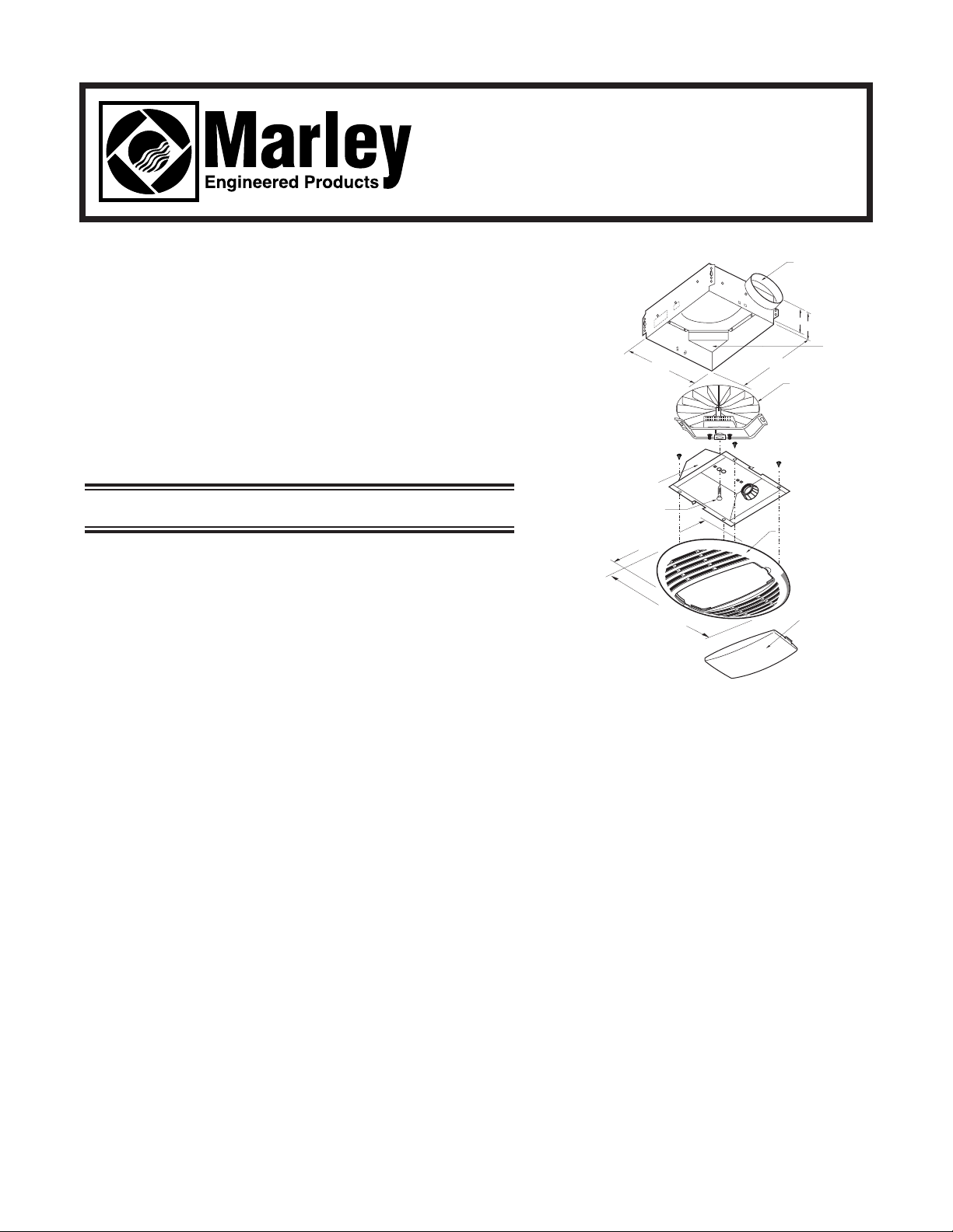
FIG. 1
MODELS
MM664IC
MM667IC
MM667ICF
IMPORTANT SAFETY INSTRUCTIONS
WARNING:
TO REDUCE RISK OF FIRE,ELECTRICAL SHOCK OR
INJURY T O PERSONS, OBSERVE THE FOLLOWING:
12 1/4"
10
3/4"
6 3/4"
5 1/2"
6 1/4"
7 3/4"
MOTOR AND
BRACKET
ASSEMBLY
OUTLET
BOX
4" AIR DISCHARGE
OUTLET
GRILLE
REFLECTOR
SCREW
LENS
Page 2
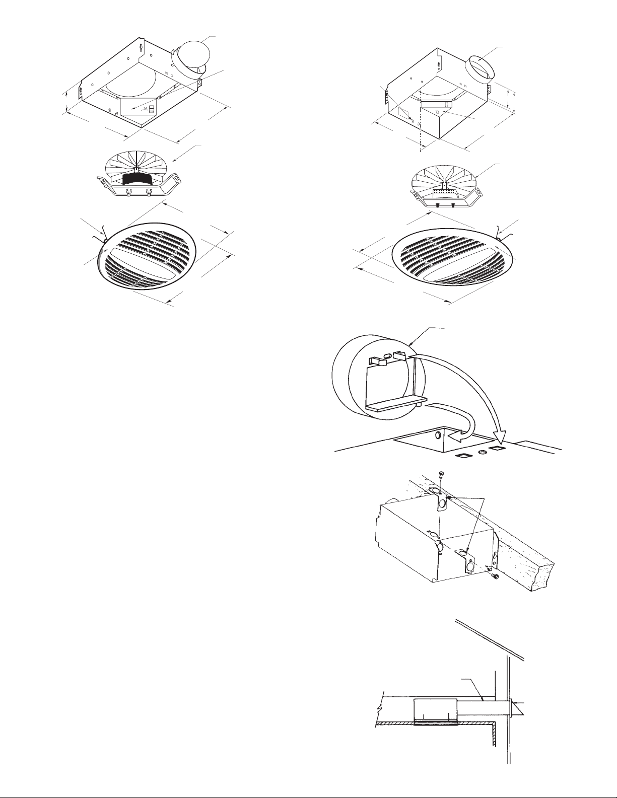
FIG. 2
MODEL
MM648
FIG. 3
MODEL MM748
NOTE; To install grilles,
pinch springs together and
slide into grille mounting slot.
TOOLS
Installation of your bath fan is easy. No special technical
knowledge is needed; only a few ordinary tools are required:
Screwdriver
Hammer
Saber saw, Keyhole saw, or Jig saw
Electric drill with bit
Wire cutters
Wire stripper
Wire nuts and general electrical supplies
Safety glasses
Ruler and straight edge
All hand tools should be insulated. Power tools should display the
U.L. Listing Mark.
1. Attach duct adapter to housing by first inserting pin on duct
adapter into round hole in top of housing, then pivot and align
two locking tabs with small rectangular holes. See Fig. 4.
Press tabs firmly into place.
NOTE: The attachment of the duct adapter to the housing maybe
reinforced, if desired, by installing a #8 self-tapping screw through
the obround hole in the duct adapter and the small round hole in
the housing.
2. Attach housing to joist with screws or nails. Housing is
stamped to show a line at 3/4” for standard sheetrock and
plaster and 3/8” for drywall. See Fig. 5.
3. Run 120VAC, 60Hz power leads from wall switch or timer
to appropriate knockout in housing. Use a BX or Romex
connector on outlet box.
WARNING:SUPPLY WIRING MUST BE U.L. RATED 90°C
FOR FAN/LIGHT MODELS.
NOTE: The knockout support may be reversed, if desired, to
open alternate knockout hole and cover unused hole. See Fig. 5.
If both holes are to be used, simply remove knockout.
NEW HOME INSTALLATION
-2-
FIG. 4
FIG. 5
FIG. 6
DUCT ADAPTER
KNOCKOUT
SUPPORT
ROUND
DUCT
WALL
CAP
6 3/4"
5 1/2"
6 1/4"
7 3/4"
MOTOR AND
BRACKET
ASSEMBLY
UNITS ONLY)
GRILLE
MTG
SLOTS
OUTLET
BOX
4" AIR DISCHARGE
OUTLET
12 1/4"
10
3/4"
SPRING
CLIP
GRILLE
6 3/4"
5 5/8"
7 3/4"
MOTOR AND
BRACKET
ASSEMBLY
SPRING
CLIP
GRILLE
OUTLET
BOX
3" AIR DISCHARGE
OUTLET
12 1/4"
10
3/4"
Page 3

4 Remove outlet box cover by pulling downward while
simultaneously pushing in side of cover at indicated point to
release locking tab. Connect wire from wall switch to motor
leads and light receptacle wires using approved wire connector white to white, black to black. Models A664IC, MM664IC,
MM667IC, and MM667ICF Fan/Lights can be wired so that
fan and light function independently of each other or wired so
that when light is on the fan is on. (See the wiring diagrams
on the next page.) Connect ground wire to green screw in
outlet box. Replace outlet box cover insuring locking tab is
engaged.
5. Use appropriate size duct for best performance. Model MM648
uses 3” duct. Model MM748, MM748H, A664IC, MM664IC,
MM667IC, and MM667ICF uses 4” duct.
IMPORTANT: Be sure nothing obstructs the discharge of the fan.
Take precautions to ensure that insulation does not get into duct
work or fan discharge opening.
NOTE: Numbers 6 thru 9 apply to models MM664IC, MM667IC and MM667ICF only.
6. Remove lens from grille.
7. Place light plug into receptacle. Align the center hole in the reflector with the threaded screw hole in the grille mounting
bracket. On models MM664IC, MM667IC, AND MM667ICF, align the off-center hole in the reflector with tab on the grille
mounting bracket. Fasten using the screw supplied. See Fig. 1.
8. For models MM664IC and MM667IC, install type A-19, 100 watt (max) light bulb. For model MM667ICF, install one of the
following 13 watt twin tube compact fluorescent lamps:
• Sylvania F13DTT/27K • Phillips PL-C 13W/27/USA
• Osram F13DTT/27K • General Electric F13DBX23T4/SPX27
9. Replace lens.
CAUTION:
BE SURE ALL WIRING COMPLIES WITH LOCAL AND NATIONAL ELECTRICAL CODES.
AND HOUSING IS PROPERLY GROUNDED.
-3-
FIG. 7
ROOF CAP
ROOF
ROUND
DUCT
Page 4

W ARNING: SUPPLY WIRING MUST BE U.L. RATED 90°C FOR FAN/LIGHT MODELS.
1. Review the section: “New Home Installation” and follow directions where applicable.
2. Refer to wiring diagrams for wiring and Fig. 6 and 7 for duct work.
3. Determine location of ventilator, remembering that the housing must be installed next to a joist.
4. Drill a small hole in ceiling in proposed location, then locate this hole in the attic.
5. In the attic, position housing against ceiling joist and over drilled hole. Using the housing as a template, mark ceiling for cutout.
Make cutout on this line.
6. Remainder of the installation is the same as steps 1 through 8 under “New Home Installation” above. Cracks between housing
and ceiling may be plastered or caulked.
OUTLET BOX
OUTLET BOX
RECEPTACLES
VENTILATOR
BLACK
BLACK
WHITE
WHITE
GROUND SCREW
GROUND
BLACK
BLACK
BLACK
WHITE
WIRING DIAGRAM
MODELS MM664IC,
MM667IC, MM667ICF
WIRING DIAGRAM
MODELS MM664IC,
MM667IC, MM667ICF
WITH (1) ONE SWITCH
RECEPTACLES
LIGHT
VENTILATOR
BLACK
BLACK
WHITE
WHITE
WHITE
GROUND
BLACK
BLACK
WIRING DIAGRAM
MODELS MM648, MM748
OUTLET BOX
BLACK
BLACK
BLACK
LIGHT
VENTILATOR
WHITE
GROUND SCREW
GROUND
RECEPTACLES
WHITE
BLACK
GROUND SCREW
120V AC
60 HZ
SUPPLY
120V
60HZ
SUPPLY
120V AC
60 HZ
SUPPLY
LIMITED WARRANTY
Dear Customer,
Thank you for your interest in Marley Engineered Products bath fans. We’re sure you will
enjoy its benefits for many years to come. Please take a minute to fill out the following
information and keep it in your permanent records.
Date Purchased Date Installed
Model Number Serial Number
LIMITED WARRANTY
This Marley Engineered Products bath fan is warranted to be free of defects in material and
workmanship for 12 months from date of original purchase.
Elements for baseboard heaters are warranted for 10 years from the date of original
purchase.
There is no other warranty, express or implied, except such as is expressly set forth herein.
Seller will not be liable for any general, consequential, or incidental damages, including
without limitation any damages for loss of use or loss of profits, for any breach of warranty or
for negligence. Seller’s liability and buyer’s exclusive remedy are limited to the repair of
defective goods or the shipment of equivalent goods, or the granting of a reasonable
allowance on account of any defects, as the seller may elect.
To obtain performance under this warranty, you must:
1. Contact the Marley Engineered Products Service Department at 1-800-642-HEAT
between the hours of 9:00 a.m. and 5:00 p.m. C.S.T. Monday through Friday.
2. Provide the model number of the product, the date of installation, and state the nature of
the difficulty being experienced.
Products within warranty which have been installed and returned to the seller for repair will
be repaired and returned as used products. Repairs to products outside the warranty
period will be subject to labor and parts charges.
Some states have enacted legislation which (a) does not allow the inclusion of limitations
on incidental or consequential damages; (b) does not allow limitations on the length of a
warranty period; (c) precludes exclusion, during the period of a limited warranty, of any
implied warranties of merchantability or fitness for purpose.
To the extent of such provisions being applicable in your state, the limitations in this
warranty may not apply.
TO ENSURE SAFE OPERATION
• Be sure that this unit is correctly installed and wired by a qualified installer in accordance
with the instructions and applicable NEC or equivalent codes.
• Be sure that operating instructions are followed and that moving and heating parts are
kept clean and free from obstructions.
Any warranties granted or liabilities assumed hereunder will not apply to goods that have
been damaged in transit, altered, repaired, installed or operated otherwise than in
conformity with the above requirements for safe operation.
3. The Marley Engineered Products Service Representative will determine the best way
to resolve the difficulty.
HOW TO ORDER REPAIR PARTS
In order to obtain any needed repair or replacement
parts, warranty service or technical information, please
contact Marley Engineered Products Service Center
toll-free by calling 1-800-642-HEAT.
When ordering repair parts, always give the
information listed as follows:
1. The Part Number
2. The Model Number
3. The Part Description
4. Date of Manufacture
Part No. 5200-2503-002 ECR 35646
12/02
470 Beauty Spot Rd. East
Bennettsville, SC 29512 USA
 Loading...