

Page 1
Model MM698, MM698F,
!
MM698-WC, MM728NL
Heater/Fan/Lights
DESCRIPTION
The MM698, MM698F, MM698-WC, MM728NL Heater/Fan/Light models listed in these instructions are intended for use in bathrooms. However, they can also be used in other areas where heat and ventilation is required.All models are U.L. listed type I.C.
(Inherently Protected) for use in insulated ceilings. IMPORTANT: Do not install above bathtub or shower stall enclosure.
UNPACKING
Unpack carefully. If there are missing components or hidden damage, immediately contact your distributor or the delivering
company.
WARNING
TO REDUCE THE RISK OF FIRE, ELECTRICAL
SHOCK .OR INJURY TO PERSONS, OBSERVE THE
FOLLOWING:
1. Do not use this fan with any Solid-State speed control
device.
2. Use this unit only in the manner intended by the
manufacturer.
3. Before servicing or cleaning unit, switch power off at
service panel and lock service panel to prevent power
from being switched on accidentally.
4. Installation work and electrical wiring must be done by
qualified person(s) in accordance with all applicable
codes and standards, including fire-rated construction.
5. Sufficient air is needed for proper combustion and
exhausting of gases through the flue (chimney) of fuel
burning equipment to prevent backdrafting. Follow the
heating equipment manufacturer’s guideline and safety
standards such as those published by the National Fire
ProtectionAssociation (NFPA), and the American Society
for Heating, Refrigeration and Air Conditioning Engineers
(ASHRAE), and the local code authorities.
6. When cutting or drilling into wall or ceiling, do not damage
electrical wiring or other hidden utilities.
7. Ducted fans must always be vented to the outdoors.
8. If this unit is installed over tub or shower, it must be
marked as appropriate for the application. These units are
NOT to be installed over a tub or in a shower stall
enclosure.
9. NEVER place a switch where it can be reached from a
tub or shower.
10. CAUTION: For General Ventilating Use Only! Do not
use to exhaust hazardous or explosive materials or
vapors.
11. Not for use in kitchens.
12. Unit must be installed on a separate 20 amp branch
circuit.
TOOLS
Installation of your Marley Engineered Products product is easy. No special technical knowledge is needed; only a few ordinary
tools are required:
• Screwdriver
• Hammer
• Saber saw, Keyhole saw or jig saw
• Electric drill with bit
• Wire cutters
• Wire stripper
• Wire nuts and general electrical supplies
• Safety glasses
• Ruler and straight edge
All hand tools should be insulated. Power tools should display U.L. Listing Mark.
READ AND SAVE
THESE INSTRUCTIONS
Page 2
13
3
8
"
19
1
2
"
GRILLE
MTG.
HOLE
HEATER
RETAINING
BRACKET
HEATER
MOUNTING
BRACKET
HEATING
UNIT
PLUG S
(LIGHT/NIGHT LIGHT)
A
MOTOR BRACKET
DUCT
ADAPTER
TABS
VENTILATING
SECTION
141/8"
73/4"
53/4"
PLUG R
(VENTILATOR)
PLUG P
(HEATER)
B
GROUND SCREW
COVER PLATE
FIGURE 1 (ALL MODELS)
CAUTION: BE SURE ALL WIRING COMPLIES WITH LOCAL AND
NATIONAL ELECTRICAL CODES, AND HOUSING IS PROPERLY
GROUNDED
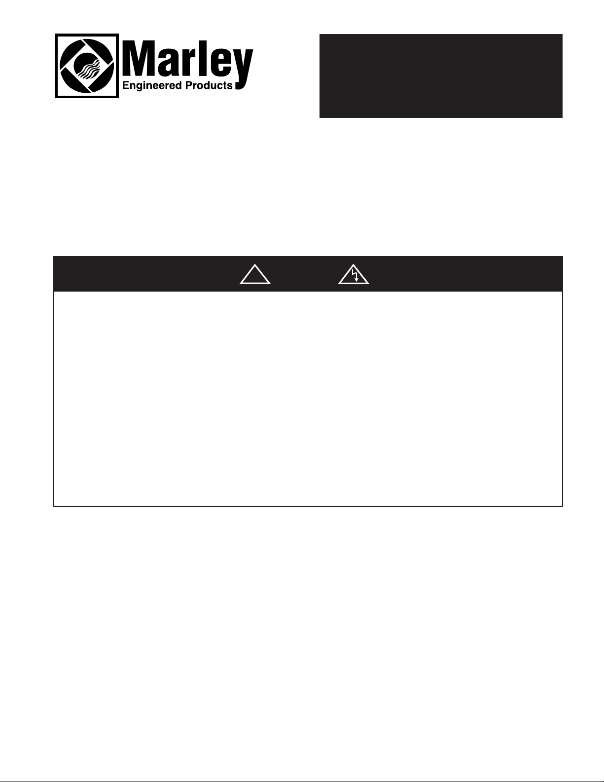
NEW HOME INSTALLATION
1. Attach duct adapter to housing by first hooking two mounting tabs
over flange in discharge opening. Pivot ductadapter insuring aligning
tabs are inside opening and align two locking tabs with small
rectangular holes. See Fig. 4. Press tabs firmly into holes to lock.
NOTE: The attachment of the duct adapter to the housing may be
reinforced if desired, by installingtwo #8AB screws through holes in
the duct adapter and the smallholes in the housing.
2. Remove grille assembly carefully and place in a safe location.
3. Before removing main unit from carton,loosen the two heater
retaining screws “A” (Fig. 1).Pull plug “P” from its receptacle.
Squeeze the heater frame to release the heater retaining bracket and
carefully lift out the heating unit until the screws disengage the
keyholes. Place in a safe location.
4. Check the ventilating section. Be sure that the motor bracket is
secured tightly to the coverplate. If not, loosen the two mounting
screws, twist the motor bracket counter-clockwise into place and
retighten the screws.
5. Next, pull the plug “R” form its receptacle, remove the retaining screw
“B” and lift out the ventilating section. Be careful not to disturb thefan
blade. Save the retaining screw.
6. Insert mounting brackets into the slots on housing, with angles
pointing away from housing. Positionhousinginto ceiling location.
Housing should extend 3/8” for drywallor 3/4” for standard sheetrock
and plaster below joist. Pull mountingbrackets against ceiling joists
and fasten securely. (Fig. 5)
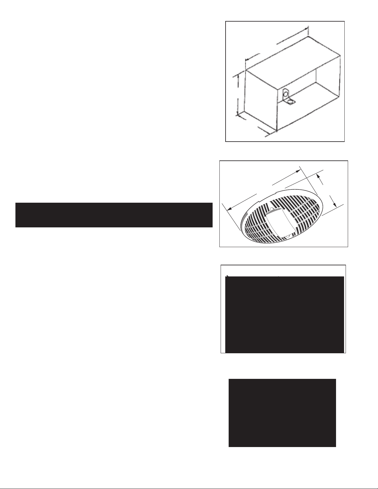
FIGURE 2
GRILLE ASSEMBLY
191/2"
FIGURE 3
DUCT ADAPTER
MOUNTING TABS
FIGURE 4
133/8"
LOCKING TABS
ALIGNING TABS
FIGURE 5
Page 3

OUTLET BOX
LIGHT
VENTILATOR
HEATER
BLACK
BLACK
WHITE
WHITE
BLACK
BLACK
GROUND
WHITE
WHITE
W
HITE
MARLEY
COMBO
SWITCH
R
ECEPTACLE
GROUND
S
CREW
120 VAC
60HZ
SUPPLY
RECEPTACLE
RECEPTACLE
OUTLET BOX
LIGHT
VENTILATOR
HEATER
WHITE
WHITE
BLACK
BLACK
BLACK BLACK
B
LACK
B
LACK
B
LACK
GROUND
WHITE
WHITE
R
ECEPTACLE
GROUND
SCREW
120V AC
60 HZ
SUPPLY
WALL
SWITCH SWITCH SWITCH
WALL WALL
RECEPTACLE
RECEPTACLE
7. Attach four inch diameter duct to duct adapter and run to roof cap or
L
IGHT
H
EATER
V
ENTILATOR
B
LACK
W
HITE
WHITE
BLUE
RED
GROUND
W
HITE
WHITE
WHITE
MARLEY
COMBO
SWITCH
RECEPTACLE
GROUND
SCREW
120 VAC
60HZ
SUPPLY
RECEPTACLE
RECEPTACLE
BROWN
YELLOW
BLACK
B
LACK
BROWN
R
ECEPTACLE
N
IGHT LIGHT
WHITE
B
LUE
OUTLET BOX
wall cap. See Figs. 6 & 7.
8. Run 120V AC, 60Hz power cables from wall switches to appropriate
knockout in housing and attach using a BX or Romex connector.
NOTE: Each mode of the unit heat/light/fan will require an individual
cable from the switch/control. Refer to the wiring diagram designated
for the model being installed.
9. Connect cables to receptacle wires in the unit using approved wire
connectors. Connect ground wire to ground (green) screw in unit.
10. Restore ventilating section to its original location. Be sure to engage
plate with tabs and fasten it with retaining screw “B”. Push plug “R” into
receptacle.
11. Restore heating unit to its original location. Tighten retaining screws
“A”. Push plug “P” into receptacle.
12. Remove lens from grille assembly by squeezing both sides. Lift grille
assembly to unit and push plug into light receptacle “S”. Engage the
long mounting screw into formed hole in cover plate. See fig. 1. Tighten
until grille is snug against ceiling.
CAUTION - Grille Assembly is intended for installation in one direction only. Plug “S” & lamp socket must be installed on same side of
fan as Light/Night Light outlet shown in Figure 1. Improper orientation
of the Grille Assembly will result in overheating of the grille and a
possible safety hazard.
FIGURE 6
4" ROUND DUCT
FIGURE 7
4" ROUND DUCT
WALL
CAP
ROOF
CAP
ROOF
13. Install 100 watt maximum type A-19 bulb and on model MM728NL a
7-1/2 watt candelabra base C-7 night light bulb. For model MM698F,
install a 13 watt twin or quad tube 2-pin compact fluorescent lamp.
Snap the lens into it’s original location.
Models:
MM698,
MM698F
Model:
MM698WC
Model:
MM728NL
INSTALLING IN EXISTING HOMES
1. Review the section: “New Home Installation” and follow instructionswhereapplicable.
2. Refer to wiringdiagram for wiringand for ductwork.
3. Drill a smallhole in proposed location,then locate this hole in the attic.
4. In theattic, position housing between ceiling joistsand over drilled hole.Usingthe housing as a template, mark ceiling
for cutout. Make cutouton this line.
5. Remainder of the installation is the same as Steps4 through9 under “New home Installation.” Cracksbetween
housing and ceiling may be plastered or caulked.
Page 4

LIMITEDWARRANTY
Dear Customer,
Thank you for your interest in Marley Engineered Products bath fans. We’re sure you will
enjoy itsbenefits formany years tocome. Pleasetake a minutetofill out the following
information and keep it in your permanent records.
Date Purchased Date Installed
Model Number Serial Number
LIMITEDWARRANTY
This Marley EngineeredProducts bath fan is warranted to be free of defects in material and
workmanship for 12 months from date of originalpurchase.
There is no other warranty,express or implied, except such as is expressly set forth herein.
Seller will not be liable for any general, consequential, or incidentaldamages, including
without limitation any damages for loss of use or loss of profits, for any breach of warranty or
for negligence. Seller’s liabilityand buyer’s exclusive remedy are limited to the repair of
defectivegoods or the shipment of equivalent goods, or the granting of a reasonable
allowanceon account of any defects, as the seller may elect.
To obtain performanceunder this warranty, you must:
1. Contact the Marley Engineered Products Service Department at 1-800-642-4328
between the hours of 9:00 a.m. and 5:00 p.m. C.S.T.Monday through Friday.
2. Provide the model number of the product, the date of installation, and state the nature of
the difficulty being experienced.
3. The Marley EngineeredProductsService Representativewill determine the best way
to resolve the difficulty.
Productswithin warranty which have been installedand returned to the seller for repair will
be repaired and returned as used products. Repairs to products outside the warranty
period will be subject to labor and parts charges.
Some states have enacted legislation which (a) does not allow the inclusion of limitations
on incidental or consequential damages; (b) does not allow limitations on the length of a
warranty period; (c) precludes exclusion, during the period of a limited warranty, of any
implied warranties of merchantability or fitness for purpose.
To the extent of such provisions being applicablein your state, the limitations in this
warrantymay not apply.
TO ENSURE SAFE OPERATION
• Be sure that this unit is correctly installed and wired by a qualified installer in accordance
with the instructionsand applicable NEC or equivalent codes.
• Be sure that operating instructions are followed and that moving parts are kept clean
and free from obstructions.
Any warranties granted or liabilities assumed hereunder will not apply to goods that have
been damaged in transit, altered,repaired, installed or operated otherwise than in
conformitywith the above requirements for safe operation.
HOW TO OBTAIN WARRANTY SERVICE AND
WARRANTY PARTS PLUS GENERAL INFORMATION
1. Warranty Service or Parts 1-800-642-4328
2. Purchase Replacement Parts 1-800-654-3545
3. General Product Information www.marleymep.com
Note: When obtaining service always have the following:
1. Model number of the product
2. Date of manufacture
3. Part number or description
Part No.5200-2501-002 ECR 37434
8/07
470 Beauty Spot Rd. East
Bennettsville, SC 29512 USA
 Loading...