

Page 1
MODEL
A647B &
MM647B FANS
“READ AND SAVE THESE INSTRUCTIONS”
Models A647B, and MM647B fan are intended for use in bathrooms. However, they can
also be used in other areas where ventilation is required other than kitchens. These mod-
els may be installed in a side wall or a cathedral ceiling if a 3-
7
⁄8” minimum space is avail-
able. When used in a side wall install the fan at least 5 feet (1.5m) above the floor.
UNPACKING
Unpack carefully. If there are missing components or hidden damage immediately
contact
your distributor or the delivering carrier concerning discrepancies.
IMPORTANT SAFETY INSTRUCTIONS
WARNING:
TO REDUCE THE RISK OF FIRE, ELECTRICAL SHOCK OR
INJURY TO PERSONS, OBSERVE THE FOLLOWING:
1. Do not use this fan with any Solid-State speed control device.
2. Use this unit only in the manner intended by the manufacturer. If you have
questions, contact the manufacturer.
3. Before servicing or cleaning unit, switch power off at service panel and lock
service panel to prevent power from being switched on accidentally.
4. Installation work and electrical wiring must be done by qualified person(s) in
accordance with all applicable codes and standards, including fire-rated
construction.
5. Sufficient air is needed for proper combustion and exhausting of gases
through the flue (chimney) of fuel burning equipment to prevent back drafting.
Follow the heating equipment manufacturer’s guideline and safety standards
such as those published by the National Fire Protection Association (NFPA),
and the American Society for Heating Refrigeration and Air Conditioning
Engineers (ASHRAE), and the local code authorities.
6. When cutting or drilling into wall or ceiling, do not damage electrical wiring or
other hidden utilities.
7. Ducted fans must always be vented to the outdoors.
8. If this unit is installed over a tub or shower, it must be marked as appropriate
for the application. See product label.
9. NEVER place a switch where it can be reached from a tub or shower.
10. CAUTION: For General Ventilating Use Only! Do not use to exhaust hazardous
or
explosive materials and vapors.
11. Not for use in kitchens.
LIMITED WARRANTY
Dear Customer,
Thank you for your interest in Marley Engineered Products products. We’re sure you will enjoy its benefits for
many years to come. Please take a minute to fill out the following information and keep it in your permanent
records.
Date Purchased Date Installed
Model Number Serial Number
LIMITED WARRANTY
This Marley Engineered Products product is warranted to be free of defects in material and workmanship for
12 months from date of original purchase.
Elements for baseboard heaters are warranted for 10 years from the date of original purchase.
There is no other warranty, express or implied, except such as is expressly set forth herein. Seller will not
be liable for any general, consequential, or incidental damages, including without limitation any damages
for loss of use or loss of profits, for any breach of warranty or for negligence. Seller’s liability and buyer’s
exclusive remedy are limited to the repair of defective goods or the shipment of equivalent goods, or the
granting of a reasonable allowance on account of any defects, as the seller may elect.
To obtain performance under this warranty, you must:
1. Contact the Marley Engineered Products Service Department at 1-800-642-HEAT between the
hours of 8:30 a.m. and 5:00 p.m. E.S.T. Monday through Friday.
2. Provide the model number of the product, the date of installation, and state the nature of the difficulty
being experienced.
3. The Marley Engineered Products Service Representative will determine the best way to resolve the
difficulty.
Products within warranty which have been installed and returned to the seller for repair will be repaired and
returned as used products. Repairs to products outside the warranty period will be subject to labor and
parts charges.
Some states have enacted legislation which (a) does not allow the inclusion of limitations on incidental or
consequential damages; (b) does not allow limitations on the length of a warranty period; (c) precludes exclu-
sion, during the period of a limited warranty, of any implied warranties of merchantability or fitness for pur-
pose.
To the extent of such provisions being applicable in your state, the limitations in this warranty may not apply.
TO ENSURE SAFE OPERATION
• Be sure that this unit is correctly installed and wired by a qualified installer in accordance with the instruc-
tions and applicable NEC or equivalent codes.
• Be sure that operating instructions are followed and that moving and heating parts are kept clean and
free from obstructions.
Any warranties granted or liabilities assumed hereunder will not apply to goods that have been damaged
in transit, altered, repaired, installed or operated otherwise than in conformity with the above requirements for
safe operation.
Part No. 5200-2518-004
8/06
HOW TO ORDER REPAIR PARTS
In order to obtain any needed repair or replacement
parts, warranty service or technical information, please
contact Marley Engineered Products Service Center toll-
free by calling 1-800-642-HEAT.
When ordering repair parts, always give the informa-
tion listed as follows:
1. The Part Number
2. The Model Number
3. The Part Description
4. Date of Manufacture
470 Beauty Spot Rd. East
Bennettsville, SC 29512 USA
Page 2
NEW HOME INSTALLATION
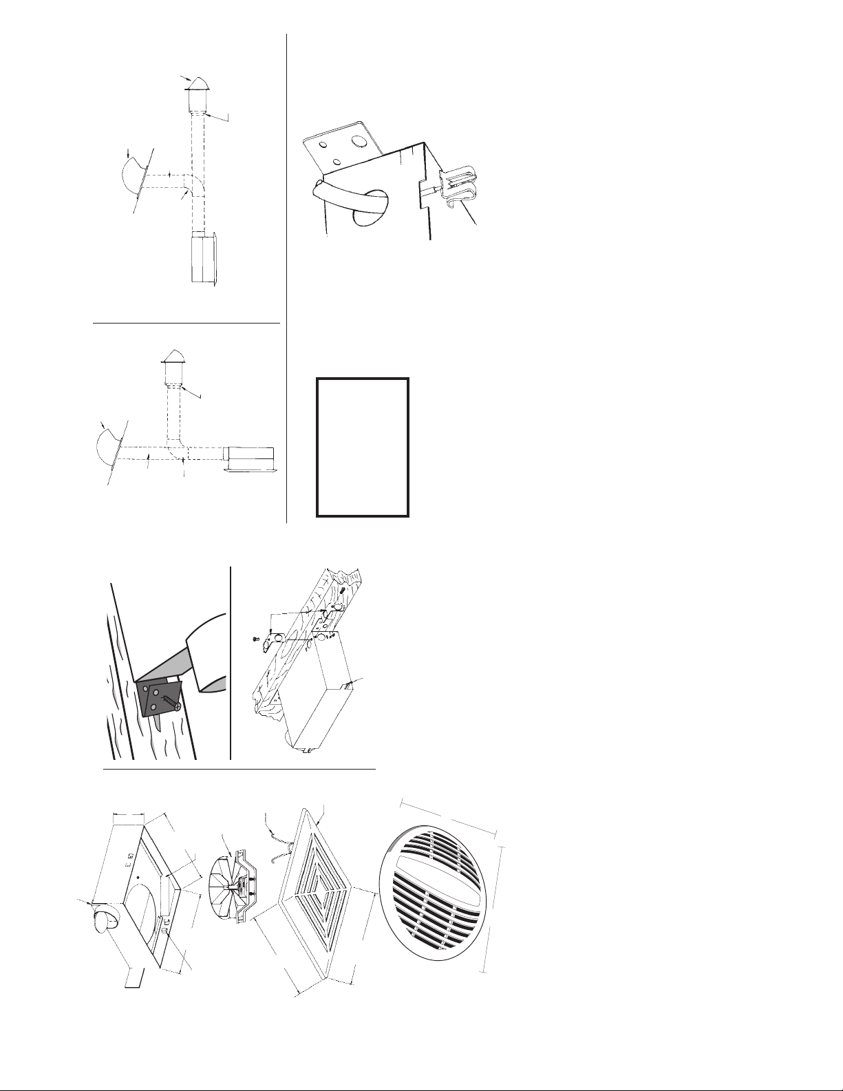
1. Carefully remove unit from carton. Place grille in a safe location until needed. Remove ship-
ping tape from air discharge backdraft damper.
2. Position housing against joist. Housing is stamped to show a line at 3/4” for standard
sheetrock and plaster and 3/8” for drywall. (See Figs. 2 & 3). Drive pre-assembled screws on
mounting brackets to secure housing. There are two tabs opposite each mounting bracket to
provide additional support. If the unit is mounted for 3/8” clearance, the small tab remains in
place. If mounted for 3/4” clearance, the smaller tab is bent out of the way to expose the larger
box.
3. Run 120VAC, 60Hz power leads from wall switch or Model 1011 timer to appropriate knockout
in housing. Use a BX of Romex connector on outlet box.
4. Remove outlet box cover by pulling downward while simultaneously pushing in side of cover
at indicated point to release locking tab. Connect wire from wall switch to motor wire using
approved wire connectors - white to white, black to black. Remove grounding clip and insert
ground wire. (See Fig. 6) Push or tap clip into notch in housing. Cut off excess ground wire.
Replace outlet box cover insuring locking tab is engaged.
-2-
5. Run three-inch round duct from ventilator air discharge outlet to wall or roof cap . (See Fig. 4 &
5.)
IMPORTANT: BE SURE NOTHING OBSTRUCTS THE DISCHARGE OF THE FAN. TAKE
PRECAUTIONS TO ENSURE THAT INSULATION DOES NOT GET INTO THE DUCT WORK
OR FAN DISCHARGE OPENING.
6. Install grille by Squeezing springs and inserting into tabs located in housing. See Fig. 1. Press grille
firmly inplace.
INSTALLATION IN EXISTING HOMES
1. Review “New Home Installation” above and follow all instructions where applicable.
2. Refer to Fig. 4 & 5 for duct work.
3. Determine proposed location of fan, remembering that the housing must be installed next
to joist.
4. Drill a small hole in ceiling in proposed location, then locate this hole in the attic.
5. In the attic, position housing against ceiling joist and over drilled hole. Using the housing as
a template mark ceiling for cutout. Make cutout on this outline.
6. Remainder of the installation is the same as steps 1 thru 6 under “New Home Installation”
above. Any cracks between housing and ceiling may be plastered or caulked.
CAUTION
Be sure all wiring
complies with Local and
National Electrical Codes
and housing is properly
grounded.
FIG. 1
FIG. 2
FIG. 3
FIG. 4 FIG. 5
FIG. 6
AIR DISCHARGE
OUTLET
KNOCKOUT
SUPPORT
MOUNTING
TABS
3” ROUND
DUCT
3” ROUND DUCT
ADJUSTABLE
ELBOW
ADJUSTABLE
ELBOW
MODEL 1117A
WALL
CAP
MODEL 1117A WALL CAP
IN WALL
IN CEILING
MODEL AD1106 ROOF CAP
MODEL AD1106 ROOF CAP
REDUCER FURNISHED
WITH WALL CAP
REDUCER FURNISHED
WITH WALL CAP
OUTLET BOX
MOTOR &
BRACKET
ASSEMBLY
SPRING CLIP
GRILLE
8
5
⁄8”
9
5
⁄8”
6
13
⁄16”
7
13
⁄16”
GRILL
MTG TABS
3
3
⁄4”
3
⁄4
3
⁄8
12
1
⁄4”
10
3
⁄4”
MM647B
A647B
Note: Duct adapter may be installed at factory.
Remove tape from duct door before use.
DUCT
ADAPTER
 Loading...