

Page 1
MCARWH Series
Mechanical Artisan
Heavy-Duty Architectural
Wall Heater
Installation, Operation & Maintenance Instructions
Table 1. Specifications
MIN. SUPPLY
MODEL VOLTS PHASE WATTS AMPS WIRE GAUGE
MCARWH1802 120 1 1800 15 12
MCARWH4808 208 1 4000 / 2000 19.2 / 9.6 10
MCARWH4804 240 1 4800 / 2400 20.0 / 10.0 10
MCARWH4807 277 1 4800 / 2400 17.3 / 8.7 12
NOTE: The model numbers shown are Northern White color. Add suffix to the model number for the following colors:
AL = Aluminum, BZ = Bronze, W = Navajo White.
IMPORTANT INSTRUCTIONS
WARNING
WHEN USING ELECTRIC APPLIANCES, BASIC PRECAUTIONS SHOULD ALWAYS BE FOLLOWED TO REDUCE THE
RISK OF FIRE, ELECTRIC SHOCK, AND INJURY TO PERSONS, INCLUDING THE FOLLOWING:
1. Read all instructions before installing or using this heater.
2. This heater is hot when in use. To avoid burns, do not let
bare skin touch hot surfaces. Keep combustible materials,
such as furniture, pillows, bedding, papers, clothes, etc. and
curtains at least 3 feet (0.9 m) from the front of the heater.
3. Extreme caution is necessary when any heater is used by or
near children or invalids and whenever the heater is left
operating and unattended.
4. Do not operate any heater after it malfunctions. Disconnect
power at service panel and have heater inspected by a reputable electrician before using.
5. Do not use outdoors.
6. To disconnect heater, turn controls to OFF, and turn OFF
power to heater circuit at main disconnect panel.
7. Do not insert or allow foreign objects to enter any ventilation
or exhaust opening as this may cause an electric shock, fire,
or damage to the heater.
8. To prevent a possible fire, do not block air intake or exhaust
in any manner.
!
9. A heater has hot and arcing or sparking parts inside. Do not
use it in areas where gasoline, paint, or flammable liquids
are used or stored.
10. Use this heater only as described in this manual. Any other
use not recommended by the manufacturer may cause fire,
electric shock, or injury to persons.
11. This heater is provided with a red alarm light that will illuminate only if the heater has turned off as a result of overheating. Should the sensor register an overheat condition,
the heater will stop generating heat, the fan will turn off, and
the red alarm light will turn ON. DO NOT OPERATE THE
HEATER WITH THE ALARM LIGHT ILLUMINATED. See
“TO RESET MANUAL RESET LIMIT” in OPERATING
INSTRUCTION section.
12. This heater is intended for comfort heating applications and
not intended for use in special environments. Do not use in
damp or wet locations such as marine or greenhouse or in
areas where corrosive or chemical agents are present.
13. When installing, see INSTALLATION INSTRUCTIONS for
additional warnings and precautions.
14. For safe and efficient operation, and to extend the life of your
heater, keep your heater clean - See MAINTENANCE
INSTRUCTIONS.
SAVE THESE INSTRUCTIONS
PPD 39696 4/14 5200-11204-000
Page 2
INSTALLATION
INSTRUCTIONS
To prevent a possible fire, injury to persons or damage to the
heater, adhere to the following:
1. Disconnect all power coming to heater at main service
panel before wiring or servicing.
2. All wiring procedures and connections must be in accordance with the National and Local Codes having jurisdiction
and the heater must be grounded.
3. Verify the power supply voltage coming to heater matches
the ratings as shown on the heater nameplate.
CAUTION: ENERGIZING HEATER AT A VOLTAGE GREATER
THAN THE VOLTAGE PRINTED ON THE NAMEPLATE WILL
DAMAGE THE HEATER AND VOID THE WARRANTY AND
COULD CAUSE A FIRE.
4. CAUTION - High temperature, risk of fire, keep electrical
cords, drapery, furnishings, and other combustibles at least
3 feet (0.9 m) from front of heater. Do not install heater
behind doors, below towel racks, or in an area where it is
subject to being blocked by furniture, curtains or storage
materials. Hot air from the heater may damage certain fabrics and plastics.
5. To reduce the risk of fire, do not store or use gasoline or
other flammable vapors and liquids in the vicinity of the
heater.
6. For wall mounting only with air discharge downward. Do
NOT install in floor, ceiling, upside down (air discharge
upward), or sideways.
7. The following minimum clearances must be maintained:
Bottom of heater to floor - 12” (305 mm).
Sides of heater to adjacent wall - 12” (305 mm).
Top of heater to ceiling - 36” (915 mm).
8. Do not operate the heater without the back box.
9. Do not use this heater for dry out purposes as the paint,
plaster, sawdust and drywall sanding dust will permanently
damage the heater and must be kept out of the heater.
10. Remove motor shipping bracket and yellow tag prior to operating this heater.
The heater is designed for recessed installation in 2” x 4”
(50 mm x 101 mm) studs or larger wall sections using the back
box provided. The heater may be wired with standard building
wire (60°C). Refer to “Specifications” and heater nameplate for
correct supply voltage and wire size.
NOTE: The optimum mounting height for this heater is 18” to 24”
(450 mm to 600 mm) from floor to bottom of back box. DO NOT
install closer than 12” (305 mm) from the floor.
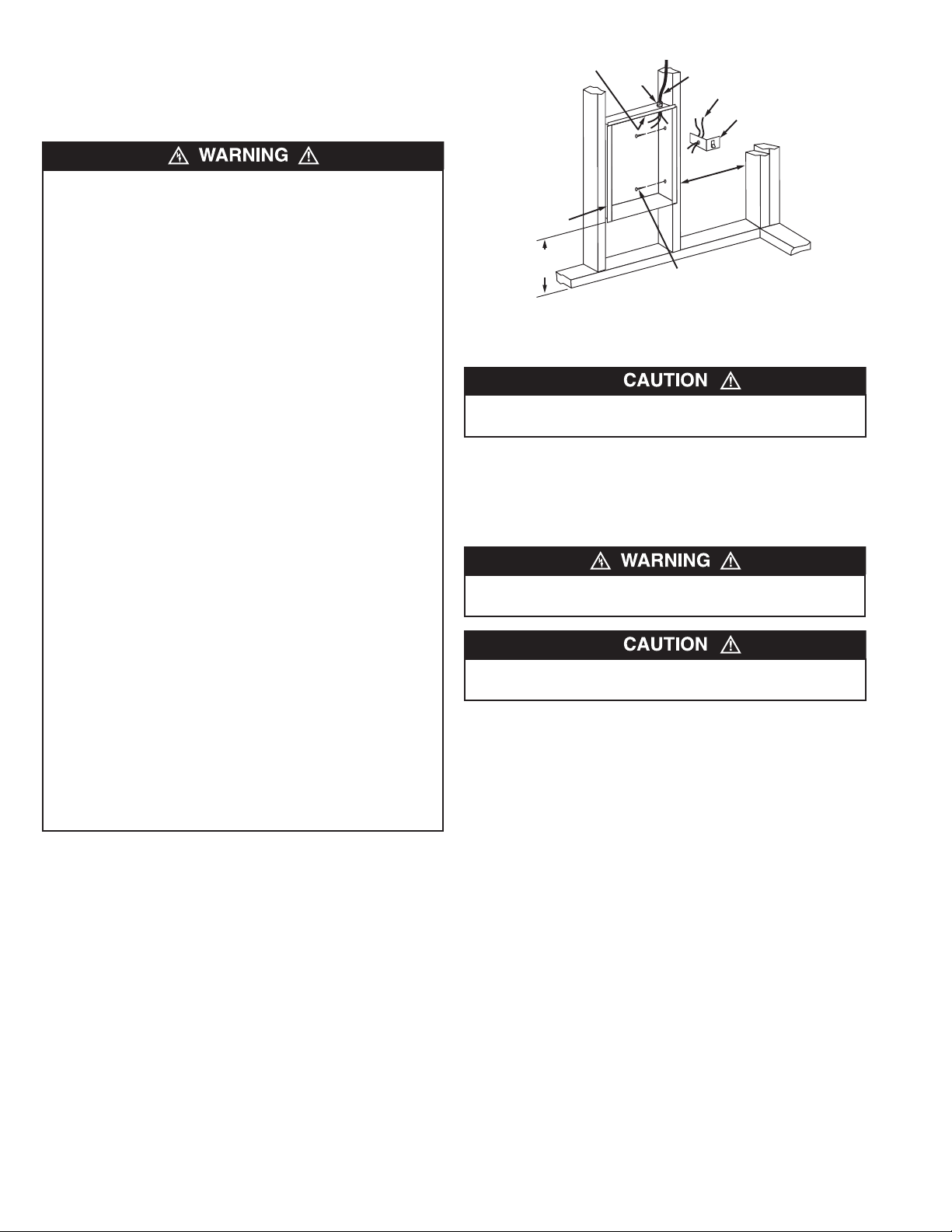
Ground screw
Back Box
12” Min.
(305 mm)
Figure 1: Locating Back Box in New Construction
Cable
clamp
Power supply cable
Lead wires (Blue)
12” Min.
(305 mm)
Nail or screw
(2 each side)
Disconnect switch
bracket with switch and
leads
(No disconnect
switch on
208V models)
Mounting Clearances
TO PROVIDE FOR SAFE OPERATION, THE FOLLOWING
CLEARANCES MUST BE MAINTAINED.
Wall Mounting Only:
a. Minimum twelve (12) inches (305 mm) to floor;
b. Minimum twelve (12) inches (305 mm) to adjacent walls;
c. Minimum thirty six (36) inches (915 mm) to ceiling.
TO PREVENT HAZARD OF FIRE OR ELECTRICAL SHOCK,
DO NOT INSTALL WITHOUT BACK BOX.
TO PREVENT POSSIBLE DAMAGE TO POWER WIRING,
USE ONLY THE KNOCKOUTS PROVIDED IN BACK BOX.
Installation of Back Box in New Construction
(See Figure 1).
NOTE: If the finished wall surface is already up, follow instruc-
tions for “Installation of Back Box in Existing Construction”.
1. Place the back box between two 16" (406 mm) center-tocenter wall studs at the desired mounting height but no closer than 12" (305 mm) to adjacent wall or floor.
NOTE: If wall studs are spaced greater than 16” (407 mm) on
center, additional framing supports may be necessary.
2. Align back box such that the bottom and sides will be flush
with finished wall surface (top flange of back box should protrude approximately 1/2" (12.7 mm) from finished wall surface
(You must know the thickness of the finished wall when
installing).
3. Secure the back box in position with wood screws or nails as
shown in Figure 1.
4. Run a power supply cable into the knockout area in the upper
right hand corner of the back box (see Figure 1). All wiring
must be in accordance with National and Local Electrical
Codes. Refer to Specifications for correct wire size.
5. Remove disconnect switch bracket by loosening two screws
on the right side.
6. Install a cable clamp in the knockout in the top of the back
box.
2
Page 3
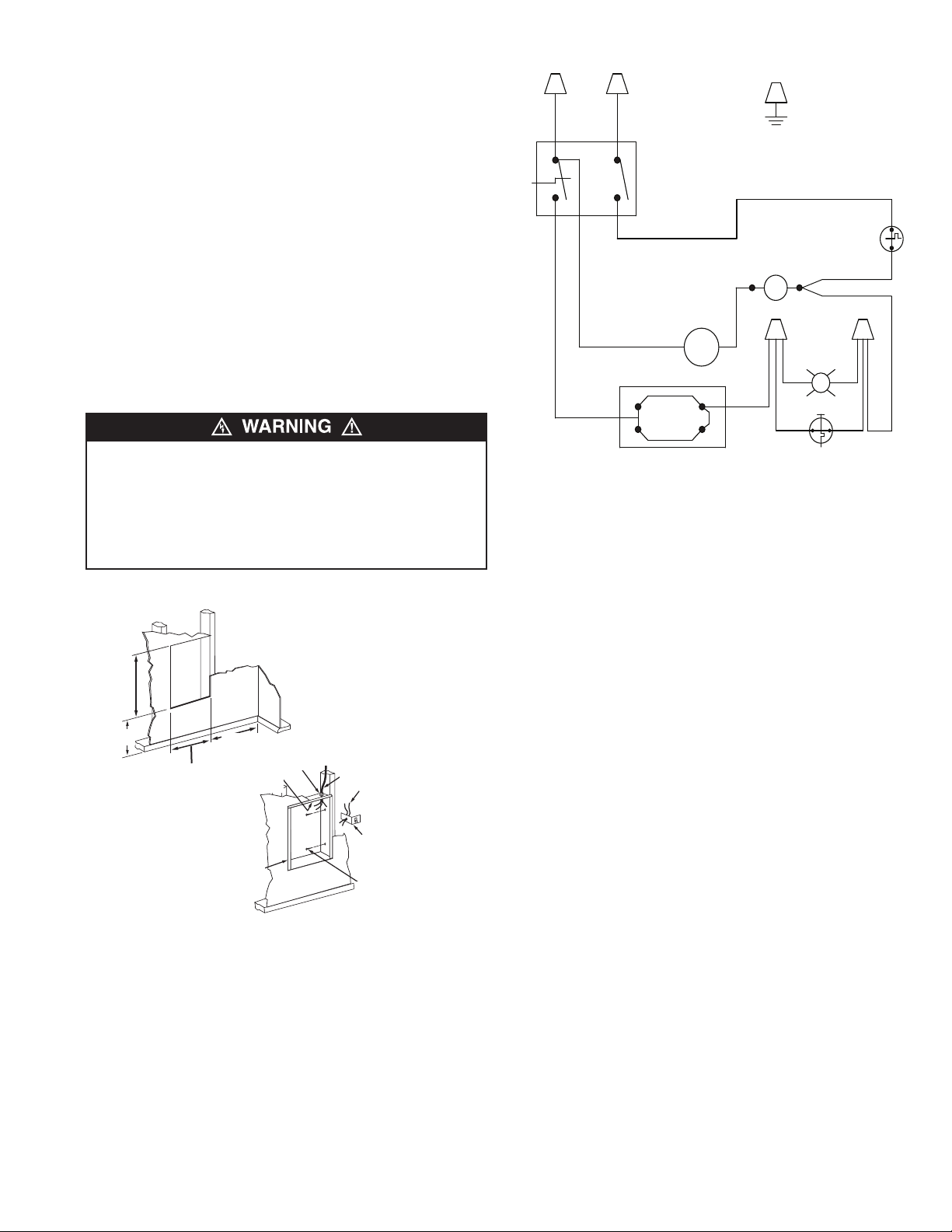
GND
TO
DISCONNECT
SWITCH
L1
L2
PL
F.D
THERMOSTAT
L1
OFF
L2
CYC
MOTOR
MOTOR
E1
E2
JUMPER
BLK
MANUAL RESET
LIMIT
EOL
ELEMENTS
MOTOR
7. Insert power supply cable through cable clamp, allowing at
least 6" (152 mm) of leads to extend inside the back box.
Connect the blue lead wires of disconnect switch to the supply wire leads using wire connectors (see Figure 3, Wiring
Diagram).
NOTE: If power supply is provided by standard non-metallic
sheathed cable (Romex) and the supply voltage is 240 or 208
volts (two power wires), the white wire color must be changed
using black electrical tape to comply with the NEC. White is only
allowed for a Neutral conductor.
8. Connect building ground conductor to the back box using the
green pigtail lead located in the inside top of the back box
and secure second green pigtail lead to back box green pigtail.
9. Feed remaining 2 wires from disconnect switch through hole
in switch bracket and secure disconnect switch bracket in
place by tightening screws.
10. Secure disconnect switch bracket in place by tightening
screws.
POWER SUPPLY VOLTAGE MUST BE THE SAME AS
HEATER VOLTAGE RATING SHOWN ON HEATER NAMEPLATE. CONNECTING TO A VOLTAGE IN EXCESS OF
Figure 3: Wiring Diagram
NAMEPLATE RATING WILL DAMAGE HEATER AND VOID
WARRANTY.
ALL CONNECTIONS MUST BE MADE WITH APPROPRIATELY
SIZED LISTED WIRE CONNECTORS.
Installation of Recessed Back Box in
Existing Construction
1. Provide a wall opening 14-3/4" (375 mm) wide by 18-1/2"
(470 mm) high at the desired mounting height, but no closer
than 12" (305 mm) from floor. (See Figure 2.) Locate so at
least one side of opening is at wall stud.
2. Run a power supply cable into the knockout area in the upper
right hand corner of the wall opening (see Figure 2). All
wiring must be in accordance with National and Local
Electrical Codes. Refer to Specifications for correct wire size.
3. Remove disconnect switch bracket by loosening two screws
on the right side.
12” Min.
(305 mm)
Figure 2: Locating Back Box in Existing Construction
14 1/2” Min.
(362 mm)
12” Min.
(305 mm)
Back Box
Ground
screw
Cable
clamp
Power supply cable
Lead wires (Blue)
Disconnect switch
bracket with switch
and leads. (No disconnect switch on 208V
models)
Nail or screw
(2 each side)
4. Install a cable clamp in the knockout in the top of the back
box.
5. Insert power supply cable through cable clamp, allowing at
least 6" (152 mm) of leads to extend inside the back box.
Connect the blue lead wires of disconnect switch to the supply wire leads using wire connectors (see Figure 4, Wiring
Diagram).
NOTE: If power supply is provided by standard non-metallic
sheathed cable (Romex) and the supply voltage is 240 or 208
volts (two power wires), the white wire color must be changed
using black electrical tape to comply with the NEC. White is only
allowed for a Neutral conductor.
6. Connect building ground conductor to the back box using the
green screw located in the inside top of the back box.
9. Feed remaining 2 wires from disconnect switch through hole
in switch bracket and secure disconnect switch bracket in
place by tightening screws.
8. Insert back box in wall opening being careful not to damage
the supply wiring. Secure the back box in place with wood
screws or nails.
3
Page 4

Building Management Systems (BMS)
To utilize BMS capabilities of this unit, there are two (optional)
accessories available. Model WHR2A which has a 24 volt holding coil can switch the heaters ON/OFF from remote source.
Model WHR12A which has a 120 volt holing coil can switch the
heaters ON/OFF from remote source.
Refer to the control installation manual when installing.
Installation of Back Box with Optional
Surface-Mounting Frame HTWHSM (See Figure 4)
1. Secure back box to wall with knockouts in upper right hand
corner using screws and anchors.
2. Hang the surface-mounting frame on the back box. Ensure
that the back edge of the surface-mounting frame is flush
against the wall.
NOTE: If heater is located in a high traffic area, where it may be
subjected to vandalism or abuse, take extreme care to see that
the back box is firmly attached to the wall.
3. Power Supply Wiring
NOTE: Wiring Compartment Volume - 119in3 (1950cm3).
a. Run a power supply cable into the area to the right of the
mounting frame. Arrangement of wiring to this point must
be in accordance with National and Local codes. Refer to
Table 1 on page 1 for proper wire size.
MOUNT BACK BOX
TO WALL USING
REAR MOUNTING
HOLES.
HANG FRAME
ON BACK BOX.
15-5/32 "
Figure 4 - Surface Mounting Installation
(385mm)
NOTE: If the wiring is to run through the wall, cut a hole I in the
area of the top right corner of the back box. Run the supply wire
through this hole. Then remove the “knockout” from the top of the
box and proceed to step C.
c. Remove disconnect switch bracket by loosening the two
screws on the right side.
d. Feed the power supply cable through the frame allowing
6in (152mm) of lead to remain inside the back box (using a
cable clamp, connector, or other suitable strain relief)
e. Secure the power supply cable to the back box (using
cable clamp, connector, or other suitable strain relief)
allowing 6in (152mm) of lead to remain inside the back
box.
f. Connect supply wires to blue wires of disconnect switch
using wiring connectors (see wiring diagram 3, Page 3).
g. Ground the back box by connecting the supply ground
lead wire to the green ground screw located in the inside
top of the back box.
h. Feed remaining 2 wires from disconnect switch through
hole in the switch bracket and secure disconnect switch
bracket in place.
3-13/16"
(97mm)
19"
(482mm)
Installation of Heater / Grille into Back Box
Note to Installer: Converting heater to half wattage
(Not applicable to MCARWH1802 120 Volt Models)
The MCARWH Series wall heaters are manufactured and
shipped at the higher rated wattage. Full wattage heaters can be
converted to half wattage by doing the following steps.
1. Remove the red jumper wire as shown in Figure 5 and discard.
2. To permanently make the heater half wattage, cut the male
terminal spade, carefully not to damage the cold pin and discard.
3. Mark the wattage of the heater on the white label inside the
back box.
After back box is completely installed and no further construction
dirt is expected, clean debris from back box and remove heater
assembly from its carton.
1. Lift and rotate the grille assembly into the back box carefully
to ensure the wiring is not trapped between the grille assembly and back box. Position the grille assembly in front of the
back box and insert Control Shelf into the notches on either
side of the back box. At the same time hooking the tabs on
the bottom corners of the grille assembly over the bottom
flange of the back box. Refer to figures 6 and 7..
2. With the top of the grille assembly leaning forward, supported
by the first notch in control shelf, extend the lead wires from
the back of the top of the heater grille assembly to the (2)
power wires of the disconnect switch assembly and connect
according to Wiring Diagram shown in Figure 3 (page 3)
3. If a surface mounting frame is used, ensure that the frame is
even with all four sides of the heater.
4. Connect the two disconnected switch wires to the heater
wires using wire nuts (provided). After the connection, carefully push wires back into the opening.
5. Turn thermostat to the extreme counterclockwise position in
OFF position.
6. Push disconnect switch to ON position.
7. Tighten top cover screws down to hold grille in place.
See Figure 8.
THE HEATER ASSEMBLY MUST BE CAREFULLY POSITIONED TO ENSURE THE CONTROL WIRES ARE NOT
TRAPPED BETWEEN THE HEATER ASSEMBLY AND THE
BACK BOX.
Male terminal spade
Red jumper wire
Figure 5- Jumper Wire Location
4
Page 5

Control
Shelf
Figure 6- Installation of Heater/Grille Assembly
Back Box
Notch
Tab
Notches
OPERATION
INSTRUCTIONS
1. Heater must be properly installed before operation.
2. Turn power supply ON at the service panel for this heater.
3. Rotate the thermostat fully clockwise. This should energize
the heating elements and cause warm air to flow from the hot
air discharge at the openings in the bottom front part of the
grille. This may take a minute or two for the fan delay to operate the fan.
4. After the operation check, rotate the thermostat counterclockwise to the desired position to obtain room comfort.
Note: For best results, the heater should be left “ON” constantly
during the heating season because the thermostat, when
properly set, will maintain the desired temperature.
THE ACTIVATION OF THE THERMAL LIMIT CONTROL AND
RED WARNING LIGHT OCCURS IF THE HEATER OVERHEATS. CHECK HEATER TO MAKE SURE IT IS NOT
BLOCKED – IF SO, REMOVE THE BLOCKAGE. IF THERE IS
NO BLOCKAGE, IT IS RECOMMENDED THAT THE HEATER
BE INSPECTED BY A REPUTABLE ELECTRICIAN OR
REPAIR SERVICE TO ENSURE THE HEATER IS NOT
DAMAGED. DO NOT CONTINUE TO USE HEATER IF IT
REPEATEDLY CYCLES OFF ON THIS THERMAL LIMIT.
Control
Shelf
Figure 7- Heater / Grille Assembly Detail, Grille Supported for Wiring
Figure 8- Securing Bezel
Flange
TO RESET THERMAL LIMIT CONTROL
Your heater is equipped with a manual reset safety thermal limit
control that will automatically turn the heater OFF to prevent a
fire if the heater overheats. This control is mounted inside the
heater (top left). On the top cover of the grille assembly it is
marked “Reset Button.” REMOVE the plug button that covers the
hole. To reset, allow the heater to cool, then push the red button
that is visible through the hole downward (you may have to use
a pencil- blunt side) to reach the button. The heater should
immediately return to normal operation.
DO NOT TAMPER WITH OR BYPASS ANY THERMAL LIMITS
INSIDE HEATER.
NOTE: The unit is provided with an End of Life “oneshot” protective device. This serves as a back up protector in extreme conditions if the overheat protector fails to maintain safe temperatures
during an overheat condition. If the end of life control activates,
the heater must be checked by a reputable repairman.
Figure 9- Top Panel Layout
5
Page 6

MAINTENANCE
INSTRUCTIONS
It is important to keep this heater clean. Your heater will give you
years of service and comfort with only minimum care. To assure
efficient operation follow the simple instructions below.
ALL SERVICING BEYOND SIMPLE CLEANING THAT
REQUIRES DISASSEMBLY SHOULD BE PERFORMED BY
QUALIFIED SERVICE PERSONNEL.
TO REDUCE RISK OF FIRE AND ELECTRIC SHOCK OR
INJURY, DISCONNECT ALL POWER COMING TO HEATER
AT MAIN SERVICE PANEL AND CHECK THAT THE ELEMENT
IS COOL BEFORE SERVICING OR PERFORMING
MAINTENANCE.
User Cleaning Instructions:
1. After the heater has cooled, a vacuum cleaner with brush
attachment may be used to remove dust and lint from exterior
surfaces of the heater including the grille openings.
2. With a damp cloth, wipe dust and lint from grille and exterior
surfaces.
3. Return power to heater and check to make sure it is operating properly.
Maintenance Cleaning Instructions:
(To be performed only by Qualified Service Personnel)
At least annually, the heater should be cleaned and serviced by
a qualified service person to assure safe and efficient operation.
This should include the removal of the heater grille assembly
from the back box to clean residue from the unit. After completing the cleaning and servicing, the heater should be fully
reassembled and checked for proper operation.
6
Page 7

REPAIR PARTS
16
12
11
4
10
13
8
9
7
6
3
15
17
1
5
14
2
Repair Parts List
Ref Part Number
No Description MCARWH4804 MCARWH4808 MCARWH4807 MCARWH1802
1 Grille 2501-11023-VAR* 2501-11023-VAR* 2501-11023-VAR* 2501-11023-VAR*
2 Cover Bracket Lower Left 1215-11070-000 1215-11070-000 1215-11070-000 1215-11070-000
3 Cover Bracket Lower Left 1215-11070-001 1215-11070-001 1215-11070-001 1215-11070-001
4 Motor Mount Bracket 1215-2235-002 1215-2235-002 1215-2235-002 1215-2235-002
5 Fan Blade 490030103 490030103 490030103 490030103
6 Thermal Cutout 4520-2030-000 4520-2030-000 4520-2030-000 4520-2030-000
7 Element Retention Bracket 1215-11090-000 1215-11090-000 1215-11090-000 1215-11090-000
8 Fan Delay 410074000 410074000 410074000 1414-2039-000
9 Clip-limit Capillary 402040001 402040001 402040001 402040001
10 Bracket - Limit 1215-11101-000 1215-11101-000 1215-11101-000 1215-11101-000
11 Protect or Manual Reset 4520-11019-000 4520-11019-000 4520-11019-000 4520-11019-000
12 Thermostat 2-Pole 5813-2027-000 5813-2027-000 5813-2027-000 5813-2027-000
13 Motor 3900-2010-000 3900-2010-000 3900-2010-001 3900-2010-003
14 Element 302012810 302012807 302012811 302012828
15 Bezel 4503-11015-000 4503-11015-000 4503-11015-000 4503-11015-000
16 Control Knob 3301-11013-000 3301-11013-000 3301-11013-000 3301-11013-000
17. Light (Alarm) 3510-2010-000 3510-2010-000 3510-2010-000 3510-2010-000
*NOTE: The standard color is Northern White. Add suffix to the model number for the following colors:
AL = Aluminum, BZ = Bronze, W = Navajo White. Call Factory for part number.
7
Page 8

All products manufactured by Marley Engineered Products are warranted against defects in workmanship and materials for one year from date of installation, except
LIMITED WARRANTY
heating elements which are warranted against defects in workmanship and materials for five years from date of installation. This warranty does not apply to damage from
accident, misuse, or alteration; nor where the connected voltage is more than 5% above the nameplate voltage; nor to equipment improperly installed or wired or
maintained in violation of the product’s installation instructions. All claims for warranty work must be accompanied by proof of the date of installation.
The customer shall be responsible for all costs incurred in the removal or reinstallation of products, including labor costs, and shipping costs incurred to return products to
Marley Engineered Products Service Center. Within the limitations of this warranty, inoperative units should be returned to the nearest Marley authorized service center
or the Marley Engineered Products Service Center, and we will repair or replace, at our option, at no charge to you with return freight paid by Marley. It is agreed that such
repair or replacement is the exclusive remedy available from Marley Engineered Products.
THE ABOVE WARRANTIES ARE IN LIEU OF ALL OTHER WARRANTIES EXPRESSED OR IMPLIED, AND ALL IMPLIED WARRANTIES OF MERCHANTABILITY AND
FITNESS FOR A PARTICULAR PURPOSE WHICH EXCEED THE AFORESAID EXPRESSED WARRANTIES ARE HEREBY DISCLAIMED AND EXCLUDED FROM THIS
AGREEMENT. MARLEY ENGINEERED PRODUCTS SHALL NOT BE LIABLE FOR CONSEQUENTIAL DAMAGES ARISING WITH RESPECT TO THE
PRODUCT, WHETHER BASED UPON NEGLIGENCE, TORT, STRICT LIABILITY, OR CONTRACT.
Some states do not allow the exclusion or limitation of incidental or consequential damages, so the above exclusion or limitation may not apply to you. This warranty gives
you specific legal rights, and you may also have other rights which vary from state to state.
For the address of your nearest authorized service center, contact Marley Engineered Products in Bennettsville, SC, at 1-800-642-4328. Merchandise returned to the factory must be accompanied by a return authorization and service identification tag, both available from Marley Engineered Products. When requesting return authorization,
include all catalog numbers shown on the products.
HOW TO OBTAIN WARRANTY SERVICE AND
WARRANTY PARTS PLUS GENERAL INFORMATION
1. Warranty Service or Parts 1-800-642-4328
2. Purchase Replacement Parts 1-800-654-3545
3. General Product Information www.marleymep.com
Note: When obtaining service always have the following:
1. Model number of the product
2. Date of manufacture
3. Part number or description
Note: Do not return to manufacturer.
470 Beauty Spot Rd. East
Bennettsville, SC 29512 USA
 Loading...