

Page 1
AIR CIRCULATOR ASSEMBLY AND
INSTALLATION INSTRUCTIONS
OSCILLATING AIR CIRCULATOR
MODEL: LCHHD24-O AND LCHHD30-O
READ INSTRUCTIONS CAREFULLY BEFORE ATTEMPTING TO ASSEMBLE, OPERATE OR MAINTAIN THE PRODUCT DESCRIBED. PROTECT YOURSELF AND OTHERS BY OBSERVING ALL SAFETY INFORMATION. FAILURE
TO COMPLY WITH INSTRUCTIONS COULD RESULT IN PERSONAL INJURY AND/OR PROPERTY DAMAGE.
RETAIN INSTRUCTIONS FOR FUTURE REFERENCE.
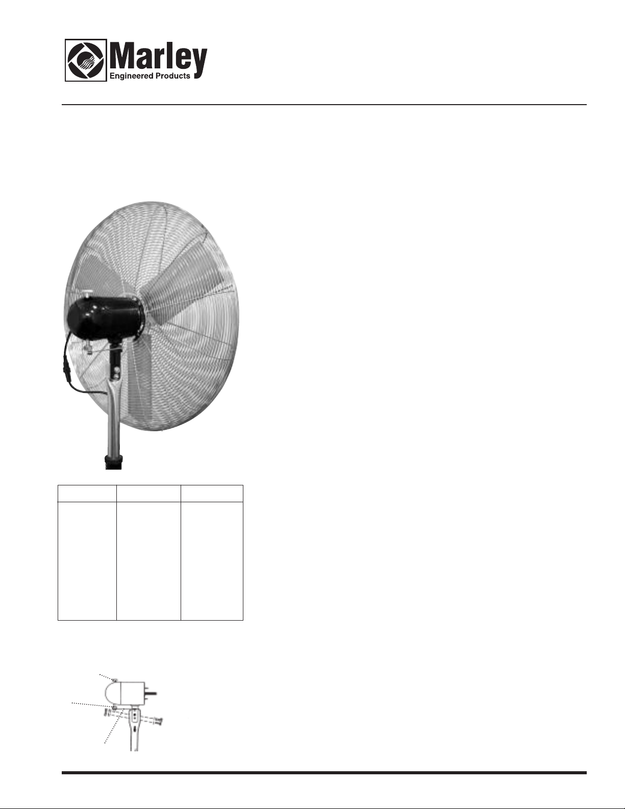
Your oscillating fan head is shipped completely assembled. This head assembly is for pedestal or
wall mount applications only. Choose mount needed and follow installation instructions on back
page.
CAUTION: Do not install oscillating fans upside down as this may allow the fan to fall or become
permanently damaged. Mount only as shown in this manual with the fan head on top of the
Volts
Hz
Amps
Horsepower
Max RPM
Shaft Diameter
Sweep
Tilt
Figure 1
3.
2.
Specifications
24” 30”
120
60
3.1
1/4
1175
1/2”
90˚, or fixed
10˚ up or down
120
60
3.3
1/4
1100
1/2”
90˚, or fixed
10˚ up or down
bracket.
1. Before servicing or cleaning unit, switch power off at service panel and lock service panel to prevent power from being switched on accidentally.
2. Installation work and electrical wiring must be done by qualified person(s) in accordance with all
applicable codes and standards, including fire-rated construction.
3. When cutting or drilling into wall or ceiling, do not damage electrical wiring or other hidden
utilities.
4. Ensure that the power source conforms to the electrical requirements of the motor.
5. To reduce the risk of fire or electric shock, do not use this fan with any solid state motor speed
control.
6. Never allow fan to become wet or damp.
7. Never move or adjust fan height while fan is running.
8. Never put fingers or foreign objects through fan guard.
9. Check all hardware periodically to make sure all is secure.Loose hardware could cause damage to fan.
10.A secondary support cable should be used with any overhead installation.
WARNING: USE OF A THREE-PRONG TO TWO PRONG ADAPTER IS NOT RECOMMENDED.
IMPROPER CONNECTION MAY CREATE THE RISK OF ELECTROCUTION. USE OF SUCH ADAPTER
IS PROHIBITED IN CANADA.
11. Extension cords should not be used with fans. If it is necessary, use only three wire extension
cords with three prong grounded type plugs. Refer to table for correct wire size.
EXTENSION CORD LENGTH WIRE SIZE AWG
UP TO 25 FEET 14
25-50 FEET 12
WARNING: DO NOT DEPEND UPON ANY SWITCH OR THERMOSTAT AS THE SOLE MEANS OF DISCONNECTING POWER WHEN INSTALLING OR SERVICING THE MOTOR. ALWAYS UNPLUG THE
POWER CORD. FAILURE TO DO SO MAY RESULT IN FATAL ELECTRIC SHOCK.
CAUTION: DO NOT MOVE FAN WHILE BLADE IS MOVING. ALWAYS TURN FAN OFF AND LET
BLADE STOP BEFORE ATTEMPTING TO MOVE. DO NOT USE BLADE GUARD TO MOVE FAN.
1. Motor is set for 90˚ sweep when assembled at factory. Make sure both bolts on actuating arm are
tight. See Figure 1. Be sure that lockshaft (3) in Figure 1 is securely tightened full counter clockwise to obtain the “sweep” action. Tighten lockshaft only when blade or motor is at rest. The lockshaft may be hand tightened or a pair of pliers may be used to snug the lockshaft.
2. “Straight blow” (fixed position) is obtained by loosening the lockshaft(3) approximately 1/4 turn
clockwise.
3. The lockshaft will loosen and disengage the oscillating mechanism when the fan assembly is
blocked or prevented from making its full sweep. Remove the blockage and re-tighten the lockshaft to return to its sweeping action.
4. Fan may be tilted 10˚ up or 10˚ down on both pedestal & wall mount application.
5. Do not tighten set screw on support . This is pre-set at factory.
WARNING: MAKE CERTAIN THAT THE FAN IS UNPLUGGED BEFORE ATTEMPTING TO SERVICE,
DISASSEMBLE OR REMOVE ANY COMPONENT!
1. Clean blade and guard with mild soap and water only. DO NOT allow fan motor to get wet.
2. Motor is permanently lubricated - do not oil.
3. Inspect for any damaged or worn parts and replace.
General Safety Information
Operation
Maintenance
1.
NOTE: Fan motor switch and capacitor are field serviceable. Oscillating gear box inside is NOT field
serviceable. Gear box must be removed and sent to the factory for repair or replacement.
Page 2
ADJUSTABLE PEDESTAL COLUMN FOR OSCILLATING FAN
IMPORTANT- REVIEW ALL THE ASSEMBLY INSTRUCTIONS AND
HECK FOR MISSING OR DAMAGED PARTS PRIOR TO STARTING
C
ASSEMBLY
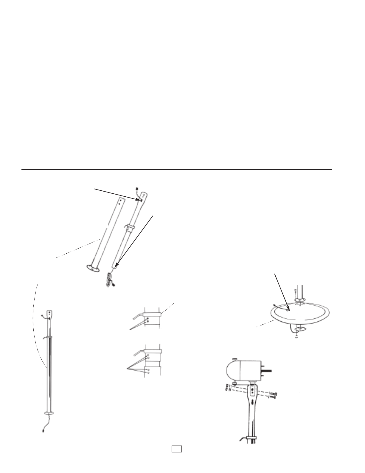
1. Remove 2 sections of adjustable pedestal column from carton. Remove
oval grommet from parts package and install in oval slot near top of
pedestal column. Remove large round grommet from parts package. Turn
grommet “inside out” so that the grove is on the inside and the smooth
side is on the outside. Install grommet over bottom lip of pedestal column. Feed power cord down through top of black section (end with screw
holes). Slide adjustment collar into black section, align screw holes and
secure. Secure adjustment collar to lowest height for assembly. (See
Figure 2)
2. Remove base from carton and insert medium rubber grommet into hole
on surface of fan base.(See Figure 3)
3. Feed power cord from bottom of column down through center hole of fan
base and then back through hole with rubber grommet.(See Figure 3)
4. Align holes in flange at base of column with holes in top of fan base.
Secure using 5/16” x 1” carriage bolts, lockwashers and hex nuts.(See
Figure 3). One of the carriage bolts is to be attached with the 5/16” internal tooth star washer mounted under the bolt head.
OVAL GROMMET
Remove oval grommet from parts
package and install in
oval slot near top pedestal.
This grommet must be installed to
prevent cord damage.
LARGE ROUND
GROMMET
Remove large round grommet from
parts package.
5. Secure fan head assembly to upper column using 1/2” x 1-1/2” hex bolt,
washer, lockwashers and hex nuts,1/4” x 1-1/2” bolt, washer, lockwashers and hex nut. (See Figure 4).
NOTE: Loosen the lockshaft (3) Figure 1, at least 1/4 turn clockwise to dis-
engage the oscillating mechanism of the gear before installing the fan
ead assembly to the pedestal column. This will avoid unnecessary
h
movements of the gear mechanism while the fan head is still being
installed.
6. Loosen adjustment collar and extend fan to proper height.Tighten collar
and connect power cord from column to power cord on motor.
7. Plug power cord from fan into any 120 VAC 3-prong grounded outlet.
Adjustable
Pedestal
Column
Figure 2
Remove 2 phillips head screws.
Align and secure with
2 phillips head screws.
Turn grommet “inside out” so that the
groove is on the inside and the smooth
side is on the outside.
Install grommet over bottom lip of
pedestal column
Adjustment Collar
Pedestal Base
NOTE: When mounting Fan Head
onto pedestal assembly, motor cord
should be on the same side as the
oval grommet on the pedestal. This
will minimize the rubbing of the
flexcord on the pedestal column as
the motor oscillates.
RUBBER
GROMMET
Figure 3
Figure 4
2
Page 3

WALL MOUNT FOR OSCILLATING FAN
CAUTION: Do not install oscillating fans upside down as this may allow the fan
to fall or become permanently damaged. Mount only as shown in this manual
with the fan head on top of the bracket.
1. Securely mount the wall bracket directly to a cinder block wall or vertical I-beam.
Oscillator motors use this
hole only for adjustment.
Figure 5
Drill four 25/64” diameter holes in the proper locations on the mounting surface,
using the wall bracket as a template. 3/8-16 hex bolts are recommended for use
in mounting the bracket to the mounting surface. The bolts should be of sufficient length for the particular surface to which the bracket is to be mounted. Also,
if mounting to a cinder block wall, large surface bearing washers are recommended on the opposite side of the block to ensure the nut has sufficient surface
to be tightened. For installation on wood construction (minimum 2” x 4” stud),
secure bracket with heavy duty lag bolts or screws (not included). For concrete
or masonry installation use heavy duty expansion shields and lag screws (not
included). See Figure 5
NOTE: All installation should be done to meet local building codes.
2. Mount the motor assembly to the wall bracket using 1/2” x 1-1/2” hex bolt and
1/4” x 1-1/2” bolt, washers, lockwashers and hex nuts provided. See Figure 6
3. When mounting oscillating motor and fan assemblies, use only the 1/4” adjustment hole directly below the 1/2” mounting hole on wall mount bracket. See
Figure 5.
NOTE: Use of the wrong hole on the wall bracket will cause the oscillating models
to tilt too much and will cause the oscillating mechanism to bind and cause premature failure.
1/2-13 HHCS
Bolt
1/4-20 HHCS
Bolt
Figure 6
Lockwasher
Lockwasher
1/2-13 Hex Nut
1/4-20 Hex Nut
4. DO NOT use an extension cord. For units which feature two part cordsets, connect the male end of the motor cord to the female end of the cordset. Plug power
cord from fan into any 120 VAC 3 prong, grounded outlet.
SECONDARY SUPPORT CABLE INSTALLATION
For Overhead Wall Mounted Application
Loop secondary support cable around top of fan guard as indicated. Secure cable
making sure both front and back guards are inside loop but cable is not allowed to
touch fan blade (See Figure 5). Secure ends with two cable clamps, loop other end
of cable around any permanent sturdy structural member close to fan (rafter, Ibeam, joist, etc.) and secure ends with two cable clamps. Give enough slack such
that fan will be able to make its full sweep without the support cable restraining its
sweeping action.
IMPORTANT NOTICE: It is important to note the proper installation position of the
cable clamps as illustrated. To obtain maximum holding power, install U-bolt section of clip on dead or short end of cable and saddle on long end of cable (See
Figure 7). Improper installation reduces the efficiency of the connection by as much
as 40 percent.
Figure 7
3
Page 4

REPLACEMENT PARTS FOR LCHHD24-O AND LCHHD30-O
Items that may need replacing
because of loss or damage.
3,5
1
(For Pedestal Mount
Application Only)
2,4
Ref. No. Description Part No.
1 Motor Only-Oscillating 3900-2057-000
2 Guard 24” Front 2504-2040-002
3 Guard 24” Rear 2504-2039-002
4 Guard 30” Front 2504-2038-002
5 Guard 30” Rear 2504-2037-002
6,7
6 Blade 24” 1210-2014-000
7 Blade 30” 1210-2026-000
HOW TO OBTAIN WARRANTY SERVICE AND
WARRANTY PARTS PLUS GENERAL INFORMATION
1. Warranty Service or Parts 1-800-642-4328
2. Purchase Replacement Parts 1-800-654-3545
3. General Product Information www.marleymep.com
Note: When obtaining service always have the following:
1. Model number of the product
2. Date of manufacture
3. Part number or description
Part No. 5200-2392-003
ECR 37011
02/07
4
470 Beauty Spot Rd. East
Bennettsville, SC 29512 USA
 Loading...