

Page 1
J Series (Model B)
Institutional Convector
Dear Owner,
Congratulations! Thank you for purchasing this new heater manufactured by a division of Marley
Engineered Products. You have made a wise investment selecting the highest quality product in the heating industry. Please carefully read and follow the installation and maintenance directions shown in this
manual. You should enjoy years of efficient heating comfort with this product from Marley Engineered
Products... the industry’s leader in design, manufacturing, quality and service.
... The Employees of
Marley Engineered Products
Read Carefully - These instructions are written to help
you prevent difficulties that might arise during installation
of heaters. Studying the instructions first may save you
considerable time and money later. Observe the following
procedures, and cut your mounting time to a minimum.
1. To prevent electrical shock, disconnect all power coming to
heater at main service panel before wiring or servicing.
2. All wiring must be in accordance with the National and Local
Electrical Codes and the heater must be grounded as a precaution against possible electric shock.
3. Verify the power supply voltage coming to heater matches
the ratings printed on the heater nameplate before energizing.
4. Do not insert or allow foreign objects to enter any ventilation
or exhaust opening as this may cause an electric shock,
fire, or damage to the heater.
5. To prevent a possible fire, do not block air intakes or exhaust
in any manner. Keep combustible materials, such as boxes,
crates, drapes, etc., away from heater.
6. A heater has hot and arcing or sparking parts inside. Do not
use it in areas where gasoline, paint or flammable liquids are
used or stored.
7. Use this heater only as described in this manual. Any other
use not recommended by the manufacturer may cause fire,
electric shock, or injury to persons.
8. This heater is not approved for use in hazardous atmospheres
or corrosive atmospheres such as marine, green house
or chemical storage areas.
Installation & Maintenance Instructions
FILE #E21609
1
SA VE THESE INSTRUCTIONS
WARNING
!
Page 2
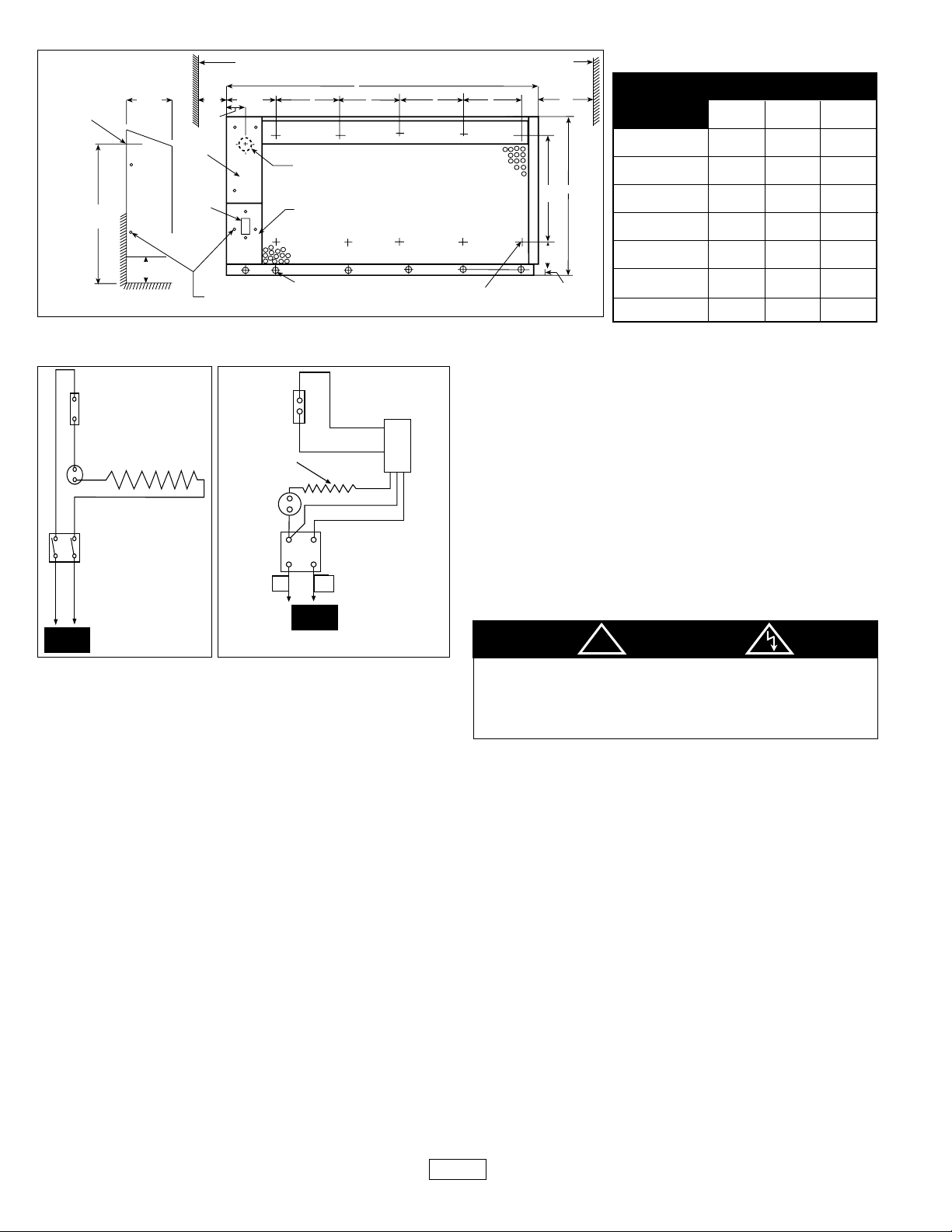
MOUNTING AND WIRING
NOTE: Electrical wiring is to be sized in accordance with National
Electric Code and local codes using at least 75°C type RH, THW
or equivalent insulated wire. See chart located on page 3 for
amp. loads.
1. Locate on vertical wall with length of heater positioned
horizontally.
2. When selecting a mounting location, the following minimum
distances must be observed to insure proper operation.
a. Six (6") inches (152mm) from bottom of heater to floor.
b. One (1.5") inch (38mm) from wall or other obstruction to
the right or left side of heater.
3. Do not mount heater in a recess, since such mounting
interferes with free air circulation, increases temperature and
prevents proper thermostat operation.
NOTE: Unit is shipped with non-tamper resistant screws securing
front cover. Remove screws and discard.
4. Mount the rear panel assembly of the heater to the wall using
the 11/32" (8.7mm) diameter holes (bolts and wall anchors to be
supplied by customer).
5. Install the perforated cover by hooking the top edge of the
cover over the top edge of rear panel.
6. Attach the bottom lip of the perforated cover to the wall using
the 1/4 - 20 x 1" tamper proof screws provided (Wall anchors
to be supplied by customer).
7. Electrical wiring must be brought into heater through 1-3/32"
(27.8mm) diameter hole located in the rear panel.
8. Grounding conductor must be connected to the green pigtail
lead.
9. Make the proper connections following the wiring diagram.
Install disconnect switch cover assembly with (2) #8 x 5/8"
tamper proof screws (provided).
10. Adjust thermostat to the desired setting. Install top access
cover with (4) #8 x 5/8" tamper proof screws (provided).
OPERATION AND MAINTENANCE
To assure efficient operation, follow the simple instructions listed
below.
TO CLEAN HEATER
Because of the convection heating principle which depends upon
a circulation of air through the finned element, dust particles will
periodically be deposited between the fins, and should be
removed occasionally for maximum efficiency of the heater. With
front cover removed, a vacuum cleaner with proper attachments
can easily be worked along the top and bottom of the finned element to clear it of dust deposits.
TO REPAINT, IF DESIRED
The baked enamel finish was chosen to blend with interior decors.
If you wish to repaint the heaters, use high quality household
enamel. No primer is necessary. Do not use rubber base paint.
Paint heater front cover only. Do not paint heating element.
HAZARD OF ELECTRIC SHOCK. DISCONNECT ALL
POWER BEFORE A TTEMPTING TO SERVICE THE
HEA TERS.
WATTAGE
DIMENSIONS
A
24"
608mm
28"
709mm
36"
912mm
48"
1216mm
60"
1520mm
72"
1824mm
96"
2432mm
18"
456mm
18.25"
462mm
B
19.1”
485 mm
11.5"
291mm
15.0"
380mm
14.3"
362mm
13.75"
348mm
16.75"
424mm
C
-
11.5"
291mm
16"
405mm
14.3"
362mm
13.75"
348mm
16.75"
424mm
400
500
750
1000
1250
1500
2000
2
other obstruction
TO POWER
CIRCUIT
!
DANGER
(1000W thru 2000W)
(1250W thru 2000W)
120V thru
277V ONLY
347V and
600V ONLY
(347V) N
(600V)L2
TO POWER
CIRCUIT
Wiring Diagrams
L1
N
A
B
C
(all models)
(1000W, 1 250W, 1 500W)
center line of
1-3/32" dia. hole
in rear panel
for customer entry.
19"
Min.
(481mm)
5"
(127mm)
6" to floor Min.
(152mm)
(25mm)
Top
Access
Cover
Disconnect
Switch
1"
3"
(76mm)
Min.
1 3/4"
(25mm)
Tamper Proof
Screws 10 - 32 x 1/2"
Conduit Entrance
Disconnect Switch Cover
Mounting holes 11/32" (8.7mm) dia. for mtg.
front cover to wall by using 1/4 - 20 x 1"
tamper proof screws supplied.
Thermostat
Element
High
Limit
L1
N
Disconnect
Switch
L1
Thermostat
Limit
Disconnect
Switch
L2 or N
Element
Transformer
Relay
Red
White
Red
Blue
Black
or other obstruction
C
C
(1250W & 1500W o nly)
Mounting holes 11/32" (8.7mm)
dia. for mtg. rear panel to wall
(25mm)
10" 16"
(253mm)
3 7/16"
(87mm)
(6.3mm)
1/4"
Min.
1"
(405mm)
Page 3

IMPORTANT INFORMATION
MODEL NO.
J400B
J408B
J404B
J407B
120
208
240
277
400
400
400
400
3.3
1.9
1.7
1.4
40
40
40
40
J750B
J758B
J754B
J757B
J753B
J1000B
J1008B
J1004B
J1007B
J1003B
J1006B
J1250B
J1258B
J1254B
J1257B
J1253B
J1256B
J1500B
J1508B
J1504B
J1507B
J1503B
J1506B
J2008B
J2004B
J2007B
J2003B
J2006B
208
240
277
347
600
2000
2000
2000
2000
2000
9.6
8.3
7.2
5.8
3.3
130
130
130
130
130
120
208
240
277
347
120
208
240
277
347
120
208
240
277
347
600
120
208
240
277
347
600
120
208
240
277
347
600
500
500
500
500
500
750
750
750
750
750
1000
1000
1000
1000
1000
1000
1250
1250
1250
1250
1250
1250
1500
1500
1500
1500
1500
1500
4.2
2.4
2.1
1.8
1.4
6.3
3.6
3.1
2.7
2.2
8.3
4.8
4.4
3.6
2.9
1.7
10.4
6.0
5.2
4.5
3.6
2.1
12.5
7.2
6.3
5.4
4.3
2.5
45
45
45
45
45
55
55
55
55
55
65
65
65
65
65
65
80
80
80
80
80
80
95
95
95
95
95
95
HEATER
VOLTS
WATTS
AMPS
SHIPS
WT.(lbs.)
3
MODEL NO. J757B DATECODE 0295
ROOM HEATER
APPAREIL DE CHAUFFAGE
277 750 2.7
VOLTS WATTS AMPS.
774G LISTED
ROOM HEATER
MARLEY ENGINEERED PRODUCTS
BENNETTSVILLE, SC 29512 4104-2150-010
NAMEPLATE
J500B
J508B
J504B
J507B
J503B
Page 4

HOW TO ORDER REPAIR PARTS
In order to obtain any needed repair or replacement
parts, warranty service or technical information, please
contact Marley Engineered Products toll-free by calling 1800-642-HEAT.
When ordering repair parts, always give the information
listed as follows:
1. The Part Number
2. The Model Number
3. The Part Description
4. Date of Manufacture
LIMITED W ARRANTY
All products manufactured by Marley Engineered Products are warranted against defects in workmanship and materials for one year
from date of installation, except heating elements which are warranted against defects in workmanship and materials for five years
from date of installation. This warranty does not apply to damage from accident, misuse, or alteration; nor where the connected voltage is more than 5% above the nameplate voltage; nor to equipment improperly installed or wired or maintained in violation of the
product’s installation instructions. All claims for warranty work must be accompanied by proof of the date of installation.
The customer shall be responsible for all costs incurred in the removal or reinstallation of products, including labor costs, and shipping costs incurred to return products to Marley Engineered Products Service Center.Within the limitations of this warranty, inoperative units should be returned to the nearest Marley authorized service center or the Marley Engineered Products Service Center,
and we will repair or replace, at our option, at no charge to you with return freight paid by Marley. It is agreed that such repair or
replacement is the exclusive remedy available from Marley Engineered Products.
THE ABOVE WARRANTIES ARE IN LIEU OF ALL OTHER WARRANTIES EXPRESSED OR IMPLIED. AND ALL IMPLIED WARRANTIES OF MERCHANTABILITY AND FITNESS FOR A PARTICULAR PURPOSE WHICH EXCEED THE AFORESAID
EXPRESSED WARRANTIES ARE HEREBY DISCLAIMED AND EXCLUDED FROM THIS AGREEMENT. MARLEY ENGINEERED
PRODUCTS SHALL NOT BE LIABLE FOR CONSEQUENTIAL DAMAGES ARISING WITH RESPECT TO THE PRODUCT,
WHETHER BASED UPON NEGLIGENCE, TORT, STRICT LIABILITY, OR CONTRACT.
Some states do not allow the exclusion or limitation of incidental or consequential damages, so the above exclusion or limitation may
not apply to you. This warranty gives you specific legal rights, and you may also have other rights which vary from state to state.
For the address of your nearest authorized service center, contact Marley Engineered Products in Bennettsville, SC, at 1-800-642-
4328. Merchandise returned to the factory must be accompanied by a return authorization and service identification tag, both available from Marley Engineered Products. When requesting return authorization, include all catalog numbers shown on the products.
Part No. 5200-2251-003
4
ECR 33823
05/98
470 Beauty Spot Rd. East
Bennettsville, SC 29512 USA
 Loading...