

Page 1
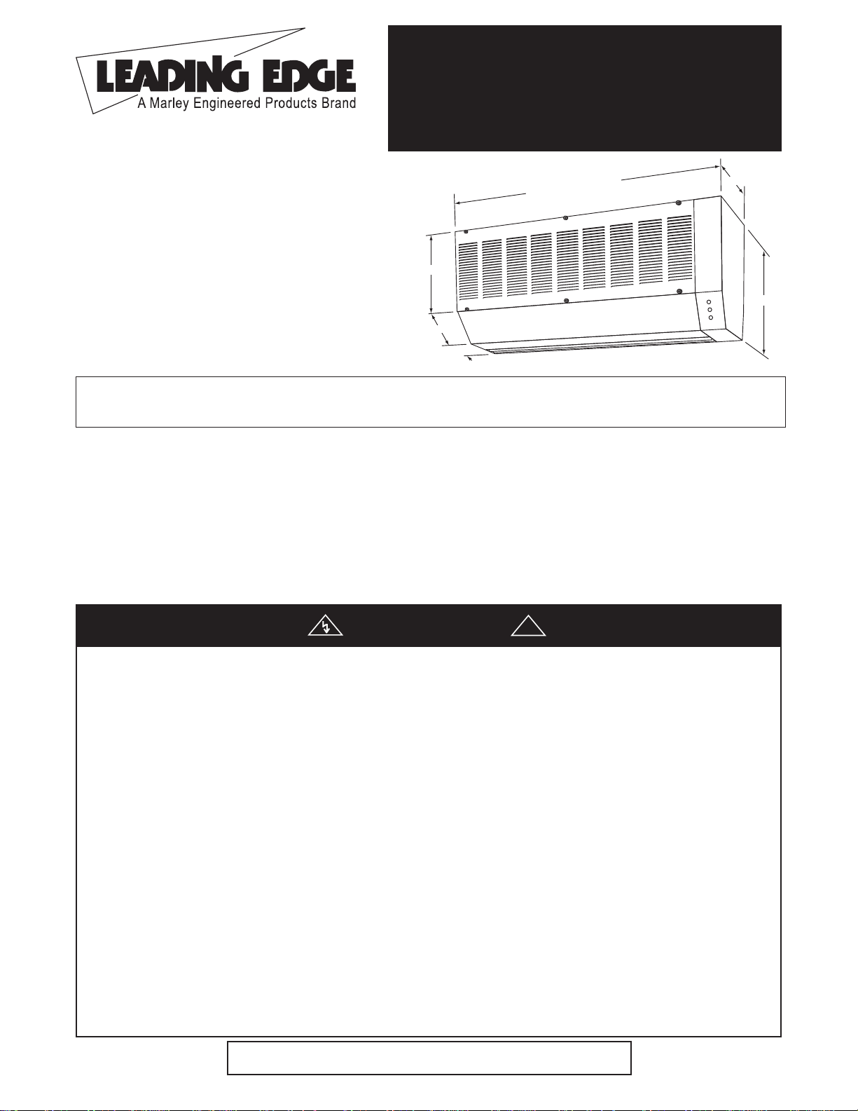
HIGH VELOCITY SERIES
ELECTRICALLY HEATED AIR CURTAINS
8 KW THROUGH 48 KW
42” THROUGH 144”
SAVE THESE INSTRUCTIONS
Dear Owner,
Congratulations! Thank you for purchasing this new air curtain manufactured by Marley Engineered Products. You have
made a wise investment selecting the highest quality product in the industry. Please carefully read the installation and
maintenance instructions shown in this manual. You should enjoy years of efficient service with this product from Marley
Engineered Products... the industry’s leader in design, manufacturing, quality and service.
... The Employees of Marley Engineered Products
Installation & Maintenance Instructions
®
Read Carefully - These instructions are written to help you
prevent difficulties that might arise during installation of the
unit. Studying the instructions first may save you considerable time and money later. Observe the following procedures, and cut your installation time to a minimum.
CAUTION - TO REDUCE RISK OF FIRE AND ELECTRIC
SHOCK OBSERVE THE FOLLOWING:
1. Read all instructions before using this unit.
2. Disconnect all power coming to the unit at main service panel
before wiring or servicing. Lock service panel to prevent power
from being switched on accidentally.
NOTE: Do not depend upon a thermostat or other switch as the sole
means of disconnecting power when installing or servicing the unit.
Always disconnect power at the main service panel as described
above.
3. All wiring should be done by a qualified electrician, using copper
wire only and in accordance with the National Electrical Code
(NEC), all applicable code and ordinances, including fire rated
construction, and all sections of this manual. Any variance voids
the warranty and may create unsafe conditions.
4. To prevent the risk of electric shock, the unit must be properly
grounded. This should be accomplished by connecting a bonding conductor between the disconnecting means and the
grounding lug provided in the Main Control Box of the unit. Each
cabinet wiring compartment is provided with grounding lugs for
connecting bonding conductors between each cabinet and the
Main Control Box. To ensure a proper ground, the grounding
means must be tested by a qualified electrician.
5. Verify the power supply voltage coming to unit matches the ratings printed on the heater nameplate before energizing.
6. This unit can be hot when in use. To avoid burns, do not let bare
skin touch hot surfaces.
7. Do not insert or allow foreign objects to enter any ventilation or
exhaust opening as this may cause an electric shock, fire or
damage to the unit.
8. Do not block air intakes or exhaust in any manner. Keep combustible materials, such as crates, drapes, etc., away from air
curtain.
9. This unit has hot and arcing or sparking parts inside. Do not use
it in areas where gasoline, paint or flammable liquids are used
or stored.
10. Use this unit only as described in this manual. Any other use
not recommended by the manufacturer may cause fire, electric
shock, or injury to persons. If you have questions contact the
manufacturer.
11. This unit is not approved for use in corrosive atmospheres such
as marine, green house or chemical storage areas.
12. Do not use outdoors
WARNING
!
IMPORTANT INSTRUCTIONS
13”
15 3/4”
11 7/8”
4 7/8”
8 1/4”
Refer to individual model numbers
for unit width
Page 2

High Velocity Series Specifications and Performance
NUMBER AIR DELIVERY @ NOZZLE OUTLET APPROX.
MODEL NOZZLE Volts Heater # MOTORS @ OF CONTROL MAX VEL AVG VEL AIRFLOW SHIPPING
NUMBER WIDTH (IN) AC Watts BTU/HR HP CABINETS VOLTAGE (FPM) (FPM) (CFM) WEIGHT (LBS)
1/2 HP Models
E42081#00HE 42 # 8000 27,320 1 @ 1 1 24 5250 3990 3770 109
E48081#00HE 48 # 8000 27,320 1 @ 1 1 24 5250 3890 4200 116
E60081#00HE 60 # 8000 27,320 1 @ 1 1 24 5250 3675 4960 132
E72162#00HE 72 # 16000 54,640 2 @ 1 2 24 5250 4200 6800 197
E84162#00HE 84 # 16000 54,640 2 @ 1 2 24 5250 3990 7540 210
E96162#00HE 96 # 16000 54,640 2 @ 1 2 24 5250 3890 8400 268
E108243#00HE 108 # 24000 81,960 3 @ 1 3 24 5250 4200 10200 291
E120243#00HE 120 # 24000 81,960 3 @ 1 3 24 5250 4075 10940 304
E132243#00HE 132 # 24000 81,960 3 @ 1 3 24 5250 3975 11800 317
E144243#00HE 144 # 24000 81,960 3 @ 1 3 24 5250 3890 12600 330
E42121#00HE 42 # 12000 40,980 1 @ 1 1 24 5250 3990 3770 109
E48121#00HE 48 # 12000 40,980 1 @ 1 1 24 5250 3890 4200 116
E60121#00HE 60 # 12000 40,980 1 @ 1 1 24 5250 3675 4960 132
E72242#00HE 72 # 24000 40,980 2 @ 1 2 24 5250 4200 6800 197
E84242#00HE 84 # 24000 81,960 2 @ 1 2 24 5250 3990 7540 210
E96242#00HE 96 # 24000 81,960 2 @ 1 2 24 5250 3890 8400 268
E108363#00HE 108 # 36000 81,960 3 @ 1 3 24 5250 4200 10200 291
E120363#00HE 120 # 36000 122,940 3 @ 1 3 24 5250 4075 10940 304
E132363#00HE 132 # 36000 122,940 3 @ 1 3 24 5250 3975 11800 317
E144363#00HE 144 # 36000 122,940 3 @ 1 3 24 5250 3890 12600 330
E42161#00HE 42 # 16000 122,940 1 @ 1 1 24 5250 3990 3770 109
E48161#00HE 48 # 16000 54,640 1 @ 1 1 24 5250 3890 4200 116
E60161#00HE 60 # 16000 54,640 1 @ 1 1 24 5250 3675 4960 132
E72322#00HE 72 # 32000 54,640 2 @ 1 2 24 5250 4200 6800 197
E84322#00HE 84 # 32000 54,640 2 @ 1 2 24 5250 3990 7540 210
E96322#00HE 96 # 32000 109,280 2 @ 1 2 24 5250 3890 8400 268
E108483#00HE 108 # 48000 109,280 3 @ 1 3 24 5250 4200 10200 291
E120483#00HE 120 # 48000 109,280 3 @ 1 3 24 5250 4075 10940 304
E132483#00HE 132 # 48000 163,920 3 @ 1 3 24 5250 3975 11800 317
E144483#00HE 144 # 48000 163,920 3 @ 1 3 24 5250 3890 12600 330
# - INDICATE VOLTAGE: 3 = 208V 3-PH, 4 = 240V/208V 3-PH, 5 = 480V 3-PH.
Note: Multiply listed wattage by .75 for actual 208V rating. Maximum
15 kilowatts per cabinet at 240V.
3/4 HP Models
E42081#30HE 42 # 8000 27,320 1 @ 3 1 24 7200 4760 4495 117
E48081#30HE 48 # 8000 27,320 1 @ 3 1 24 7200 4615 4980 125
E60081#30HE 60 # 8000 27,320 1 @ 3 1 24 7200 4320 5830 141
E72162#30HE 72 # 16000 54,640 2 @ 3 2 24 7200 5040 8160 211
E84162#30HE 84 # 16000 54,640 2 @ 3 2 24 7200 4760 8990 226
E96162#30HE 96 # 16000 54,640 2 @ 3 2 24 7200 4615 9960 241
E108243#30HE 108 # 24000 81,960 3 @ 3 3 24 7200 5040 12240 312
E120243#30HE 120 # 24000 81,960 3 @ 3 3 24 7200 4870 13070 327
E132243#30HE 132 # 24000 81,960 3 @ 3 3 24 7200 4730 14040 342
E144243#30HE 144 # 24000 81,960 3 @ 3 3 24 7200 4615 14940 357
E42121#30HE 42 # 12000 40,980 1 @ 3 1 24 7200 4760 4495 117
E48121#30HE 48 # 12000 40,980 1 @ 3 1 24 7200 4615 4980 125
E60121#30HE 60 # 12000 40,980 1 @ 3 1 24 7200 4320 5830 141
E72242#30HE 72 # 24000 40,980 2 @ 3 2 24 7200 5040 8160 211
E84242#30HE 84 # 24000 81,960 2 @ 3 2 24 7200 4760 8990 226
E96242#30HE 96 # 24000 81,960 2 @ 3 2 24 7200 4615 9960 241
E108363#30HE 108 # 36000 81,960 3 @ 3 3 24 7200 5040 12240 312
E120363#30HE 120 # 36000 122,940 3 @ 3 3 24 7200 4870 13070 327
E132363#30HE 132 # 36000 122,940 3 @ 3 3 24 7200 4730 14040 342
E144363#30HE 144 # 36000 122,940 3 @ 3 3 24 7200 4615 14940 357
E42161#30HE 42 # 16000 122,940 1 @ 3 1 24 7200 4760 4495 117
E48161#30HE 48 # 16000 54,640 1 @ 3 1 24 7200 4615 4980 125
E60161#30HE 60 # 16000 54,640 1 @ 3 1 24 7200 4320 5830 141
E72322#30HE 72 # 32000 54,640 2 @ 3 2 24 7200 5040 8160 211
E84322#30HE 84 # 32000 54,640 2 @ 3 2 24 7200 4760 8990 226
E96322#30HE 96 # 32000 109,280 2 @ 3 2 24 7200 4615 9960 241
E108483#30HE 108 # 48000 109,280 3 @ 3 3 24 7200 5040 12240 312
E120483#30HE 120 # 48000 109,280 3 @ 3 3 24 7200 4870 13070 327
E132483#30HE 132 # 48000 163,920 3 @ 3 3 24 7200 4730 14040 342
E144483#30HE 144 # 48000 163,920 3 @ 3 3 24 7200 4615 14940 357
# - INDICATE VOLTAGE: 3 = 208V 3-PH, 4 = 240V/208V 3-PH, 5 = 480V 3-PH.
Note: Multiply listed wattage by .75 for actual 208V rating. Maximum
15 kilowatts per cabinet at 240V.
Page 3
GENERAL INFORMATION
Air curtains produce a wall of continuously flowing air that acts as
a thermal barrier against outside air and provides protection
against insects, dust, odor, fumes and other contaminant’s.
Maintains interior conditioned temperature by preventing heated or
cooled air from escaping through open doorways. Heated air curtains are engineered to treat incoming cold air at customers’
entrance areas. Used over front door entrances, heated air curtains supplement existing heat to prevent infiltration of colder outside air. Heated units are not recommended for areas subject to
high winds.
The heated air curtains covered by this Installation & Maintenance
Instructions are permanently installed units intended for permanent
connection to single electrical supply source and are intended to
be located over doorways at least 7 ft. above the floor. The units
may be installed with zero minimum clearances from combustibles
on three sides of the unit and the minimum clearance from the
adjacent wall to the hinged door of the main control box is 36
inches.
Each cabinet employs a dual shaft motor, driving two blower type
air circulators causing air flow over a heater assembly. The heater
assembly consists of two sections, one section per blower. The
heater assembly is controlled by contactors with 24 volt AC low
voltage coils. A replaceable thermal cut-off or one shot protective
device is provided on each leg of each assembly. Each section is
provided with an automatic reset overheat protective device. In
case of overheating, the automatic resets will shut off only the heat
contactor for the heater assembly in the cabinet associated with it
and not the fan contactor and thus airflow should keep on going.
Each cabinet in a multiple cabinet installation are independent of
each other as far as the operation of the auto resets are concerned. Each cabinet will have its own control compartment with a
heating contactor with an indicator light and a fan contactor and the
required control terminals for interconnection.
When facing the inlet grille of the unit, the main control box is
attached on the right side of the combination. A maximum of three
supplementary 60 amp rated circuit breakers (or 60A load fuses)
will be provided for units with full load rating greater than 48 amps.
Field control terminal blocks are also provided with the Main
Control box. A class 2 certified, 24V secondary, 75 VA control
transformer is provided. Class 2 wiring may be used for controls
but it is recommended to use Class 1 wiring for controls since
these are usually located in a commercial-industrial environment.
The load on the thermostat will always be one small relay (4VA) for
heat and another relay for the fan circuit whether the unit is a single, a double or a triple cabinet installation. Any standard low voltage (24V) heating thermostat may be used.
On the Main Control Panel are three indicator lights. These lights
serve the following functions:
Top Light - Power is on to the unit.
Middle Light - The heating elements are on in the unit.
Bottom Light - The fan is on in the unit.
If the “HEAT ON” light is lit at the Main Control Box, the indicator
light at each cabinet control compartment should also be lit. The
cabinet with an unlit light in this instance will need investigation.
Either the bulb is defective or the automatic reset protective
devices in this cabinet has functioned and taken the heating contactor out of circuit. The airflow should also be checked on this
cabinet. The air passageways may be blocked or the blower
wheels loose or turning in the wrong direction.
These air curtains are provided with a pressure differential switch
with the sensing tube located on the low pressure or suction side of
the switch and the other end on the inlet side of the blower. It has
been so located that when the motors are rotating in the wrong
direction there will not be enough suction to close the normally open
contact of the pressure switch and thus prevent the heating contactor and the associated pilot light from coming on. When this happens check for correct rotation of the motor and for anything else
that may cause the blower from delivering the required air flow.
UNPACKING
For Single Cabinet Units: 42”, 48” and 60”
1. With packaged unit on the floor, carton arrows should point
upward.
2. Carefully remove staples from top of carton and fold back sides.
3. Carefully remove cabinet from carton by lifting out unit using finger holes in styrofoam side inset and place on work surface.
CAUTION: Do not attempt to lift this air curtain by its louver or
damage may result.
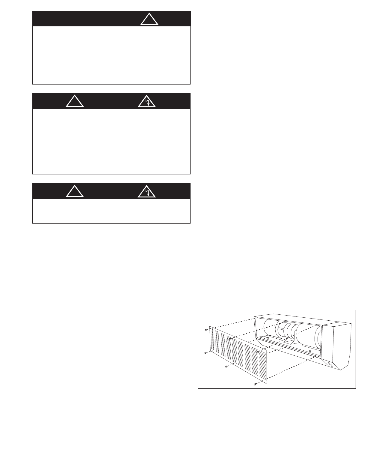
4. Unscrew six (6) knurled nuts and remove air intake grille. (See
Figure 3)
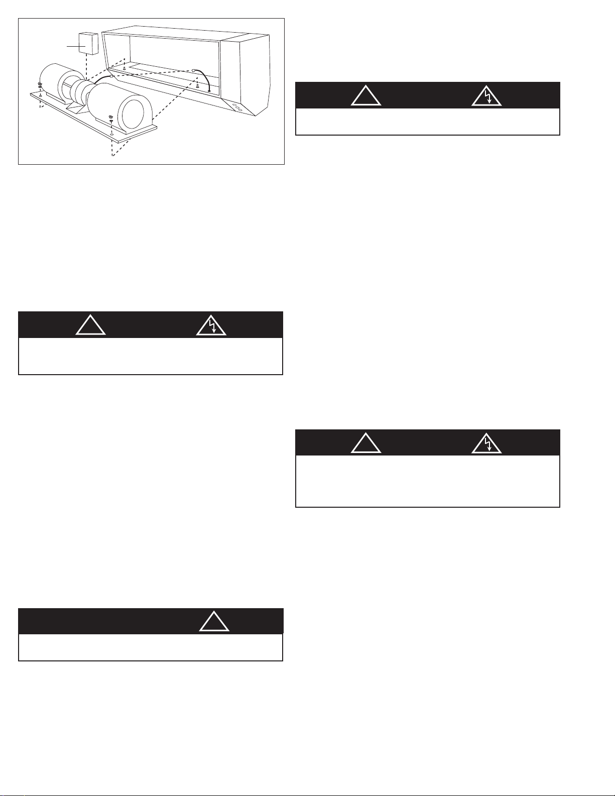
5. Carefully disconnect motor electric cord from socket and plug
assembly and remove two wing nuts on blower base. (See
Figure 4)
NOTE: Unit is shipped with styrofoam motor support block which
must be discarded at this time.
6. Carefully remove pressure switch hose from clamp on the right
blower.
!
WARNING
ALWAYS DISCONNECT POWER AT THE MAIN DISCONNECT
OR CIRCUIT BREAKER BEFORE INSTALLING OR SERVICING THIS HEATED AIR CURTAIN. IF THE POWER DISCONNECT IS OUT OF SIGHT OR IS LOCATED GREATER THAN
50 FEET FROM THE MAIN PANEL OF THIS HEATED AIR
CURTAIN, LOCK THE MAIN DISCONNECT IN THE OPEN
POSITION AND TAG IT TO PREVENT UNEXPECTED APPLICATION OF POWER. FAILURE TO DO SO COULD RESULT
IN FATAL ELECTRICAL SHOCK.
THIS HEATED AIR CURTAIN AND ITS SUB-ASSEMBLIES AND
CONTROLS SHOULD BE INSTALLED BY QUALIFIED PERSONNEL, USING COPPER WIRES AND IN ACCORDANCE
WITH THE NATIONAL ELECTRICAL CODE (NEC) AND ALL
APPLICABLE LOCAL CODES AND ORDINANCES.
NOTE: A MAIN DISCONNECT OR CIRCUIT BREAKER IS
REQUIRED AHEAD OF THE MAIN PANEL OF THIS HEATED
AIR CURTAIN.
!
WARNING
TO REDUCE THE RISK OF FIRE OR ELECTRIC SHOCK, DO
NOT USE THIS AIR CURTAIN WITH ANY SOLID STATE
SPEED CONTROL DEVICE.
CAUTION
!
Figure 3
Page 4
7. To remove motor blower assembly, lift from rear of motor housing to prevent damage and misalignment to shaft and blower
wheels. Once the motor/blower assembly is removed, the
heater assembly will be accessed.
NOTE: After unpacking unit, inspect carefully for any damage that
may have occurred during transit. Check for loose, missing or damaged parts. The hinged Cabinet Wiring Compartment cover should
also be opened to inspect the components and wiring inside.
8. Make sure the open coil elements do not touch any metal part
and all the porcelains holding the elements are not broken and
are in their proper place.
For 2 Cabinet Units: 72”, 84” and 96” See Figure 5
1. With packaged units on the floor, carton arrows should point
upward. Cartons are marked A & B.
2.
Follow Steps 2 through 8 for Single Cabinet Units.
NOTE: Cabinet A (left), Cabinet B (right). Carton labeled
Cabinet B will contain the Main Control Box and all harness
wires and parts bag to interconnect the two cabinets.
For 3 Cabinet Units: 108”, 120”, 132” and 144” See Figure 6
1. With packaged units on the floor, carton arrows should point
upward. Cartons are marked A, B and C.
2.
Follow Steps 2 through 8 for Single Cabinet Units.
NOTE: Cabinet A (left), Cabinet B (center), Cabinet C (right).
Carton labeled Cabinet C will contain the Main Control Box
and harness wires and parts bag to interconnect the three
cabinets. Cabinet B may also have harness wires to interconnect to Cabinet A.
INSTALLATION
For Single Cabinet Units:
NOTE: All installation should be done to meet local building codes.
1. Using template provided, determine mounting location.
2. Drill holes and attach mounting hardware (not included).
3. Mount cabinet on wall and securely tighten hardware.
4. Replace motor/blower assembly in cabinet. Pass pres-
sure switch hose through proper hole on blower base.
Reconnect motor electric cord plug assembly.
5. Attach pressure switch hose to right blower housing.
6. Secure two wing nuts on blower base.
7. Replace intake grille with louvers facing down and fasten
knurled nuts.
Field Power Wiring: Refer to Wiring Diagram and
Nameplate.
1. Before wiring be sure that available power supply, voltage,
phase and frequency corresponds to that specified on unit rating plate. In addition, make certain that service capacity is sufficient to handle load imposed by the heated air curtain.
2. Install all wiring, protection and grounding in accordance with
the National Electrical Code (NEC) and all local requirements.
3. Run proper size copper power supply conductors from the field
power supply disconnecting means (supplied by others) with
insulation rated 75 degrees C minimum (167º F) to the power
supply blocks provided at the Main Control Box of the air curtain. This field supplied disconnecting means shall be provided
to disconnect the heater, motor controller(s) and any supplementary overcurrent protective devices from all ungrounded
conductors. This disconnecting means shall be within sight of
the heater, motor controller(s) or supplementary protective
devices. If it is not within sight or is located greater than 50
feet, disconnecting means shall be capable of being locked in
the open position.
4. The heater control box must have an unbroken electrical
ground from its Main Control Box to its field supplied disconnecting means to minimize personal injury in case an electrical
fault should occur.
5. Always refer to nameplate data and wiring diagram located on
the inside of the hinged cover of the main control box for
important information and other data before proceeding with
wiring of the unit.
NOTE: This heated air curtain is equipped with a step-down
transformer 24V control circuit. Any standard 24V heating thermostat with or without fan control may be used. Door switches
may be used to control the operation of the unit. A door switch
may be connected to control the operation of the fan only or it
can be connected in parallel with the heating thermostat to call
for fan and heat every time the door is opened. The thermostat
may call for fan and heat even when door is closed. The step
down transformer is a 75 VA approved Class 2 transformer and a
control knockout is provided with the control terminal blocks
spaced away from power wire to allow Class 2 wiring for controls
but it is recommended to use Class 1 wiring, especially to door
switches to protect it from physical damage in an industrial or
commercial environment.
6. Replace hinged cover of the main control box.
7. Unit is ready for operation.
8. Restore power to the unit. Call for heat through the thermostat
or through the door switch if supplied. Unit should run. Check
for correct air flow.
9. Inspect unit for excessive vibration during operation. If exces-
sive vibration is noticeable, disconnect power supply. Inspect
mounting installation and refer to “Trouble Shooting Chart” for
probable cause.
Field Control Wiring: Refer to Wiring Diagram.
!
WARNING
Make sure no combustible material nor any other foreign material falls on this heating element cavity while it is exposed with
the motor/ blower assembly out of the cabinet
Figure 4
CAUTION
!
THE HARDWARE AND THE SUPPORTING STRUCTURE MUST
BE CAPABLE OF SUPPORTING A MINIMUM 150 LB LOAD.
!
WARNING
ALL HEATED AIR CURTAINS SHOULD BE INSTALLED BY
QUALIFIED PERSONNEL.
!
WARNING
THE MOTORS OF THIS HEATED AIR CURTAIN HAVE AN
INTERNAL SELF RESETTING THERMAL OVERLOAD PROTECTOR. ALWAYS DISCONNECT FROM POWER SUPPLY
BEFORE SERVICING.
Styrofoam
support
block
Page 5

FOR INSTALLATION OF MULTIPLE CABINET AIR
CURTAINS
For 2 Cabinet Units: 72”, 84” and 96” See Figure 5
NOTE: All installation should be done to meet local building codes.
1. Using template provided, determine mounting location
for Cabinet A (left side), left of centerline.
2. Drill holes and attach mounting hardware (not included)
for Cabinet A.
3. Mount Cabinet A on wall and securely tighten hardware.
4. Repeat steps 1,2 and 3 for mounting Cabinet B (right
side), right of centerline.
5. Secure Cabinet A to Cabinet B using parts provided in
installation kit. After alignment of cabinets is completed, carefully secure all assembly mounting hardware.
6. Install motor/blower assembly in Cabinet A. Pass pressure switch hose through proper hole on blower base.
Attach hose to right blower. Secure two wing nuts on
blower base. Reconnect motor (A) electric cord plug
assembly.
7. Install motor/blower assembly (B) in Cabinet B.
Pass
pressure switch hose through proper hole on blower base.
Attach hose to right blower. Secure two wing nuts on blower
base. Reconnect motor (B) electric cord plug assembly.
8. Replace intake grilles with louvers facing down and refasten
knurled nuts.
9. Refer to “Field Power Wiring” and “Field Control Wiring” sections for single cabinet installation in this manual. All
instructions and safety warnings and notes also apply to
electrical connections of multiple cabinets. Additional steps
are necessary only for harness connections of Cabinet A to
Cabinet B and/or to the Main Control Box.
10. Refer to wiring diagram on the inside of the hinged cover of
the Main Control Box and to applicable wiring diagrams in this
manual. Harness wires are provided with the right ends of
the harness wires already connected to the unit and the
installer has to connect the left ends of the harness wires to
the correct terminal points as shown in the diagram. The
Cabinet wiring compartment covers will have to be opened.
These covers are also hinged to the cabinets. Route and
locate wiring and wire strap the wires as shown in Figure 9
and allow for the movement of the wires as the covers are
opened and closed.
11. Replace all hinged covers.
12. Unit is ready for operation.
13. Restore power to the unit. Call for heat through the thermostat or through the door switch if supplied. Unit should run.
Check for correct air flow.
14. Inspect unit for excessive vibration during operation. If
excessive vibration is noticeable, disconnect power supply.
Inspect mounting installation and refer to “Trouble Shooting
Chart” for probable cause.
For 3 Cabinet Units: 108”, 120”, 132” and 144” See Figure 6
NOTE: All installation should be done to meet local building codes.
1. Determine mounting location of center cabinet (See Figure 6).
2. Using template provided, determine mounting location for
Cabinet A (left side), left of center cabinet.
3. Drill holes and attach mounting hardware (not included) for
Cabinet A.
4. Mount Cabinet A on wall and securely tighten hardware.
5. Repeat steps 1, 2, 3 and 4 for mounting Cabinet B (center).
6. Repeat steps 1, 2, 3 and 4 for mounting Cabinet C (right),
right of center cabinet.
7. Secure Cabinet A to Cabinet B to Cabinet C using parts provided in installation kit. After alignment of cabinets is completed, carefully secure all assembly mounting hardware.
8. Install motor/blower assembly (A) in Cabinet A. Pass pressure switch hose through proper hole on blower base.
Attach hose to right blower. Secure two wing nuts on blower
base. Reconnect motor (A) electric cord plug assembly.
9. Install motor/blower assembly (B) in Cabinet B. Pass pressure switch hose through proper hole on blower base.
Attach hose to right blower. Secure two wing nuts on blower
base. Reconnect motor (B) electric cord plug assembly.
10. Install motor/blower assembly (C) in Cabinet C. Pass pressure switch hose through proper hole on blower base.
Attach hose to right blower. Secure two wing nuts on blower
base. Reconnect motor (C) electric cord plug assembly.
11. Replace intake grilles with louvers facing down and fasten
knurled nuts.
12. Refer to “Field Power Wiring” and “Field Control Wiring” sections for single cabinet installation in this manual. All instruction and safety warning and notes also apply to electrical
connections of multiple cabinets. Additional steps are necessary only for harness connection of Cabinet A to Cabinet B
and Cabinet B to Cabinet C and/or to the Main control Box.
13. Refer to wiring diagram on the inside of the hinged cover of
the Main control Box and to applicable wiring diagrams in
this manual. Harness wires are provided with the right ends
of the harness wires already connected to the unit and the
installer has to connect the left ends of the harness wire to
the correct terminal points as shown in the diagram. The
cabinet wiring compartment covers will have to be opened.
These covers are also hinged to the cabinets. route and
locate wiring and wire strap the wires as shown in Figure 9
and allow for the movement of the wires as the hinged covers are opened and closed.
14. Replace all hinged covers.
15. Unit is ready for operation.
16. Restore power to the unit. Call for heat through the thermostat or through the door switch if supplied. Unit should run.
Check for correct air flow.
17. Inspect unit for excessive vibration during operation. If
excessive vibration is noticeable, disconnect power supply.
Inspect mounting installation and refer to “Trouble Shooting
Chart” for probable cause.
CAUTION
!
THE HARDWARE AND THE SUPPORTING STRUCTURE MUST
BE CAPABLE OF SUPPORTING A MINIMUM 300 LB LOAD.
CAUTION
!
THE HARDWARE AND THE SUPPORTING STRUCTURE MUST
BE CAPABLE OF SUPPORTING A MINIMUM 500 LB LOAD.
Cabinet A
Cabinet B
Figure 5
Figure 6
Cabinet A
Cabinet B
Cabinet C
Page 6

OPERATION
1. After power has been connected to unit, unit is ready to
respond to its control devices such as the thermostat or door
switches.
2. Air direction at outlet can be controlled by adjustable vanes
at the nozzle which compensates for possible draft conditions.
NOTE: Air direction settings shown in Figures 7 & 8.
NOTE: Cold air will try to escape near top of doorway. Air flow
can be controlled by direction of nozzle louvers.
NOTE: Each unit is supplied with an air flow probing switch which
is located in each cabinet compartment and this is supplied with a
hose located in the suction side of the blower. A blower turning in
the wrong direction may be prevented from turning the heat on by
this switch.
MAINTENANCE
NOTE: Ball bearings are permanently lubricated and require no
further lubrication.
Cleaning:
1. The air curtain cabinet(s) may be wiped off with a damp
cloth. Do not allow motor to get wet. Do not use solvents or
harsh detergents.
NOTE: Keep air intake louvers clear of dirt and dust accumulation which could affect performance.
2. Check blower wheels for accumulated dirt twice a year and
clean. If disassembly is required, see “General Servicing”
section.
GENERAL SERVICING
1. To remove motor/blower assembly, repeat steps 4, 5, 6 and 7
in “Unpacking” section.
2. Place motor/blower assembly on workbench.
3. To replace blower wheel, remove the three slotted hex head
screws on outer blower ring assembly (See Figure 10,
Replacement Parts Illustration). The wheel is held onto shaft
by two hex head screws.
4. To remove motor:
a. Remove blower wheels. (See Step 3 above).
b. Remove blower scroll (six hex head screws).
c. Unscrew and remove motor mounts.
5. To remove heater assembly:
a. Remove blower wheels. (See Step 3 above).
b. Remove heater assembly (two screws). Disconnect two
yellow wires and blue, black and red wires from heating contactor. Pass wires through bushing as you pull out the
heater assembly.
6. To replace heater assembly: Do the reverse of Step 5 above.
NOTE: To re-assemble, repeat steps 4, 5 and 6 in installation
section for single cabinet units.
7. Replace motor/blower assembly.
!
WARNING
ALL ELECTRICAL POWER MUST BE DISCONNECTED
WHEN INSTALLING OR SERVICING THIS EQUIPMENT.
MORE THAN ONE DISCONNECT SWITCH MAY BE
REQUIRED TO REMOVE POWER FROM THE UNIT.
Figure 7 - Desired Air Flow Adjustment for Temperature
and Humidity Control.
Figure 8 - Desired Air Flow Adjustment for Insect
and Dust Control.
!
WARNING
IF SERVICE IS REQUIRED, IT SHOULD BE DONE BY QUALIFIED PERSONS ONLY.
ALWAYS DISCONNECT POWER SUPPLY BEFORE SERVICING
IMPORTANT
!
NOTE POSITION OF WHEELS TO PREVENT RUBBING WHEN
REPLACED.
Figure 9 - Main control box cover & cabinet compartment
cover shown open and with air intake grille removed.
Page 7

TROUBLE SHOOTING CHART
Symptom Possible Cause Corrective Action
Fan inoperative 1. Blown fuse or open circuit breaker. 1. Replace fuse or reset circuit breaker
2. Electricity turned off. 2. Contact local power company.
3. Loose motor cord connection. 3. Re-check all connections.
4. Thermostat off/defective 4. Call for fan/Replace.
5. Defective fan relay/contactor. 5. Replace.
6. Defective fan relay/contactor. 6. Replace.
7. Defective capacitor (1 phase unit only) 7. Replace.
8. Defective motor. 8. Replace.
9. Wrong wiring. 9. Correct wiring.
Excessive noise 1. Wheel rubbing on housing. 1. Center wheel.
2. Motor base/blower loose. 2. Tighten mounting bolts.
3. Defective motor bearings. 3. Replace motor.
Insufficient air flow 1. Improper voltage. 1. Reconnect proper voltage/or change unit
exchange unit with proper voltage rating.
2. Outlet louvers closed. 2. Open louvers
3. Intakes obstructed. 3. Remove any obstruction.
4. Dirty blower wheels. 4. Clean.
5. Motor in reverse rotation. 5. Interchange red & black power leads.
Fan cuts out on thermal 1. Low voltage. 1. Check voltage/Use correct wire size.
overload (self-resets) 2. Obstruction to blower wheel. 2. Remove obstruction.
No heat 1. Fuse link open. 1. Replace w/ G5AM0400117C
2. Heater element broken. 2. Replace w/ proper Ga and watts.
3. Control transformer open 3. Check wiring /Reset control breaker
4. Auto reset functioned* 4. Wait to reset/check for insufficient airflow.
*Heat indicator light On (Main Panel)
BUT heat indicator light OFF (Cabinet)
4a. Auto reset functioned possibly due 4a. Remove cause of overheat/wait to reset.
to overheating.
4b. Air flow switch not closing its 4b. Check hose/switch/wiring & check for
normally open contact. insufficient air flow.
5. Heat Indicator light OFF (Main Panel) 5. Adjust/check thermostat.
thermostat not calling for heat.
Page 8

WIRING DIAGRAM: 240V, 208V, 480V - Single cabinet,
8KW, 12KW and 16KW
WIRING DIAGRAM: 240V, 208V, 480V - Two cabinets,
8KW, 12KW and 16KW
KW LOAD PER UNIT:
VOLTS
240
208
11.25 11.25
480
MOTOR CODE
00 30
1 HP 3 HP
88
12 12
15 15
66
99
88
12 12
16 16
*CONNECTION CHART FOR PRIMARY OF
MULTIPLE TAP TRANSFORMER:
VOLTAGE: CONNECTION:
208 V BLACK AND RED
240 V BLACK AND ORANGE
480 V BLACK AND BLK/RED
FIELD WIRING
G
L1 L2 L3
DOOR SWITCH
(FIELD
INSTALLED)
* SEE
CHART
T
BLU
YEL
BLK
R
G
GWHF C
R
FU
R2
R1
THERMOSTAT
(FIELD INSTALLED)
W
R1 R1 R2
PLPLPL
1
CWB1
32
LEGEND
A1, A2..............AUTOMATIC RESET PROTECTION
R1....................HEATING RELAY
R2....................FAN RELAY
HR1 .................HEATING CONTACTOR
FR1..................FAN CONTACTOR
T......................CONTROL TRANSFORMER
FU....................CONTROL FUSE
PL1, PL4..........PILOT LIGHT, HEAT ON
PL2..................PILOT LIGHT, POWER ON
PL3..................PILOT LIGHT, FAN ON
G......................GROUND LUG
L1L2L3 ............POWER TERMINAL BLOCKS
RGWHFC ........CONTROL TERMINAL BLOCKS
HHFFCC..........CONTROL TERMINAL BLOCKS
PWB1 ..............POWER WIRE BUNDLE (MAIN TO UNIT 1)
CWB1..............CONTROL WIRE BUNDLE (MAIN TO UNIT 1)
PDS1...............PRESSURE DIFFERENTIAL SWITCH
PLUG/SOCKET
CONNECTOR
G
PWB1
FR1 HR1
FROM MOTOR
*CONNECTION CHART FOR PRIMARY OF
MULTIPLE TAP TRANSFORMER:
VOLTAGE: CONNECTION:
208 V BLACK AND RED
240 V BLACK AND ORANGE
480 V BLACK AND BLK/RED
(NO. OF UNITS) X KW LOAD PER UNIT:
MOTOR CODE
VOLTS
240
208
480
00
1 HP
(2) X 8
(2) X 6
(2) X 8
(2) X 12
(2) X 16
30
3 HP
(2) X 8
(2) X 12
(2) X 16
LEGEND
A1,A2....................AUTOMATIC RESET PROTECTION
R1.........................HEATING RELAY
R2.........................FAN RELAY
HR1, HR2.............HEATING CONTACTORS
FR1, FR2..............FAN CONTACTORS
T...........................CONTROL TRANSFORMER
FU.........................CONTROL FUSE
PL1, PL4, PL5 ......PILOT LIGHT, HEAT ON
PL2.......................PILOT LIGHT, POWER ON
PL3.......................PILOT LIGHT, FAN ON
G...........................GROUND LUG
L1L2L3 .................POWER TERMINAL BLOCKS
RGWHFC .............CONTROL TERMINAL BLOCKS
HHFFCC...............CONTROL TERMINAL BLOCKS
PWB1 ...................POWER WIRE BUNDLE (MAIN TO UNIT 1)
FWB1 ...................FAN CONTACTOR WIRE BUNDLE (FR1 TO UNIT 2
CWB1...................CONTROL WIRE BUNDLE (MAIN TO UNIT 1)
CWB2...................CONTROL WIRE BUNDLE (UNIT 1 TO UNIT 2)
PDS1, PDS2.........PRESSURE DIFFERENTIAL SWITCH
CABINET COMPONENTS PANEL 2
CABINET COMPONENTS PANEL
G
L1
L2
L3
PL
FR1
4
HR1
YEL
T2
T3
T1
FROM HEATER
FIELD WIRING
DOOR SWITCH
(FIELD INSTALLED)
L1 L2 L3
G
G
PWB1
MAIN PANEL
PWB1
NO
C
HHFFCC
PDS1
A1
* SEE
CHART
T
BLU
YEL
A2
R
G
R
GWHF C
FU
BLU
R2 R1 R1 R2
R1
W
YEL
BLK
CABINET COMPONENTS PANEL 1
THERMOSTAT
(FIELD INSTALLED)
PLPLPL
1
32
MAIN PANEL
CWB1
CWB2
FR2 HR2
FROM MOTOR
G
L1
L2
L3
PL
FR2
5
HR2
YEL
T2 T3
T1
FROM HEATER FROM HEATER
FWB1
C
NO
HHFFCC
A2
CWB2
PLUG/SOCKET
CONNECTOR
PDS2 PDS1
A1
YEL
FWB1
FR1 HR1
FROM MOTOR
T2 T3
T1
FR1
HR1
G
4
PL
YEL
L1
L2
L3
YEL
PWB1
C
NO
HHFFCC
A1
A2
CWB1
Page 9

FIELD WIRING
WIRING DIAGRAM: 480V - Three cabinets,
8KW and 12KW
WIRING DIAGRAM: 240V, 208V - Two cabinets,
8KW, 12KW and 15KW
LEGEND
A1,A2...................AUTOMATIC RESET PROTECTION
R1......................HEATING RELAY
R2......................FAN RELAY
HR1, HR2, HR3...........HEATING CONTACTORS
FR1, FR2, FR3...........FAN CONTACTORS
T.......................CONTROL TRANSFORMER
FU......................CONTROL FUSE
PL1, PL4, PL6...........PILOT LIGHT, HEAT ON
PL2.....................PILOT LIGHT, POWER ON
PL3.....................PILOT LIGHT, FAN ON
G.......................GROUND LUG
L1L2L3..................POWER TERMINAL BLOCKS
RGWHFC..................CONTROL TERMINAL BLOCKS
HHFFCC..................CONTROL TERMINAL BLOCKS
PWB1....................POWER WIRE BUNDLE (MAIN TO UNIT 1)
FWB1....................FAN CONTACTOR WIRE BUNDLE (FR1 TO UNIT 2)
FWB2....................FAN CONTACTOR WIRE BUNDLE (FR2 TO UNIT 3)
CWB1....................CONTROL WIRE BUNDLE (MAIN TO UNIT 1)
CWB2....................CONTROL WIRE BUNDLE (UNIT 1 TO UNIT 2)
CWB3....................CONTROL WIRE BUNDLE (UNIT 2 TO UNIT 3)
PDS1, PDS2, PPDS3.......PRESSURE DIFFERENTIAL SWITCH
CABINET COMPONENTS PANEL 3
G
L1
L2
FWB2
L3
*CONNECTION CHART FOR PRIMARY OF
MULTIPLE TAP TRANSFORMER:
VOLTAGE: CONNECTION:
480 V BLACK AND BLK/RED
FWB2
(NO. OF UNITS) X KW LOAD PER UNIT:
MOTOR CODE
00 30
VOLTS 1 HP 3 HP
(3) X 8 (3) X 8
480 (3) X 12
CABINET COMPONENTS PANEL 2
G
L1
L2
L3
FWB1
CWB3
DOOR SWITCH
(FIELD INSTALLED)
L1 L2 L3
G
G
PWB1
FWB1
THERMOSTAT
R
(FIELD INSTALLED)
W
G
* SEE
BLK
CHART
T
BLU
YEL
R
GWHF C
FU
BLU
R2 R1 R1 R2
R1
PLPLPL
MAIN PANEL
CABINET COMPONENTS PANEL 1
G
L1
L2
L3
CWB1
321
CWB2
PWB1
FR2
FR3
FROM MOTOR
HR3
T1
T2 T3
FROM HEATER FROM HEATER FROM HEATER
FR3
HR3
6
YEL
PL
C
NO
HHFF CC
CWB3
A2
YEL
PDS3
A1
HR2
FROM MOTOR
LEGEND
A1,A2...............AUTOMATIC RESET PROTECTION
R1....................HEATING RELAY
R2....................FAN RELAY
CB1, CB2 ........CIRCUIT BREAKERS
HR1, HR2........HEATING CONTACTORS
FR1, FR2.........FAN CONTACTORS
T......................CONTROL TRANSFORMER
FU....................CONTROL FUSE
PL1, PL4, PL5.PILOT LIGHT, HEAT ON
PL2..................PILOT LIGHT, POWER ON
PL3..................PILOT LIGHT, FAN ON
G......................GROUND LUG
L1L2L3 ............POWER TERMINAL BLOCKS
RGWHFC ........CONTROL TERMINAL BLOCKS
HHFFCC..........CONTROL TERMINAL BLOCKS
BWB1 ..............C-BREAKER WIRE BUNDLE (BRKR 1 TO UNIT 1)
BWB2 ..............C-BREAKER WIRE BUNDLE (BRKR 2 TO UNIT 2)
CWB1..............CONTROL WIRE BUNDLE (MAIN TO UNIT 1)
CWB2..............CONTROL WIRE BUNDLE (UNIT 1 TO UNIT 2)
PDS1, PDS2....PRESSURE DIFFERENTIAL SWITCH
(NO. OF UNITS) X KW LOAD PER UNIT:
VOLTS 1 HP 3 HP
240
208
MOTOR CODE
00 30
(2) X 12 (2) X 12
(2) X 15 (2) X 15
(2) X 9 (2) X 9
(2) X 11.25 (2) X 11.25
(2) X 8
(2) X 6
CABINET COMPONENTS PANEL 2
*CONNECTION CHART FOR PRIMARY OF
MULTIPLE TAP TRANSFORMER:
VOLTAGE: CONNECTION:
208 V BLACK AND RED
240 V BLACK AND ORANGE
T1
T2 T3
5
HR2
FR2
YEL
FIELD WIRING
DOOR SWITCH
(FIELD INSTALLED)
L1 L2 L3
G
CB1 CB2
G
BWB1
CABINET COMPONENTS PANEL 1
HR1
THERMOSTAT
(FIELD INSTALLED)
W
FR1
FROM MOTOR
T1
T2 T3
FR1
CWB1
PL
NO
C
HHFF CC
PDS2 PDS1
A1
YEL
A2
CWB2
PLUG/SOCKET
CONNECTOR
R
G
* SEE
CHART
BLK
R
GWHF C
FU
T
BLU
BLU
YEL
R2 R1 R1 R2
R1
PLPLPL
321
MAIN PANEL
BWB2
CWB2
HR1
4
YEL
PL
C
YEL
NO
HHFF CC
A1
A2
CWB1
FR2 HR2
FROM MOTOR
G
L1
L2
L3
PL
FR2
5
HR2
YEL
T1
T2
T3
FROM HEATER FROM HEATER
BWB2
NO
C
HHFF CC
PDS2 PDS1
A1
YEL
A2
CWB2
PLUG/SOCKET
CONNECTOR
FR1 HR1
FROM MOTOR
T1
T2 T3
FR1
HR1
G
4
YEL
L1
L2
L3
PL
YEL
BWB1
C
NO
HHFF CC
A1
A2
CWB1
Page 10

WIRING DIAGRAM: 240V, 208V - Three cabinets,
8KW, 12KW and 15KW
WIRING DIAGRAM: 480V - Three cabinets,
16KW
LEGEND
A1, A2...................AUTOMATIC RESET PROTECTION
R1......................... HEATING RELAY
R2......................... FAN RELAY
CB1, CB2, CB3 ....CIRCUIT BREAKERS
HR1, HR2, HR3.... HEATING CONTACTORS
FR1, FR2, FR3.....FAN CONTACTORS
T...........................CONTROL TRANSFORMER
FU.........................CONTROL FUSE
PL1, PL4, PL6 ......PILOT LIGHT, HEAT ON
PL2.......................PILOT LIGHT, POWER ON
PL3.......................PILOT LIGHT, FAN ON
G...........................GROUND LUG
L1L2L3 .................POWER TERMINAL BLOCKS
RGWHFC .............CONTROL TERMINAL BLOCKS
HHFFCC...............CONTROL TERMINAL BLOCKS
BWB1 ...................FUSEBLOCK WIRE BUNDLE (FB1 TO UNIT 1)
BWB2 ...................FUSEBLOCK WIRE BUNDLE (FB2 TO UNIT 2)
CWB1...................CONTROL WIRE BUNDLE (MAIN TO UNIT 1)
CWB2...................CONTROL WIRE BUNDLE (UNIT 1 TO UNIT 2)
CWB3...................CONTROL WIRE BUNDLE (UNIT 2 TO UNIT 3)
PDS1, PDS2, PPDS3 PRESSURE DIFFERENTIAL SWITCH
*CONNECTION CHART FOR PRIMARY OF
MULTIPLE TAP TRANSFORMER:
VOLTAGE: CONNECTION:
208 V BLACK AND RED
240 V BLACK AND ORANGE
(NO. OF UNITS) X KW LOAD PER UNIT:
VOLTS 1 HP 3 HP
240
208
MOTOR CODE
00 30
(3) X 8 (3) X 8
(3) X 12 (3) X 12
(3) X 15 (3) X 15
(3) X 6 (3) X 6
(3) X 9 (3) X 9
(3) X 11.25 (3) X 11.25
FIELD WIRING
DOOR SWITCH
(FIELD INSTALLED)
* SEE
CHART
L1 L2 L3
G
CB1 CB2 CB3
BLK
T
BLU
YEL
G
BWB1
R
G
R
GWHF C
FU
BLU
R2
R1
BWB2 BWB3
THERMOSTAT
(FIELD INSTALLED)
W
R1
R1 R2
PLPLPL
MAIN PANEL
1
CWB1
23
CABINET COMPONENTS PANEL 3
G
L1
L2
L3
HR3
FR3
FROM MOTOR
T1
T2 T3
FR3
FROM HEATER FROM HEATER FROM HEATER
HR3
6
YEL
NO
PL
YEL
PDS3
BWB3
C
A1
HHFF CC
CWB3
A2
CABINET COMPONENTS PANEL 2
FWB2
FR2
FROM MOTOR
LEGEND
A1,A2..............................AUTOMATIC RESET PROTECTION
R1................................... HEATING RELAY
R2................................... FAN RELAY
FB1, FB2 ........................FUSE & FUSE BLOCKS
HR1, HR2, HR3.............. HEATING CONTACTORS
FR1, FR2, FR3...............FAN CONTACTORS
T.....................................CONTROL TRANSFORMER
FU...................................CONTROL FUSE
PL1, PL4, PL6 ................PILOT LIGHT, HEAT ON
PL2.................................PILOT LIGHT, POWER ON
PL3.................................PILOT LIGHT, FAN ON
G.....................................GROUND LUG
L1L2L3 ........................... POWER TERMINAL BLOCKS
RGWHFC .......................CONTROL TERMINAL BLOCKS
HHFFCC.........................CONTROL TERMINAL BLOCKS
BWB1 .............................FUSEBLOCK WIRE BUNDLE (FB1 TO UNIT 1)
BWB2 .............................FUSEBLOCK WIRE BUNDLE (FB2 TO UNIT 2)
CWB1.............................CONTROL WIRE BUNDLE (MAIN TO UNIT 1)
CWB2.............................CONTROL WIRE BUNDLE (UNIT 1 TO UNIT 2)
CWB3.............................CONTROL WIRE BUNDLE (UNIT 2 TO UNIT 3)
PDS1, PDS2, PPDS3..... PRESSURE DIFFERENTIAL SWITCH
*CONNECTION CHART FOR PRIMARY OF
MULTIPLE TAP TRANSFORMER:
VOLTAGE: CONNECTION:
480 V BLACK AND BLK/RED
(NO. OF UNITS) X KW LOAD PER UNIT:
HR2
T2 T3
T1
VOLTS 1 HP 3 HP
480
(3) X 16 (3) X 16
HR2
FR2
MOTOR CODE
00 30
(3) X 12
G
5
YEL
CWB3
L1
L2
BWB2
L3
PL
NO
C
HHFF CC
A2
PLUG/SOCKET
CWB2
CONNECTOR
YEL
PDS2
A1
CABINET COMPONENTS PANEL 1
FWB1
FR1
HR1
T1
T2 T3
FROM MOTOR
FIELD WIRING
DOOR SWITCH
(FIELD INSTALLED)
* SEE
CHART
L1 L2 L3
G
FB1
G
BLK
FU
BLU
T
BLU
YEL
G
L1
L2
L3
PL
4
NO
HR1
FR1
R
G
GWHF C
R
R2
R1
FB2
PDS1
YEL
YEL
THERMOSTAT
(FIELD INSTALLED)
W
R1 R1 R2
PLPLPL
MAIN PANEL
C
A1
BWB1
321
HHFF CC
CWB2
CWB1
A2
CWB1
CABINET COMPONENTS PANEL 3
G
L1
L2
L3
HR3
FR3
FROM MOTOR
T2 T3
T1
FROM HEATER FROM HEATER FROM HEATER
FR3
HR3
6
YEL
PL
YEL
NO
PDS3
FWB2
C
A1
HHFF CC
BWB1
CABINET COMPONENTS PANEL 2
G
FWB2
CWB3
A2
FR2 HR2
FROM MOTOR
T1
T2 T3
L1
L2
L3
5
PL
NO
YEL
PDS2
YEL
HR2
FR2
BWB2
C
A1
CWB3
HHFF CC
A2
PLUG/SOCKET
CWB2
CONNECTOR
CABINET COMPONENTS PANEL 1
FR1 HR1
FROM MOTOR
T1
T2 T3
FR1
HR1
BWB2
G
4
YEL
CWB2
L1
L2
BWB1
L3
PL
C
YEL
NO
PDS1
HHFF CC
A1
A2
CWB1
Page 11

Replacement Parts List for Air Curtain Cabinets
Ref.
No. Description
1 Cabinet Intake Grille
2 Electric Box Cover
3 Front Control Panel
4 Motor Assembly
5 Heater Element Set
6 Cabinet Box Assembly
7 Main Control Panel
1
2
3
4
5
6
7
For Replacement Parts please call for assistance 1-800-642-4328.
Please have the Configuration ID number for the specific unit. The
Configuration ID (example- CFID: XXXXXXXXXX) is a ten digit
number found on the nameplate in the upper right just below the
date code . (Refer to sample nameplate at right)
SAMPLE
Nameplate
MODEL NO.
E
4808-1500
48” 480V HEATED AIR CURTAIN
WARNING- RISK OF FIRE. DO NOT USE AS A
RESIDENTIAL OR HOUSEHOLD HEATER.
480-3
MOTOR VOLTS-PH
60 HZ, 1.4 AMPS
11.02
TOTAL
AMPS
AUTOMATICALLY OPERATED
DEVICE. TO REDUCE THE
RISK OF INJURY,
DISCONNECT FROM POWER
BEFORE SERVICING.
MARLEY ENGINEERED PRODUCTS
BENNETTSVILLE, SC 29512 USA
HE
14
MIN. CIR.
AMPACITY
480-3
HEATER VOLTS-PH
60 HZ
DATE CODE
CFID: XXXXXXXXXX
15
MAX CURRENT
PROTECTION
LISTED AIR HEATER
9900268
4104-2221-048
0105
8
HEATER
KW
Page 12

HOW TO OBTAIN WARRANTY SERVICE AND
WARRANTY PARTS PLUS GENERAL INFORMATION
1. Warranty Service or Parts 1-800-642-4328
2. Purchase Replacement Parts 1-800-654-3545
3. General Product Information www.marleymep.com
Note: When obtaining service always have the following:
1. Model number of the product
2. Date of manufacture
3. Part number or description
Part No. 5200-2675-000
PPD034
12/04
LIMITED WARRANTY
All products manufactured by Marley Engineered Products are warranted against defects in workmanship and materials for eighteen months from date of installation. This
warranty does not apply to damage from accident, misuse, or alteration; nor where the connected voltage is more than 5% above the nameplate voltage; nor to equipment
improperly installed or wired or maintained in violation of the product’s installation instructions. All claims for warranty work must be accompanied by proof of the date of
installation.
The customer shall be responsible for all costs incurred in the removal or reinstallation of products, including labor costs, and shipping costs incurred to return products to
Marley Engineered Products Service Center.Within the limitations of this warranty, inoperative units should be returned to the nearest Marley authorized service center or
the Marley Engineered Products Service Center, and we will repair or replace, at our option, at no charge to you with return freight paid by Marley. It is agreed that such
repair or replacement is the exclusive remedy available from Marley Engineered Products.
THE ABOVE WARRANTIES ARE IN LIEU OF ALL OTHER WARRANTIES EXPRESSED OR IMPLIED, AND ALL IMPLIED WARRANTIES OF MERCHANTABILITY AND
FITNESS FOR A PARTICULAR PURPOSE WHICH EXCEED THE AFORESAID EXPRESSED WARRANTIES ARE HEREBY DISCLAIMED AND EXCLUDED FROM THIS
AGREEMENT. MARLEY ENGINEERED PRODUCTS SHALL NOT BE LIABLE FOR CONSEQUENTIAL DAMAGES ARISING WITH RESPECT TO THE PRODUCT,
WHETHER BASED UPON NEGLIGENCE, TORT, STRICT LIABILITY, OR CONTRACT.
Some states do not allow the exclusion or limitation of incidental or consequential damages, so the above exclusion or limitation may not apply to you. This warranty gives
you specific legal rights, and you may also have other rights which vary from state to state.
For the address of your nearest authorized service center, contact Marley Engineered Products in Bennettsville, SC, at 1-800-642-4328. Merchandise returned to the factory must be accompanied by a return authorization and service identification tag, both available from Marley Engineered Products. When requesting return authorization,
include all catalog numbers shown on the products.
 Loading...