

Page 1
WARNING
Thermostats
For Use on “D” Series Commercial and
Electric/Hydronic Baseboard Heaters
Dear Owner,
Congratulations! Thank you for purchasing this new product manufactured by a division of Marley
Engineered Products. You have made a wise investment selecting the highest quality product in the heating industry. Please carefully read and follow the installation and maintenance directions shown in this
manual. You should enjoy years of efficient heating comfort with this product from Marley Engineered
Products... the industry’s leader in design, manufacturing, quality and service.
... The Employees of
Marley Engineered Products
Installation & Maintenance Instructions
FILE #E37116
SA VE THESE INSTRUCTIONS
1
2. THE INSTALLATION MUST COMPLY WITH APPLICABLE
LOCAL AND NATIONAL ELECTRIC CODES AND UTILITY
REQUIREMENTS.
3. REFER TO INSTALLATION INSTRUCTIONS PROVIDED
WITH THE HEATER WHEN INST ALLING THESE ACCESSORIES.
4. CHECK ACCESSORY AND HEATER NAMEPLATE TO VERIFY POWER REQUIREMENTS MATCH POWER SUPPLY
COMING TO HEATER AND ACCESSORY. MAKE SURE
TOT AL POWER REQUIREMENTS DO NOT EXCEED RATINGS OF ACCESSORY.
Read Carefully - This instruction sheet contains vital information for the proper installation, and use of this device.
Failure to follow these instructions could result in severe
bodily harm or property damage. Keep this manual for
future reference.
1. BE SURE ELECTRIC POWER IS DISCONNECTED AT MAIN
FUSE OR CIRCUIT BREAKER DISTRIBUTION PANEL
BEFORE INSTALLATION OR SERVICING AND ALLOW
HEATER TO COOL.
!
T1 & T2 T1TPH & T2TPH
Page 2

2
NOTE: It is recommended that no more than one thermostat be
used in each room (area).
INSTALLATION
1. The thermostat can be installed in either end of the heater
that the power wiring is brought into.
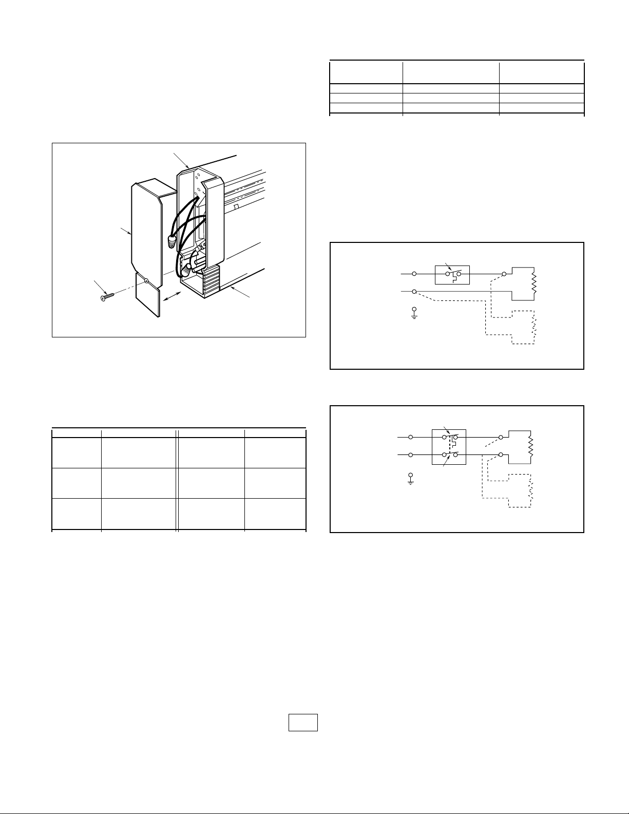
2. Remove selected junction box end cap (Figure 1) and discard; save screw.
3. If the thermostat is controlling more than one heater, the total
of all heater amperage ratings (Table 1) cannot exceed 25
amps at 120 volts A.C. thru 277 volts A.C. Refer to Table 2 for
correct wire, circuit breaker, or fuse sizing.
Table 1
Model Amps Model Amps
500 4.17 1250 10.42
508 2.40 1258 6.01
504 2.08 1254 5.21
507 1.81 1257 4.51
750 6.25 1500 12.50
758 3.61 1508 7.21
754 3.13 1504 6.25
757 2.71 1507 5.42
1000 8.33 2008 9.62
1008 4.81 2004 8.33
1004 4.17 2007 7.22
1007 3.61
Table 2
Minimum AWG Circuit
Wire Size Breaker or
Total Amps (Copper) Fuse Size
0 thru 12 #14 15 Amp
12.1 thru 16 #12 20 Amp
16.1 thru 24 #10 30 Amp
4. Connect thermostat to baseboard heater and power wiring
per wiring diagram using properly sized listed wire nuts.
5. Fold wires back into wiring compartment and install the thermostat assembly in place of the discarded junction box end
cap. Reuse the screw to hold the end cap in place.
6. Reconnect power at main fuse or circuit breaker distribution
panel.
*Single line break thermostats DO NOT have an “OFF” position and will
operate at a temperature below its minimum set point.
Figure 1. Removal of End Cap
1 POLE
2 POLE
JUNCTION
BOX END
CAP
SCREW
JUNCTION BOX
L1
L2
BREAKS ON TEMPERATURE
RISE ONLY*
BLK
GROUND
BLACK OR WHITE
RED
HEATER
HEATER
CAUTION: DO NOT EXCEED
AMPERAGE RATING OF
THERMOSTAT WHEN ADDING
HEATERS.
ADDITIONAL
HEATER(S)
BREAKS IN THE OFF POSITION
AND ON TEMPERATURE RISE
BLK
L1
BLK
L2
GROUND
CAUTION: DO NOT EXCEED
AMPERAGE RATING OF
THERMOSTAT WHEN ADDING
HEATERS.
BREAKS IN THE
OFF POSITION
ONLY
RED
RED
HEATER
ADDITIONAL
HEATER(S)
Page 3

3
SELECTION CHART
Model
Number Description
T1
Single Pole Snap Action Thermostat Assembly.
Rating - 25 Amps at 120V through 277 VAC.
NOTE: Thermostat Comes Assembled to End Cap.
T2
Double Pole Snap Action Thermostat Assembly.
Rating - 25 Amps at 120V through 277 VAC.
NOTE: Thermostat Comes Assembled to End Cap.
T1TPH Same as Model T1 Except Tamperproof Version.
T2TPH Same as Model T2 Except Tamperproof Version.
OPERATION CHECK
1. After your electric baseboard heating system has been completely installed, all thermostats, whether mounted on the
wall or in the baseboard, should be turned to “LOW” or “OFF”.
Then turn on breakers or install fuses. Wait 3 to 5 minutes
and check to see that none of the heaters are operating.
Should any of the heaters be operating, disconnect power
and check your wiring. If none are operating, then turn the
thermostats to the highest position and wait another 3 to 5
minutes. Then check to see that all heaters are in operation.
Should any not be operating, again disconnect power and
check your wiring.
2. Allow entire system to operate steadily for 1/2 hour. This
should remove all residue from manufacturing. (Some smok-
ing may occur).
3. Select the setting for your comfort on all thermostats.
4. Your electric heating system has many advantages, one of
which is zone or room by room control. If you desire to keep
a seldom used room at a lower temperature this may be done
by lowering the thermostat setting and closing the door.
However, DO NOT try to control different rooms at different
temperatures unless the doors are kept closed. This will tend
to increase operating cost and decrease comfort. It is advisable, if rooms are kept open, that all thermostats have the
same setting. By following these instructions you will enjoy
greater comfort.
Page 4

HOW TO ORDER REPAIR PARTS
In order to obtain any needed repair or replacement
parts, warranty service or technical information, please
contact Marley Engineered Products Service Center, 470
Beauty Spot Road East, Bennettsville, SC 29512 USA.
Or, call toll-free 1-800-642-HEAT.
When ordering repair parts, always give the information listed as follows:
1.The Part Number
2.The Model Number
3.The Part Description
4. Date of Manufacture
LIMITED W ARRANTY
All products manufactured by Marley Engineered Products are warranted against defects in workmanship and materials for one
year from date of installation. This warranty does not apply to damage from accident, misuse, or alteration; nor where the connected voltage is more than 5% above the nameplate voltage; nor to equipment improperly installed or wired or maintained in
violation of the product’s installation instructions. All claims for warranty work must be accompanied by proof of the date of installation.
The customer shall be responsible for all costs incurred in the removal or reinstallation of products, including labor costs, and
shipping costs incurred to return products to Marley Engineered Products Service Center.Within the limitations of this warranty,
inoperative units should be returned to the nearest Marley authorized service center or the Marley Engineered Products Service
Center, and we will repair or replace, at our option, at no charge to you with return freight paid by Marley. It is agreed that such
repair or replacement is the exclusive remedy available from Marley Engineered Products.
THE ABOVE WARRANTIES ARE IN LIEU OF ALL OTHER WARRANTIES EXPRESSED OR IMPLIED. AND ALL IMPLIED
WARRANTIES OF MERCHANTABILITY AND FITNESS FOR A PARTICULAR PURPOSE WHICH EXCEED THE AFORESAID
EXPRESSED WARRANTIES ARE HEREBY DISCLAIMED AND EXCLUDED FROM THIS AGREEMENT. MARLEY
ENGINEERED PRODUCTS SHALL NOT BE LIABLE FOR CONSEQUENTIAL DAMAGES ARISING WITH RESPECT TO THE
PRODUCT, WHETHER BASED UPON NEGLIGENCE, TORT, STRICT LIABILITY, OR CONTRACT.
Some states do not allow the exclusion or limitation of incidental or consequential damages, so the above exclusion or limitation
may not apply to you. This warranty gives you specific legal rights, and you may also have other rights which vary from state to
state.
For the address of your nearest authorized service center, contact Marley Engineered Products, in Bennettsville, SC, at 1-800642-4328. Merchandise returned to the factory must be accompanied by a return authorization and service identification tag, both
available from Marley Engineered Products. When requesting return authorization, include all catalog numbers shown on the
products.
Part No. 5200-2092-002 ECR 32417 06/95
4
SPX Corporation
470 Beauty Spot Rd. East
Bennettsville, SC 29512 USA
Page 5

AVERTISSEMENT
Thermostats
Pour Série « D » et à
Caloporteur Liquide
T1 & T2 T1TPH & T2TPH
ACCESSOIRES.
4. ASSUREZ-VOUS QUE LES CARACTÉRISTIQUES
NOMINALES INDIQUÉES SUR LA PLAQUE
SIGNALÉTIQUE DE L’ACCESSOIRE ET DU
RADIATEUR CORRESPONDENT À CELLES DU
RÉSEAU AUQUELILS SONT BRANCHÉS. ASSUREZVOUS QUE LA CHARGE TOTALE COMMANDÉE NE
DÉPASSE PAS LES CARACTÉRISTIQUE
NOMINALES DE L’ACCESSOIRE.
Lisez ce manuel attentivement avant d’installer ou de
faire fonctionner cet appareil. Si vous ne respectez pas
ces instructions, il y a risque de blessures graves et de
dommages. Conservez ce manuel pour consultation
ultérieure.
1. AVANT L’INSTALLATION OU LA MAINTENANCE,
ASSUREZ-VOUS QUE L’ALIMENTATION EST COUPÉE
AU PANNEAU PRINCIPAL DE FUSIBLES OU DE
DISJONCTEURS ET LAISSEZ REFROIDIR LE
RADIATEUR.
2. L’INSTALLATION DOIT ÊTRE CONFORME AUX
EXIGENCES PERTINENTES DES CODES LOCAUX,
DU CODE LE L’ÉLECTRICITÉ ET DES NORMES DU
FOURNISSEUR D’ÉLECTRICITÉ.
3. CONSULTEZ LES INSTRUCTIONS D’INSTALLATION
DU RADIATEUR LORSUQE VOUS INSTALLEZ CES
Cher utilisateur,
Félicitations ! Nous vous remercions d'avoir fait l'acquisition de ce nouveau produit fabriqué par une
division de Marley Engineered Products. Vous avez fait un bon investissement en choisissant un appareil
de qualité imbattable. Veuillez lire attentivement et suivre scrupuleusement les consignes de ce manuel
concernant l'installation et l'entretien. Nous sommes sûrs que vous bénéf icierez de nombreuses années de
confort grâce à cet appareil de chauffage efficace de Marley Engineered Products... le numéro 1 du
secteur du chauffage en matière de conception, fabrication, qualité et service.
... Les employés de
Marley Engineered Products
CONSERVER CETTE NOTICE
Instructions d’installation
Homologué U.L. et C-UL
Dossier E37116
!
Page 6
NOTE: Il n’est pas recommandé d’utiliser plus d’un thermostat
par piece (ou par zone).
INSTALLATION
1. On peut installer le thermostat à l’une ou l’autre des extrémités
du radiateur où est effectué le branchement.
2. Enlevez le couvercle latéral de la boîte de jonction choisie
(voir la figure 1) et mettez-le au rebut. Conservez la vis.
3. Si le thermostat commande plus d’un radiateur, le courant
total des radiateurs ne doit pas dépasser 25 A sous 120 à 277
V c.a. Le tableau 2 indique les valeurs appropriées en ce qui
a trait à la section de conducteur et au courant nominal du
disjoncteur ou du fusible.
Table 1
Modèle Amps Modèle Amps
500 4,17 1250 10,42
508 2,40 1258 6,01
504 2,08 1254 5,21
507 1,81 1257 4,51
750 6,25 1500 12,50
758 3,61 1508 7,21
754 3,13 1504 6,25
757 2,71 1507 5,42
1000 8,33 2008 9,62
1008 4,81 2004 8,33
1004 4,17 2007 7,22
1007 3,61
Table 2
Section Nominale Courant Nominal
Courant AWG (Conducteurs du Disjoncteur ou
Total, A en Cuivre) du Fusible
0 à 12 #14 15 Amp
12,1 à 16 #12 20 Amp
16,1 à 24 #10 30 Amp
4. Reccordez le thermostat au radiateur et aux câbles
d’alimentation selon le schéma de câblage au moyen de
connecteurs tire-bouchon homologués de grosseur
appropriée.
5. Repoussez les conducteurs dans la boîte de jonction et posez
l’ensemble thermostat à la place du couvercle latéral enlevé.
Fixez le nouveau couvercle latéral au moyen de la vis
conservée.
6. Rétablissez l’alimentation au panneau principal de fusibles ou
de disjoncteurs.
Figure 1. Dépose du couvercle latéral.
*Les thermostats unipolaires n’ont pas de position Arrêt (OFF) et peuvent
se déclencher à une température inférieure à celle du réglage minimum.
UNIPOLAIRE
BIPOLAIRE
6
COUVERCLE
LATÉRAL DE
LA BOÎTE DE
JONCTION
VIS
BOÎTE DE JONCTION
RADIATEUR
ATTENTION : LE COURANT TOTAL NE DOIT
PAS DÉPASSER LE COURANT NOMINAL
DU THERMOSTAT LORSQU'ON AJOUTE
DES RADIATEURS.
ATTENTION : LE COURANT TOTAL NE DOIT
PAS DÉPASSER LE COURANT NOMINAL DU
THERMOSTAT LORSQU'ON AJOUTE DES
RADIATEURS.
COUPURE SUR ÉCHAUFFEMENT
SEULEMENT*
NOIR
L1
L2
TERRE
COUPURE SUR ÉCHAUFFEMENT OU
À LA POSITION ARRÊT (OFF)
L1
L2
TERRE
NOIR
NOIR
COUPURE À LA
POSITION
ARRÊT (OFF)
SEULEMENT
NOIR OU BLANC
ROUGE
ROUGE
ROUGE
RADIATEUR
RADIATEURS
ADDITIONELS
RADIATEUR
RADIATEURS
ADDITIONNELS
Page 7

TABLEAU DE SÉLECTION
N° de
Modele Description
T1
Ensemble thermostat unipolaire à rupture brusque
25 A, 120 à 277 V c.a.
NOTE : Le thermostat est fixé au couvercle latéral en
usine.
T2
Ensemble thermostat bipolaire à rupture brusque
25 A, 120 à 277 V c.a.
NOTE : Le thermostat est fixé au couvercle latéral en
usine.
T1TPH Comme T1 mais inviolable.
T2TPH Comme T2 mais inviolable.
VÉRIFICATION DU FONCTIONNEMENT
1. Une fois tous les radiateurs installés, réglez tous les
thermostats (muraux ou intégrés au radiateur) à la position
Bas ou Arrêt. Placez les disjoncteurs à la position Marche ou
posez les fusibles. Attendez 3 à 5 min pour vous assurer
qu’aucun radiateur n’est sous tension. Si un radiateur est sous
tension, coupez l’alimentation et vérifiez les connexions. Si
aucun radiateur n’est sous tension, réglez les thermostats au
maximum et attendez 3 à 5 min. Assurez-vous que tous les
radiateurs sont sous tension. S’il y a un radiateur hors tension,
coupez l’alimentation et vérifiez les connexions.
2. Laissez les radiateurs chauffer de façon continue pendant
environ 1/2 h pour faire évaporer les produits résiduels de
fabrication (cela peut entraîner un léger dégagement de
fumée).
3. Réglez tous les thermostats à la température d’ambiance
désirée.
4. Votre installation de chauffage comporte beaucoup
d’advantages dont le réglage de la température d’ambiance
par pièce ou par zone. Si une pièce est rarement utilisée et
que vous désirez la laisser à une température inférieure, il
suffit de baisser le réglage du thermostat et de fermer la porte.
Par contre, il ne faut pas essayer de régler des pièces
différentes à des températures différentes si on ne garde pas
les portes fermées car cela augmente les coûts de chauffage
et nuit au confort. Si vous gardez les portes des pièces
ouvertes, il est conseillé de régler tous les thermostats à la
même température. Suivez ces instructions pour un confort
optimal.
7
Page 8

ECR 32417 06/95
Part No. 5200-2092-002
COMMENT COMMANDER DES PIÈCES DE
RECHANGE
Afin d'obtenir des pièces détachées ou de remplacement, une
réparation sous garantie ou un renseignement technique, veuillez
contacter Marley Engineered Products Service Center sans frais
en appelant le 1-800-642-HEAT.
Pour commander des pièces détachées, toujours mentionner
les informations indiquées ci-dessous:
1. La référence de la pièce
2. Le numéro du modèle
3. La description de la pièce
4. La date de fabrication
GARANTIE LIMITÉE
Tous les produits mentionnés dans la présente notice sont garantis contre tout vice de matière et de construction pour une durée d'une année à
partir de la date de montage. Cette garantie ne s'applique pas aux dommages provoqués par un accident, une mauvaise utilisation ou une
modification; elle ne s'applique pas non plus lorsque l'appareil a été branché sur un courant de tension supérieure de plus de 5% à la tension
indiquée sur la plaque signalétique, ni à du matériel incorrectement monté, câblé ou entretenu, des instructions de’installation du produit. Toute
réclamation dans le cadre de la garantie doit être accompagnée d'une preuve de la date de montage.
Les frais de démontage et de remontage des produits, y compris de main- d'oeuvre ainsi que les frais d'expédition à un centre de réparation
Marley Engineered Products seront à la charge du client. Retourner, dans les limites de cette garantie, l'appareil en panne, à l'atelier de réparations
agréé Marley le plus proche ou au Centre de réparations Marley Engineered Products et nous le réparerons ou le remplacerons à notre choix,
sans frais pour vous, l'expédition de retour étant à notre charge. Il est entendu que la réparation ou le remplacement constitue le remède exclusif
fourni par Marley Engineered Products.
LES GARANTIES CI-DESSUS REMPLACENT TOUTES LES AUTRES GARANTIES EXPLICITES OU IMPLICITES ET TOUTES LES GARANTIES
IMPLICITES DE QUALITÉ MARCHANDE ET D'ADAPTATION À UN BUT PARTICULIER DÉPASSANT LES GARANTIES EXPLICITES SUSMENTIONNÉES SONT REJETÉES ET EXCLUES DE CE CONTRAT. MARLEY ENGINEERED PRODUCTS NE SERA PAS RESPONSABLE DES
DOMMAGES INDIRECTS PROVOQUÉS PAR LE PRODUIT, QUE LA RÉCLAMATION SE FONDE SUR UNE FAUTE, LA NÉGLIGENCE, LA
STRICTE RESPONSABILITÉ OU LE CONTRAT.
Certains états ne permettent pas les exclusions ou les limites aux dommages indirects ou consécutifs; les exclusions ou limites exposées ci-dessus
risquent donc de ne pas s'appliquer à vous. Cette garantie vous donne des droits spécifiques face à la loi et vous pouvez disposer d'autres droits,
variables d'un état à un autre.
Pour obtenir l'adresse du centre de réparation autorisé le plus proche, appelez Marley Engineered Products à Bennettsville, SC, États-Unis, au 1800-642-4328. Les marchandises retournées à l'usine doivent être accompagnées du numéro d'autorisation et de l'étiquette d'identification du
service,tous deux fournis par Marley Engineered Products. Inclure toutes les références figurant sur les produits dans toute demande d'autorisation
de retour.
SPX Corporation
470 Beauty Spot Rd. East
Bennettsville, SC 29512 USA
8
 Loading...