

Page 1
Accessories
Cat. No. Description
F-PE Pneumatic/Electric Switch. Factory set at 10 psig (69 kPa) to
“make” on pressure drop. May be field wired to “break” on
pressure drop. Pressure set point adjustable to 30 psig
(207 kPa).
F-R2 (24V) Time Delay Relay. 45-60 seconds to close when energized.
F-R12 (120V) Uses 120V or 24V power supply from remote source.
F-TBF T-Bar Frame Kit.
FF-SM Surface Mounting Frame for surface installations.
Painted White.
F-T1 Single pole built-in thermostat kit.
FF-T2 Double pole built-in thermostat kit.
F-TR4 208/240V Primary Transformer/24V Sec. and 24V Holding
Coil Control Relay.
F-TR7 277V Primary Transformer/24V Sec. and 24V Holding Coil
Control Relay.
Installation of Recessed Mounted
Heater in Plaster Ceiling
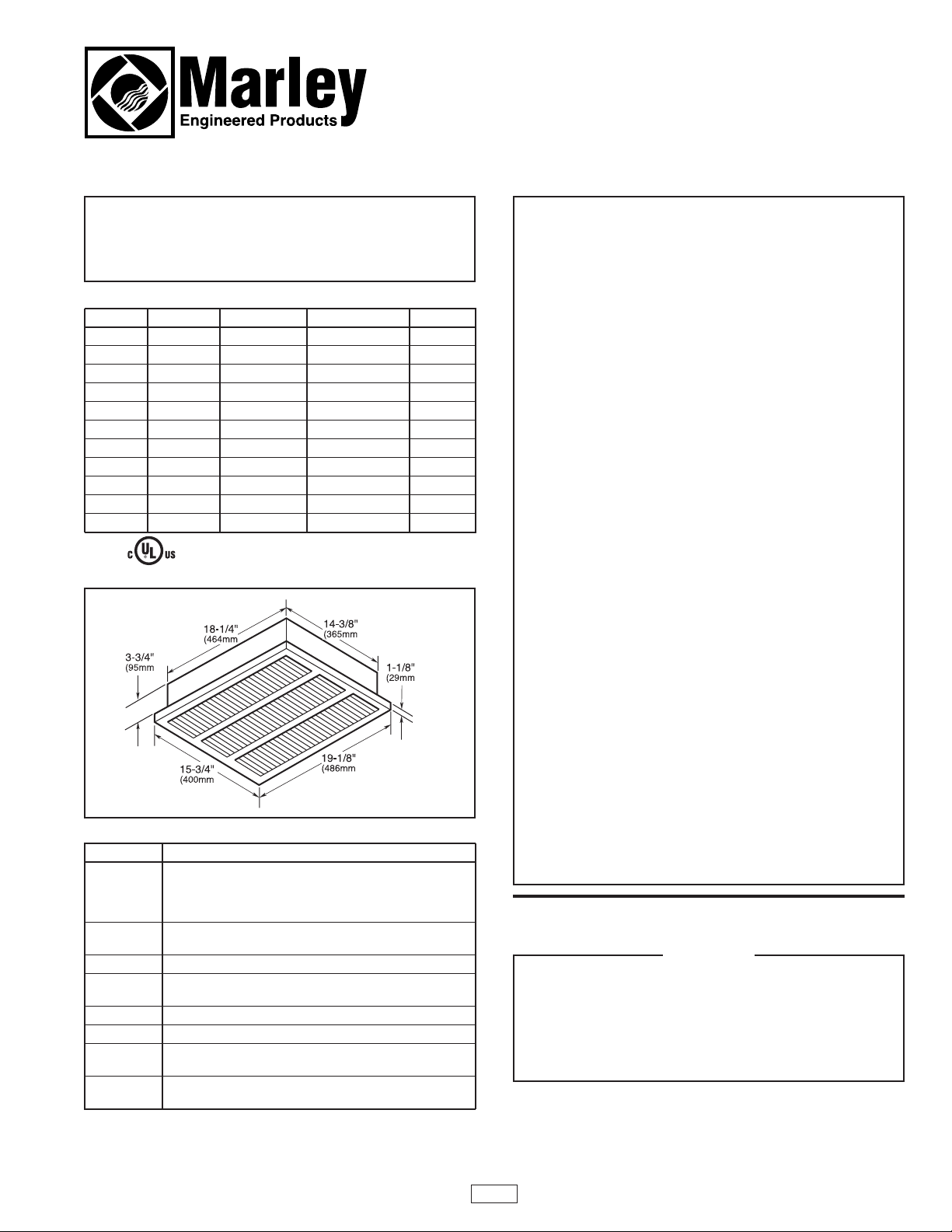
1. Determine the desired mounting location of the heater.
2. Cut a 14-1/2 inch (368mm) by 18-3/8 inch (467mm) hole in
the ceiling for the recessed back box, maintain 12 inch
(305mm) minimum distance between edge of hole and adjacent wall.
WARNING
THIS INSTRUCTION SHEET CONTAINS VITAL INFORMATION
FOR THE PROPER INSTALLATION, USE, AND EFFICIENT
OPERATION OF THE HEATER. CAREFULLY READ THE MANUAL BEFORE INSTALLATION, OPERATION, OR CLEANING OF
THE HEATER. FAILURE TO ADHERE TO THE INSTRUCTIONS
COULD RESULT IN FIRE, ELECTRICAL SHOCK, DEATH, SERIOUS PERSONAL INJURY OR PROPERTY DAMAGE. SAVE
THESE INSTRUCTIONS AND REVIEW FREQUENTLY FOR CONTINUING SAFE OPERATION AND INSTRUCTING FUTURE
USERS.
1. To prevent a possible electrical shock, disconnect all power
coming to heater at main service panel before wiring or servicing.
2. All wiring must be in accordance with the National and Local
Electrical Codes and the heater must be grounded as a precaution against possible electrical shock.
3. Verify the power supply voltage coming to the heater matches the ratings printed on the heater nameplate before energizing.
4. Do not install the heater closer than 12 inches (305mm) to
any wall.
5. Do not operate heater without front cover installed.
6. This heater is hot when in use. To avoid burns, do not let
bare skin touch hot surfaces.
7. Do not insert or allow foreign objects to enter any ventilation
or exhaust openings as this may cause an electric shock, fire,
or damage to the heater.
8. To prevent a possible fire, do not block air intakes or exhaust
in any manner. Keep combustible materials, such as boxes,
crates, etc., away from heater.
9. A heater has hot and arcing or sparking parts inside. Do not
use it in areas where gasoline, paint or flammable liquids are
used or stored.
10. Use this heater only as described in this manual. Any other
use not recommenced by the manufacturer may cause fire,
electric shock, or injury to persons.
11. This heater is not approved for use in corrosive atmospheres
such as marine, green house or chemical storage areas.
Specifications
Cat. No. Volts Watts BTU/Hr. Amps
F-1500 120 1500 51,195 12.5
F-2008 208 2000 6826 9.8
F-2004 240/208 2000/1500 6826/5120 8.3/7.2
F-2007 277/240 2000/1500 6826/5120 7.2/8.2
F-1507 277 1500 5120 5.4
F-4008 208 4000 13,652 19.2
F-4004 240/208 4000/3000 13,652/10,239 16.7/14.4
F-4007 277/240 4000/3000 13,652/10,239 14.4/12.5
F-3007 277 3000 10,239 10.8
F-4804 240/208 4800/3600 16,382/12,287 20.0/17.3
F-4807 277/240 4800/3600 16,382/12,287 17.3/15.0
CONTRACTOR
PLEASE READ AND FOLLOW THESE INSTRUCTIONS. LEAVE INSTALLATION INSTRUCTIONS
FOR USER TO READ.
FAN DELAY NOTE: A fan delay is standard on all units. In order to
have the fan delay operate correctly, separate wiring is required
between the heater and the wall thermostat. See warning, page 2.
RISK OF FIRE - DO NOT INSTALL HEATER CLOSER THAN 12
INCHES (305mm) FROM ANY WALL.
RISK OF FALLING - THE HEATER BACK BOX MUST BE
SECURELY MOUNTED TO THE BUILDING STRUCTURE AND
THE BUILDING STRUCTURE MUST BE CAPABLE OF SUPPORTING THE HEATER WITH ALL ACCESSORIES. THE
HEATER WEIGHT IS AT LEAST 20 POUNDS (9 kg).
WARNING
Installation Instructions
and
RENEWAL PARTS IDENTIFICATION
“F” Series
Ceiling Mounted Fan-Forced Heater
1
FILE #E21609
Page 2
3. Bring the power supply cable to the heater location providing
at least 12 inches (305mm) of cable for wiring.
4. Remove front cover and heater assembly from carton.
NOTE: Screws to mount the front cover are packed sepa-
rately in an envelope. The kit contains four standard cross
recess screws and four spanner head screws in case tamper resistance is required.
5. Remove the heater assembly and disconnect switch assem-
bly from the back box.
6. Remove the desired knockout from the back box in the area
behind the disconnect switch, install cable clamp and bring
power supply cable into box leaving at least six inches of
cable in box for wiring.
7. Fit heater back box into hole in ceiling and secure in position
using mounting holes in side of back box with four fasteners
(not provided). See WARNING at beginning of this section.
8. If there are any accessories to be installed with this heater,
these should be installed at this time. Refer to the instructions provided with the accessories.
9. Remove the wiring compartment cover from heater assem-
bly by removing two screws. Mount the heater to the back
box using four screws previously removed in step 5.
10. Attach the supply ground conductor to the green colored
screw in the heater back box.
11. Connect the power supply lead wires to the blue colored
lead wires on the disconnect switch using appropriately
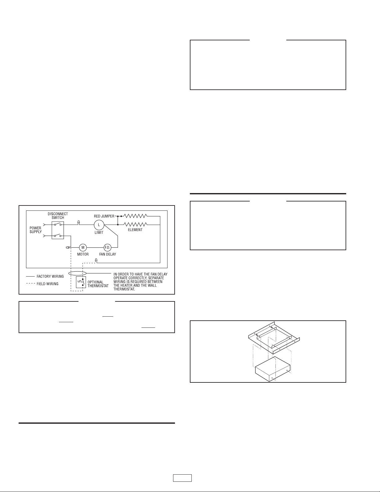
sized wire connectors. See Wiring Diagram, Figure 1.
12. Feed the heater (or accessory if provided) lead wires
through the smooth hole in the disconnect switch bracket
and connect these leads to the black colored lead wires
from the disconnect switch using appropriately sized wire
connectors.
13. Carefully bundle lead wires under disconnect switch brack-
et and secure bracket to back box using two screws
removed in step 5.
14. Install the wiring compartment cover removed in step 9.
Push the disconnect switch to the “ON” position.
15. Install the front cover using the four standard cross recess
or the spanner tamper resistant screws provided with the
heater.
Installation of Heater Using the Cat. No. F-SM
Surface Mounting Frame
1. Determine the desired location for the heater.
2. Follow steps 3, 4, 5, and 6 of the “Installation of Recessed
Mounted Heater in Plaster Ceiling” instructions.
NOTE: The power supply cable must be routed between
the heater back box and the surface mounting frame.
3. Mount the back box to the ceiling using mounting holes in
the back of the back box and four fasteners (not provided).
See WARNING above.
4. Fit the Cat. No. F-SM Surface Mounting Frame over the
back box and secure in place with the two screws provided
in kit.
5. Complete the installation by following steps 8 through 15 of
the “Installation of Recessed Mounted Heater in Plaster Ceiling” instructions.
Installation of Heater in T-Bar Ceiling
Using the Cat. No. F-TBF Kit
1. Determine the desired location for the heater.
2. Remove heater from carton, remove front cover, heater
assembly and disconnect switch from back box as described
in steps 4 and 5 of the “Installation of Recessed Mounted
Heater in Plaster Ceiling” instructions.
3. Mount the heater back box to the F-TBF kit frame using the
four screws provided with kit. See Figure 2.
4. Place the F-TBF frame with heater back box installed in ceil-
ing framing and secure in position. Secure the frame to the
building structure as necessary using appropriate wire to
prevent the heater and frame from falling.
5. Bring power supply cable to heater location, remove the
desired knockout in back box and install cable using an
appropriate cable clamp, leaving at least six inches (150mm)
of wire in box for connections.
NOTE: Power supply cable must enter back box in location behind the disconnect switch assembly.
6. Complete the installation by following steps 8 through 15 of
the “Installation of Recessed Mounted Heater in Plaster Ceil-
ing” instructions.
RISK OF FIRE - DO NOT INSTALL HEATER CLOSER THAN 12
INCHES (305mm) FROM ANY WALL.
RISK OF FALLING - THE HEATER BACK BOX MUST BE
SECURELY MOUNTED TO THE BUILDING STRUCTURE AND
THE BUILDING STRUCTURE MUST BE CAPABLE OF SUPPORTING THE HEATER WITH ALL ACCESSORIES. THE
HEATER WEIGHT IS AT LEAST 20 POUNDS (9 kg).
WARNING
TO REDUCE RISK OF FIRE OR PERMANENT DAMAGE TO
HEATER, THERMOSTAT MUST NOT CUT POWER TO FAN.
THERMOSTAT MUST BE WIRED AS SHOWN IN WIRING DIAGRAM SO THAT IT CYCLES HEATING ELEMENTS ONLY.
WARNING
Figure 1
Figure 2
2
RISK OF FIRE - DO NOT INSTALL HEATER CLOSER THAN 12
INCHES (305mm) FROM ANY WALL.
RISK OF FALLING - THE HEATER BACK BOX MUST BE
SECURELY MOUNTED TO THE BUILDING STRUCTURE AND
THE BUILDING STRUCTURE MUST BE CAPABLE OF SUPPORTING THE HEATER WITH ALL ACCESSORIES. THE
HEATER WEIGHT IS AT LEAST 20 POUNDS (9 kg).
WARNING
Page 3

Heater Check-Out and Operation
1. Turn the thermostat that is provided to control the heater to
the full counter-clockwise direction (LO or OFF setting).
2. Turn power to heater ON at main service panel.
3. Check heater to confirm it is not operating.
4. Turn thermostat to the full clockwise positon (HI setting).
This should energize the heater. In a short time, the fan
should come on and warm air should flow from the heater.
NOTE: This heater is provided with a fan delay control that
allows the heating element to warm prior to the fan coming
on. This delay will also allow the fan to operate for a short
period after the heating element has been turned off to
remove the residual heat from the heater.
5. After the room has reached the desired temperature, adjust
the thermostat back to the desired temperature setting. In a
short time, the fan should turn off.
NOTE: For the best results, the heater should be left “ON”
constantly during the heating season as the thermostat,
when properly set, will maintain the desired temperature.
Maintenance and Cleaning
Maintenance
Your heater is designed for years of trouble-free operation and
requires no special maintenance other than occasional cleaning. The motor is permanently lubricated.
Cleaning
Once each year, the heater should be cleaned to remove dust
and other foreign material which has collected during the heating season, as follows:
1. Turn power off at main switch.
2. Remove grille by removing four screws and turn disconnect
switch to the “OFF” position.
3. Use vacuum cleaner with brush attachment to remove dust
and dirt that has accumulated in heater (especially around
heating element and fan blade). Do not use water or any
cleaners to clean heater components.
4. After cleaning, turn disconnect switch to the “ON” position.
5. Replace grille.
6. Wipe grille clean with a damp cloth. DO NOT use waxes or
any cleaners that leave a residue since these may discolor
during heater operaton.
7. Turn the main line switch on at the switch panel to restore
power to heater. The heater is now ready for another season
of operation.
Ref. No. Description Part Number
1 Back Box 1203-2015-000
2 Front Cover 1402-2149-000
3 Motor, 208V 3900-2010-000
3 Motor, 240/277V 3900-2010-001
3 Motor, 120V 3900-2010-003
4 Fan Panel 4513-2042-000
5 Motor Mount 310914002
6 High Limit 410169001
7 Fan Delay 410074000
8 Disconnect Switch 410170001
9 Disconnect Switch Bracket 1215-2058-000
10 Element-1500W, 120V 302012827
Ref. No. Description Part Number
10 Element-1500W, 277V 302015006
10 Element- 2000W, 208V 302015001
10 Element- 2000W, 240V 302015002
10 Element- 2000W, 277V 302015003
10 Element- 3000W, 277V 302012006
10 Element- 4000W, 208V 302012007
10 Element- 4000W, 240V 302012008
10 Element- 4000W, 277V 302012009
10 Element- 4800W, 240V 302012010
10 Element- 4800W, 277V 302012011
11 Fan Blade 490030103
12 Wire Compartment Cover 4513-2037-000
NOTE: Always order by “Part Number”, never by “Ref. No.”
Renewal Part Indentificaiton
3
1
5
3
11
10
7
6
9
8
12
4
2
Page 4

LIMITED WARRANTY
All products covered by this instruction sheet are warranted against defects in workmanship and materials for one year from date of installation,
except heating elements which are warranted against defect in workmanship and material for five years from date of installation. This warranty does
not apply to damage from accident, misuse, or alteration; nor where the connected voltage is more than 5% above the nameplate voltage; nor to
equipment improperly installed or wired or maintained in violation of this instruction sheet. All claims for warranty work must be accompanied by proof
of the date of installation.
The customer shall be responsible for all costs incurred in the removal or reinstallation of products, including labor costs, and shipping costs incurred
to return products to a Marley Engineered Products Service Center. Within the limitations of this warranty, inoperative units should be returned to the
nearest Marley authorized service center, or the Marley Engineered Products Service Center, and we will repair or replace; at our option, at no
charge to you with return freight paid by Marley. It is agreed that such repair or replacement is the exclusive remedy available from Marley Engineered Products.
THE ABOVE WARRANTIES ARE IN LIEU OF ALL OTHER WARRANTIES EXPRESSED OR IMPLIED, AND ALL IMPLIED WARRANTIES OF
MERCHANTABILITY AND FITNESS FOR A PARTICULAR PURPOSE WHICH EXCEED THE AFORESAID EXPRESSED WARRANTIES ARE
HEREBY DISCLAIMED AND EXCLUDED FROM THIS AGREEMENT. MARLEY ENGINEERED PRODUCTS SHALL NOT BE LIABLE FOR CONSEQUENTIAL DAMAGES ARISING WITH RESPECT TO THE PRODUCT, WHETHER BASED UPON NEGLIGENCE, TORT, STRICT LIABILITY
OR CONTRACT.
Some states do not allow the exclusion or limitation of incidental or consequential damages, so the above exclusion or limitation may not apply to
you. This warranty gives you specific legal rights and you may also have other rights which vary from state to state.
For the address of your nearest authorized service center contact Marley Engineered Products, 470 Beauty Spot Road East, Bennettsville, South
Carolina 29512 USA. Merchandise returned to the factory must be accompanied by a return authorization and service identification tag, both available from the above location. When requesting return authorization, include all catalog numbers shown on the products.
5200-2146-003 PPD 058
02/06
4
HOW TO OBTAIN WARRANTY SERVICE AND
WARRANTY PARTS PLUS GENERAL INFORMATION
1. Warranty Service or Parts 1-800-642-4328
2. Purchase Replacement Parts 1-800-654-3545
3. General Product Information www.marleymep.com
Note: When obtaining service always have the following:
1. Model number of the product
2. Date of manufacture
3. Part number or description
470 Beauty Spot Rd. East
Bennettsville, SC 29512 USA
 Loading...