

Page 1
N Series
!
Overhead Infrared
Heaters
Installation & Maintenance Instructions
Dear Owner,
Congratulations! Thank you for purchasing this new heater by Marley Engineered Products. You have made a wise investment selecting the highest quality product in the heating industry. Please carefully read the installation and maintenance
instructions shown in this manual. You should enjoy years of efficient heating comfort with this product from Marley
Engineered Products... the industry’s leader in design, manufacturing, quality and service.
... The Employees of
Marley Engineered Products
WARNING
Read Carefully - This instruction sheet contains vital infor-
mation for the proper installation, use and efficient operation of the heater. Carefully read the manual before installation, operation, or cleaning of the heater. Failure to adhere
to the instructions could result in fire, electric shock, death,
serious personal injury or property damage. Save these
instructions and review frequently for continuing safe operation and instructing future users.
RISK OF FIRE, ELECTRICAL SHOCK OR FALLING:
1. To prevent electrical shock, disconnect all power coming to heater at main service panel before wiring or servicing.
2. All wiring must be in accordance with the National and
Local Electrical Codes and the heater must be grounded as a precaution against possible electric shock.
3. Verify the power supply voltage coming to heater
matches the ratings printed on the heater nameplate
before energizing.
4. This heater is NOT suitable for use in hazardous locations as described by the National Fire Protection
Association (NFPA). This heater has hot and arcing or
sparking parts inside. DO NOT use in areas where
gasoline, paint or other flammable liquids or stored.
5. Do not use this heater in areas where corrosive agents
such as
Muriatic Acid • Ethylene Dichloride (Mastics-Glues-Adhesives)
• Chlorine • Chlorides • Fluorides • Perchlorethylene •
Trichlorethylene • Hydrochloric Acid • Halogenated
Hydrocarbons • Industrial Caustics.
6. This heater is intended for ceiling installation ONLY. The
following clearances MUST be maintained:
a) Top of heater to ceiling - 3 in (76 mm).
b) Bottom of heater to floor - 10 ft (3048 mm).
c) Side of heater to wall - 12 in (305 mm).
d) End of heater to wall - 12 in (305 mm).
e) Side of heater to side of adjacent heater - 36 in
f) End of heater to end of adjacent heater - 36 in (914
7. Heater MUST be securely fastened to the building
structure to prevent it from falling.
8. DO NOT stack or store combustible materials in the
radiation path under the heater. At least 5 feet (1524
mm) clearance MUST be maintained between bottom
of heater and combustibles stored.
9. Do NOT use as a residential or household heater.
Ammonia • Carbon tetrachloride • Sulphuric acid •
(914 mm).
mm).
SAVE THESE INSTRUCTIONS
Page 2
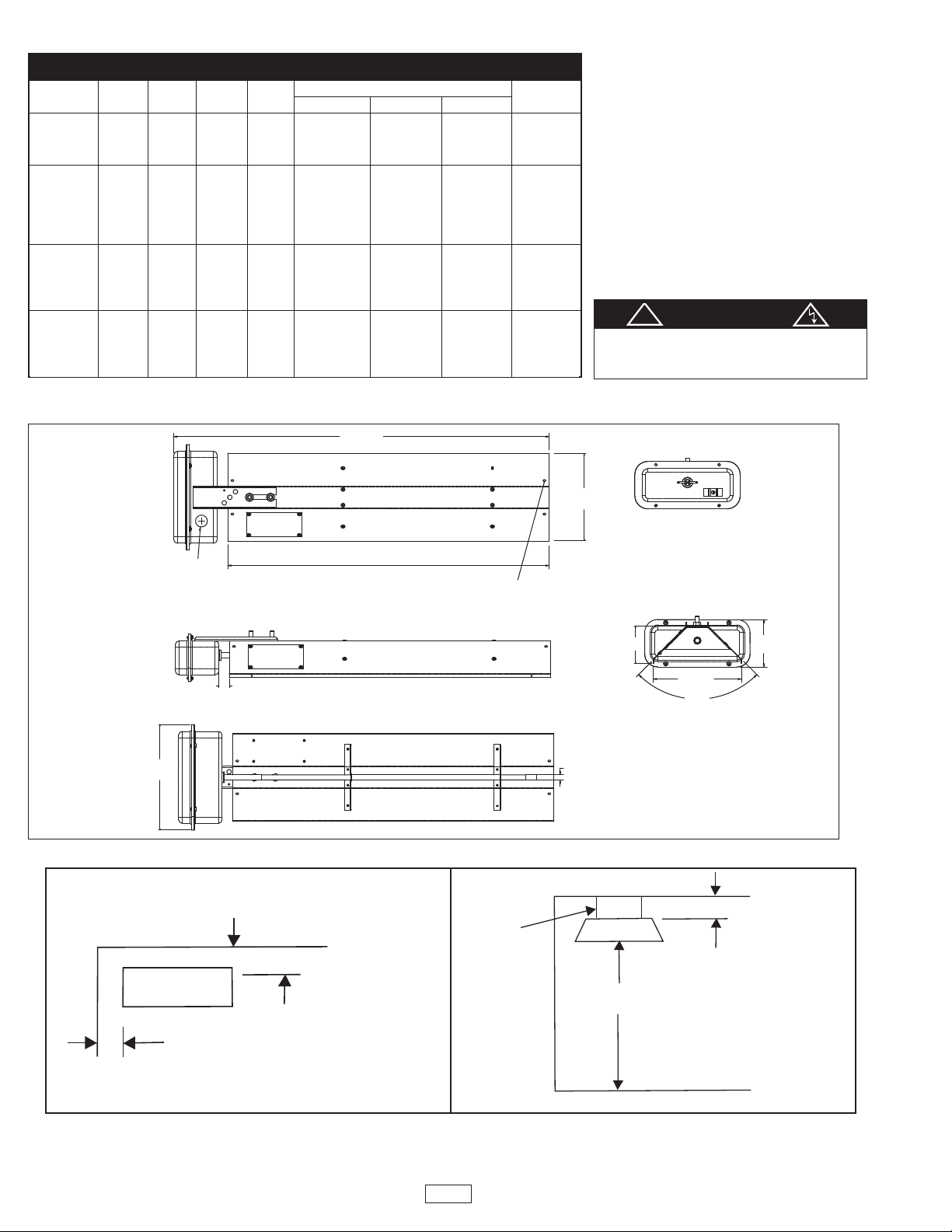
SPECIFICATIONS
Ø1.125
SERVICE
ENTRANCE
OPENING
4X1/4" Ø MOUNTING
HOLE FOR "S" HOOKS
1.000±.062
(3.500)
90˚
(8.375)
(4.500)
(10.000)
Ø.475
VIEW SHOWN WITH
COVER REMOVED
("B")
("A")
TOP VIEW
Heater
Wall
Wall
12" (304.8mm) Min.
12" (304.8mm) Min.
SIDE VIEW
H
Wall
Floor
Ceiling
Chain
1
3" (76.2mm) Min.
10' (3048mm) Min.
!
Model Dimensions Wire Ga.
Number Volts Watts Amps BTU A Length B Width D Depth (Min.)
N1011B 120 8.3
N1081B 208 4.8 27.125” 8.375” 3.5”
N1021B 240 1000 4.2 3412 (689 mm) (212 mm) (88.9) 14 Ga.
1511B 120 12.5
N
N1581B 208 7.2 35.625” 8.375” 3.5”
N1521B 240 1500 6.3 5118 (905 mm) (212 mm) (88.9) 14 Ga.
N1571B 277 5.4
N1531B 347 4.3
N2001B 208 9.6
N2021B 240 2000 8.3 6824 46.625” 8.375” 3.5” 14 Ga.
2071B 277 7.2 (1184 mm) (212 mm) (88.9)
N
N2031B 347 5.8
N2501B 208 12.0
N2521B 240 2500 10.4 8530 53.375” 8.375” 3.5” 14 Ga.
N2571B 277 9.0 (1356 mm) (212 mm) (88.9)
N2531B 347 7.2
INSTALLATION
The Marley Engineered Products
N Series radiant heater is shipped fully
assembled. The heater can be hung from
the ceiling by chains or rigid angle brackets
attached to the heater
rackets located on the back of the heater.
b
Hanging chain kits are available for these
heaters that will allow for installations to 6
feet from the ceiling.) (Model MHK)
Minimum spacings:
Ceiling to top of heater is 3 in.
Wall to sides of heater is 12 in.
loor to bottom of heater is 10 feet.
F
CAUTION
Installer should consult state and local
codes and meet any applicable
requirements regarding the installation.
a
Figure 1
Figure 2
2
Page 3

WIRING
!!!
a
WARNING
ELECTRIC SHOCK HAZARD. Disconnect all power before
installing or servicing heater. Failure to do so could result in
personal injury or property damage. Heater must be
ffectively grounded in accordance with the National Electrical
e
Code, NFPA 70.
WARNING
All electrical wiring must be done by a qualified person in
accordance with National Electrical Code (NEC) and meet all
tate and local regulations.
s
1. Use heater only at the voltage specified on the nameplate.
2. Branch circuit wire for connection to heater must be at least
90°C wire. Use copper conductors only.
3. The heater connection points are located in the gasketed
terminal enclosure. To remove cover, remove 4 screws on
the cover. Remove the cover to expose wiring connection
points.
4. A green ground terminal is provided in the bottom of the
enclosure. The ground wire should be connected before
other connections are made.
5. Refer to Table 1 for proper entrance wiring size.
6. Heater can be wired with rigid or flexible conduit.
Grill Kit Selection Guide
Model Volts Watts Optional Grill Kit
N1011B 120 1000
N1081B 208 1000 NWG01
N1021B 240 1000
N1511B 120 1500
N1581B 208 1500
N1521B 240 1500 NWG105
N1571B 277 1500
N1531B 347 1500
N2001B 208 2000
N2021B 240 2000
N2071B 277 2000
N2031B 347 2000
N2501B 208 2500
N2521B 240 2500
N2571B 277 2500
N2531B 347 2500
NWG200
NWG250
MAINTENANCE
WARNING
a
ELECTRIC SHOCK HAZARD. Disconnect all power before
servicing or replacing heating elements.
The reflectors should be kept clean to obtain the maximum
radiant output.
a
Element Replacement
1. Remove Terminal Box Cover.
. Disconnect lead wires from heater terminals and disengage
2
box from conduit /cable fitting.
3. Remove safety grills (if installed).
4. Loosen (2) 3/8” nuts from the terminal box bracket located on
the back of the heater and slide the entire heating element
assembly out of the reflector assembly.
5. Remove bulkhead fitting nut and washers.
6. Remove failed element and replace with a new element.
7. Place gasket on the bulkhead fitting and insert terminals and
fitting into the element hole in the terminal box.
8. Place washer and nut on the bulkhead fitting and tighten.
9. Reassemble by following the reverse procedures (steps 4
through 1)
Replacement Parts
Model Volts Watts Element
N1011B 120 1000 322-074905-143
N1081B 208 1000 322-074905-144
N1021B 240 1000 322-074905-145
N1511B 120 1500 322-074905-148
N1581B 208 1500 322-074905-149
N1521B 240 1500 322-074905-150
N1571B 277 1500 322-074905-151
N1531B 347 1500 322-074905-152
N2001B 208 2000 322-074905-153
N2021B 240 2000 322-074905-154
N2071B 277 2000 322-074905-155
N2031B 347 2000 322-074905-156
N2501B 208 2500 322-074905-157
N2521B 240 2500 322-074905-158
N2571B 277 2500 322-074905-159
N2531B 347 2500 322-074905-160
Hanging Kit for All Models: MHK
3
Page 4

All products manufactured by Marley Engineered Products are warranted against defects in workmanship and materials for one year from date of
LIMITED WARRANTY
installation. This warranty does not apply to damage from accident, misuse, or alteration; nor where the connected voltage is more than 5% above the
nameplate voltage; nor to equipment improperly installed or wired or maintained in violation of the productʼs installation instructions. All claims for warranty work must be accompanied by proof of the date of installation.
The customer shall be responsible for all costs incurred in the removal or reinstallation of products, including labor costs, and shipping costs incurred
to return products to Marley Engineered Products Service Center.Within the limitations of this warranty, inoperative units should be returned to the
nearest Marley authorized service center or the Marley Engineered Products Service Center, and we will repair or replace, at our option, at no charge
to you with return freight paid by Marley. It is agreed that such repair or replacement is the exclusive remedy available from Marley Engineered
Products.
THE ABOVE WARRANTIES ARE IN LIEU OF ALL OTHER WARRANTIES EXPRESSED OR IMPLIED, AND ALL IMPLIED WARRANTIES OF MERCHANTABILITY AND FITNESS FOR A PARTICULAR PURPOSE WHICH EXCEED THE AFORESAID EXPRESSED WARRANTIES ARE HEREBY
DISCLAIMED AND EXCLUDED FROM THIS AGREEMENT. MARLEY ENGINEERED PRODUCTS SHALL NOT BE LIABLE FOR CONSEQUENTIAL
DAMAGES ARISING WITH RESPECT TO THE PRODUCT, WHETHER BASED UPON NEGLIGENCE, TORT, STRICT LIABILITY, OR CONTRACT.
Some states do not allow the exclusion or limitation of incidental or consequential damages, so the above exclusion or limitation may not apply to you.
This warranty gives you specific legal rights, and you may also have other rights which vary from state to state.
For the address of your nearest authorized service center, contact Marley Engineered Products in Bennettsville, SC, at 1-800-642-4328. Merchandise
returned to the factory must be accompanied by a return authorization and service identification tag, both available from Marley Engineered Products.
When requesting return authorization, include all catalog numbers shown on the products.
HOW TO OBTAIN WARRANTY SERVICE AND
WARRANTY PARTS PLUS GENERAL INFORMATION
1. Warranty Service or Parts 1-800-642-4328
2. Purchase Replacement Parts 1-800-654-3545
3. General Product Information www.marleymep.com
Note: When obtaining service always have the following:
1. Model number of the product
2. Date of manufacture
3. Part number or description
Part No. 5200-2649-001
ECR 38770
06/10
4
470 Beauty Spot Rd. East
Bennettsville, SC 29512 USA
 Loading...