

Page 1
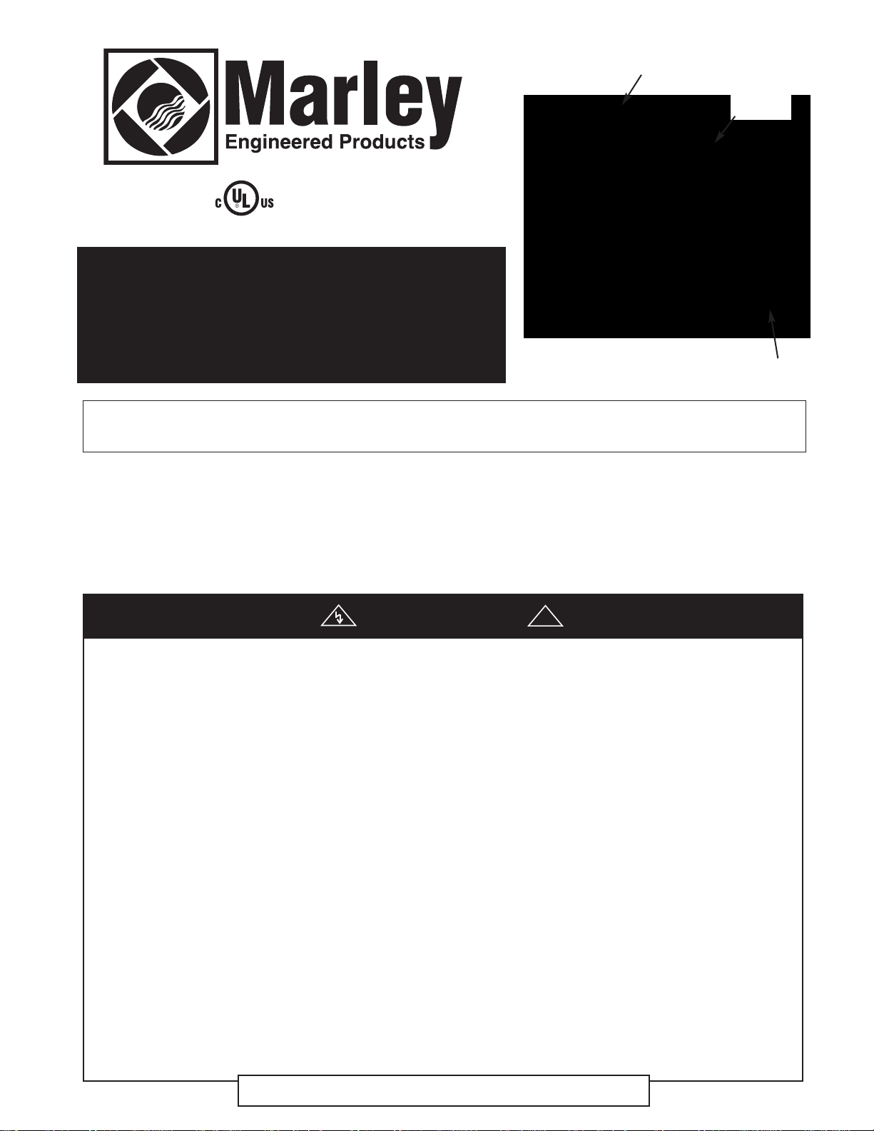
C Series
B Model
BACK BOX
HEATER
ASSEMBLY
Fan-Forced Wall Heaters
Clip’n’Fit®Board
US Patent No. 6,172,343
with
FRONT COVER
Installation & Maintenance Instructions
Dear Owner,
Congratulations! Thank you for purchasing this new heater manufactured by Marley Engineered Products. You have made
a wise investment selecting the highest quality product in the heating industry. Please carefully read the installation and
maintenance instructions shown in this manual. You should enjoy years of efficient heating comfort with this product from
Marley Engineered Products... the industry’s leader in design, manufacturing, quality and service.
... The Employees of Marley Engineered Products
WARNING
Read Carefully - These instructions are written to help you prevent
difficulties that might arise during installation of heaters. Studying
the instructions first may save you considerable time and money
later. Observe the following procedures, and cut your installation
time to a minimum. CAUTION - TO REDUCE RISK OF FIRE AND
ELECTRIC SHOCK:
1. Disconnect all power coming to heater at main service panel
before wiring or servicing.
2. All wiring must be in accordance with the National and Local
Electrical Codes and the heater must be grounded.
3. Verify the power supply voltage coming to heater matches the
ratings printed on the heater nameplate before energizing.
4. This heater is hot when in use. To avoid burns, do not let bare
skin touch hot surfaces.
5. Do not insert or allow foreign objects to enter any ventilation or
exhaust opening as this may cause an electric shock, fire, or
damage to the heater.
6. Grille and discharge air are hot when in use. Do not install or use
heater in any area where airflow from heater may be blocked or
obstructed. Do not install behind doors, furniture, towel racks,
curtains, or boxes. Hot air may damage certain fabrics and plastics. Always keep electrical cords, beddings, crates, drapes, and
other combustibles away from heater. Do not install heater in
ceiling.
7. A heater has hot and arcing or sparking parts inside. Do not use
it in areas where gasoline, paint, or flammable liquids are used
or stored.
8. Use this heater only as described in this manual. Any other use
not recommended by the manufacturer may cause fire, electric
shock, or injury to persons.
9. This heater is not approved for use in corrosive atmospheres
such as marine, green house, or chemical storage areas.
10. When wall mounted, heater must only be installed in a vertical
direction (motor below element) as shown in this manual. Do not
install sideways, upside down.
11. Heater must be installed with CBB (Type CO2-BB) Back Box.
12. The following minimum clearances must be maintained:
• Wall Mounting:
• Ceiling Mounting (Max 1000 Watts)
13. When wiring, power supply must enter through knockouts in left
side of back box. Do not use the knockouts in right side back
box. Refer to Fig. 1.
To determine which side is left or right:
1.) Orient the back box so the “TOP” marking and arrows are
visible and upright; and 2.) Ensure that the fan deck is oriented
with the element side on the “TOP” side of the back box.
14. Do not operate heater without grille installed.
15. Do not use heater for dry out. Paint, plaster, sawdust, and drywall sanding dust will damage heater and must be kept out of
heater.
16. Keep heater clean. See maintenance and cleaning instructions
on page 3.
!
Heater to floor - 4.5 in. (114 mm)
Heater to adjacent wall - 4.5 in. (114 mm)
Heater to ceiling - 12 in. (305 mm).
Heater to any wall - 12” (305mm)
SAVE THESE INSTRUCTIONS
Page 2
Wall Mounted
LAMP
R
M
ELEMENT
TCO
LIMIT
CONTROL
MOTOR
CLIP'N'FIT
®
2
1
3
RED
JUMPER
BLUE
JUMPER
REMOTE 1
POL E T'STAT
BLACK
RED
REMOTE OR
OPTIONAL 2
PO LE T'S TAT
BLACK
RED
L1
L2/N
!
GENERAL
•The C series heaters are designed for recessed installation in 2 X 4 stud or
larger wall using the model CBB (Type CO2-BB) back box. The heater may
be wired using standard building (60 degrees C minimum) wire.
•The optimum mounting height for this heater is 18” to 24” (457mm to
610mm) from floor to bottom of back box. In any case, do not install closer
than 4.5” (114mm) from the floor or adjacent wall.
Ceiling Mount
•The C Series heaters are designed for ceiling mount provided the wattage
does not exceed 1000 watts. In order for your heater to be rated for
ceiling application, the heater must
be trimmed back to 1000 watts or less.
(See Change Wattage Output below)
•The optimum clearances to any wall surface are 12 inches. Do not mount
heater in the ceiling if these clearances are not met.
•Ceiling heaters can be recessed or surfaced mounted.
Heaters are also approved for semi-recessed or surface mounting on walls. Refer to
instructions for installations of the CSM Surface Mounting frame.
INSTALLATION OF BACK BOX
IN NEW CONSTRUCTION
NOTE: If the finished wall surface is already up, follow instructions for
“INSTALLATION OF BACK BOX IN EXISTING CONSTRUCTION”.
1. Allow for the thickness of the finished surface when installing the back
box. The edge of the back box must be installed flush with the finished
surface. Markings on the side of the back box for 1/2” or 5/8” finishing
wall are provided.
BEND
OUT
TAB
CABLE CLAMP
LEAD
HOLES
BACK BOX
Figure 1
NAILS OR
SCREWS
SUPPLY
WIRING
CABLE
2. Determine which side of the back box is to be mounted against a stud or
joist and bend the tabs at the rear corners out 90 degrees so that the
back box will be square with the stud after installation.
3. Remove one of the knockouts on left side of the back box and install a
cable or conduit connector. (See warning 13)
4. Position back box against side with studs or ceiling joist and secure with
nails or screws as shown in Figure 1.
NOTE: The back box must be installed to a wall stud or ceiling joist and
secured using nails or screws as shown in Figure 1.
5. Run power supply cable through the connector, leaving about 6” of wire
inside the box.
6. Connect the supply cable ground wire to green ground wire provided.
NOTE: Lead holes for a #8 sheet metal screw have been provided in the sides
of the back box. After the finished wall or ceiling has been put up, drive a
#8(m4) sheet metal screw (recommended 1”(25mm) long) through the side of
the box not mounted to the stud. This will prevent the back box from pulling
out when installing the heater assembly. (See Figure1)
INSTALLATION OF BACK BOX
IN EXISTING CONSTRUCTION
1. The edge of the back box must be installed flush with the finished surface.
Determine which side of the back box is to be mounted against a stud or joist
and bend the tabs at the rear corners out 90 degrees so that the back
box will be square with the stud after installation. (See Figure 1).
2. Carefully cut a hole measuring 9-3/8”(239mm) wide by 11-1/8”(284mm)
long. One edge of the hole must be cut along edge of the wall stud.
3. Bring power supply cable to heater mounting location leaving at least
10”(255mm) of cable for wiring.
4. Remove desired knockout on left side of back box.
5. Install cable clamp to cable and install into back box, leaving at least
6”(152mm) of cable in box for wiring.
6. Connect the supply cable ground wire to green ground wire provided.
7. Fit back box into mounting hole in wall by first inserting cable end of box then
rotating box into position.
8. Secure box to wall stud or ceiling joist using nails or screws.
CAUTION
TO PREVENT POSSIBLE WIRING DAMAGE CUT EXCESS SUPPLY
WIRE INSIDE BACKBOX TO PROVIDE APPROXIMATELY 6 INCHES
FOR CONNECTION TO HEATER LEADS. AFTER CONNECTIONS ARE
MADE, MAKE SURE CONNECTIONS ARE TIGHT AND ALL WIRING IS
POSITIONED AWAY FROM FAN BLADE AND HEATING ELEMENT.
NOTE: Lead holes for a #8 sheet metal screw have been provided in the sides
of the back box. After the finished wall or ceiling has been put up, drive a #8(m4)
sheet metal screw (recommended 1”(25mm) long) through the side of the box
not mounted to the stud.(joist) This will prevent the back from pulling out when
installing the heater assembly. (See Figure 1)
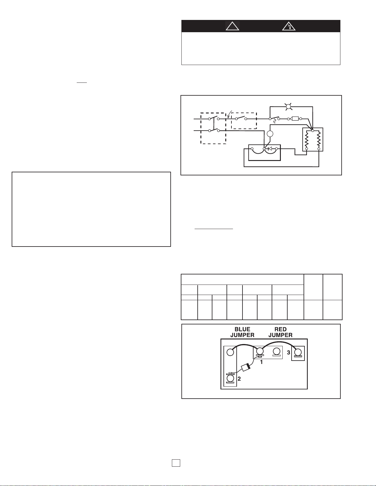
Figure 2 Wiring Diagram
NOTE: Heaters are factory wired per nameplate, voltage and wattage. Refer to
Table1, page 3 for details. See “TO CHANGE WATTAGE OUTPUT” section if
lower wattage is desired and make change before installating heat deck.
INSTALLATION AND WIRING
1. Following wiring diagram (Figure 2) connect supply wires to heater lead-
wires in back box using appropriate wire connectors.
NOTE: For 120 volt heaters connect the white neutral supply lead to the heater’s white
or red with white flag marker pigtail lead, and connect the black supply lead to the black
pigtail lead.
2. Secure supply ground wire under green ground screw in back box (or
green ground wire if provided).
3. Fit heater/fan assembly into back box making sure all wiring is powitioned
away from fan and heating element.and secure in place with (2) screws
provided through the center slots in the sides of the fan assembly.
OF HEATER / FAN ASSEMBLY
WATTAGE
C1512IF C2024IF C2224IF Jumper 1 Jumper 2
C1512T2 C1524T2 C2028IF C2024T2 C2224T2 Blue Red
@120V @208V @240V @208V @208V @240V @208V @240V Jumper Jumper
1500 1125 1500 2000 1500 2000 1688 2250 Leave In Leave In
1125 844 1125 1500 1125 1500 1266 1688 Clip Out Leave In
750 563 750 1000 750 1000 844 1125 Leave In Clip Out
375 281 375 500 375 500 422 563 Clip Out Clip Out
Figure 3 Clip’n’Fit®Board
The chart below shows the wattages available by model. Each heater is factory wired for its maximum wattage. The last two columns in the chart refer to the
jumpers on the CLIP’n’FIT
jumper 2 as shown in the chart below. Completely remove jumpers by clipping
at both ends as close to the board as possible.
2
TO CHANGE WATTAGE OUTPUT
®
Board. To change wattage, clip out jumper 1 and/or
Page 3
INSTALLATION OF FRONT COVER (GRILLE) AND
THERMOSTAT KNOB
1. Fasten front cover to heater assembly using the (2) long
screws supplied.
2. Fit the thermostat knob onto the thermostat shaft (if provided)
and push into place.
HEATER CHECKOUT AND OPERATION
1. After heater is completely assembled, rotate thermostat knob
counterclockwise until control stops. This is the minimum heat
setting.
2. Turn power supply to heater “ON” at main switch panel.
3. Heater should not operate. If it operates disconnect power and
recheck wiring.
4. Rotate thermostat clockwise until it stops (maximum heat setting).
5. Heater and fan should come on. If heater and fan do not come
on, disconnect power and check wiring.
6. Allow heater to continue to operate until room temperature
reaches desired comfort level. Then rotate thermostat knob
counterclockwise slowly until thermostat clicks off.
7. If may be necessary to readjust thermostat a time or so until
exact comfort level is attained. Rotation in the clockwise direction will increase the amount of time the heater will produce
heat. Rotation in the counterclockwise direction will reduce the
amount of time the heater is on.
NOTE: For best results, the heater should be left “ON” constantly during the
heating season as the thermostat, when properly set, will maintain the desired
temperature. In the full counter-clockwise position the heater will remain off
until the room temperature drops well below freezing.
(If internal thermostat provided)
MAINTENANCE
!
TO REDUCE RISK OF FIRE AND ELECTRIC SHOCK, DISCONNECT ALL
POWER COMING TO HEATER AT MAIN SERVICE PANEL BEFORE SERVICING OR PERFORMING MAINTENANCE.
TO CLEAN HEATER: The heater should be cleaned annually for maximum
efficiency. Before cleaning be sure power is off and heater is cool. First,
remove knob by pulling straight out, then remove front grille and clean blower wheel using a vacuum cleaner with a brush attachment. The grille may
be cleaned with a slightly damp rag if desired.
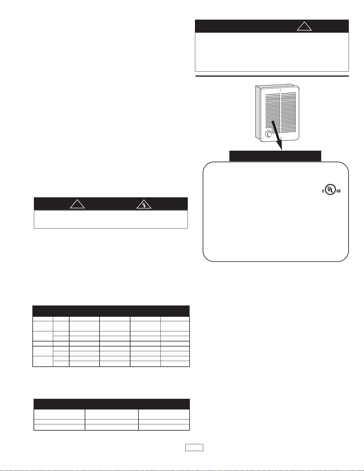
OPERATIONAL NOTICE
Your heater is equipped with an automatic reset limit control that will automatically turn the heater OFF to prevent overheating. Should this occur, the
red warning light will illuminate and will continue to shine until the limit
resets. Your heater is also equipped with a backup “one shot” thermal protection fuse that will permanently disable the unit, to prevent a fire, if the
reset limit fails. If the red warning light illuminates and the heater never
restarts, the “one shot” thermal protection fuse has been activated and you
should consult the factory.
CAUTION
a
CAUTION
THE ILLUMINATED INDICATOR LIGHT SIGNIFIES THE HEATER HAS BEEN
SUBJECTED TO SOME ABNORMAL CONDITION CAUSING IT TO OVERHEAT.
CHECK HEATER TO INSURE THAT IT HAS NOT BEEN BLOCKED IN ANY
MANNER (IF SO, REMOVE BLOCKAGE). IF THERE IS NO INDICATION OF
BLOCKAGE IT IS RECOMMENDED THE HEATER BE CHECKED BY A REPUTABLE ELECTRICIAN OR REPAIR SERVICE TO INSURE THE HEATER HAS
NOT BEEN DAMAGED. DO NOT CONTINUE TO USE HEATER IF LIGHT IS ON.
!
NAMEPLATE
MODEL NO.
FAN FORCED WALL HEATERS
CALEFACTOR DE PARED CON VENTILADOR
APPAREL MURAL À AIR PULSÉ POUR
240/208 2250/1688/1125/563
a
VOLTS AC 1688/1266/844/422
9.4/7.0/4.7/2.3 WATTS
8.1/6.1/4.1/2.0 60HZ1PH
AMPS
USE ONLY WITH CO2-BB BACK BOX.
DO NOT OPERATE WITHOUT GRILLE IN PLACE.
SÓLO DEBE USARSE CON LA CAJA POSTERIOR CO2-BB.
NO DEBE ENCENDERSE SIN LA REJILLA.
UTILISER SEULEMENT AVEC UN BOÎTERIER ARRIÉRE CO2-BB.
NE PAS UTILISER SE LA GRILLE N’EST PAS EN PLACE.
MARLEY ENGINEERED PRODUCTS
BENNETTSVILLE, SC 29512 USA 4104-2218-005
C2224IFB DATE CODE 0403
ROOM HEATER
EXAMPLE
774G LISTED
TYPE
CO2
TABLE 1
MODEL VOLTS WATTS/AMPS WATTS/AMPS WATTS/AMPS WATTS/AMPS
C1512IF
C1512T2
C1524T2
C2028IF 208 200W/9.6 1500W/7.2 1000W/4.8 500W/2.4
C2024IF 240 2000W/8.3 1500W/6.3 1000W/4.2 500W/2.1
C2024T2 208 1500W/7.2 1125W/5.4 750W/3.6 375W/1.8
C2224IF 240 2250W/9.4 1688W/7.0 1125W/4.7 563W/2.3
C2224T2 208 1688W/8.1 1266W/6.1 844W/4.1 422W/2.0
NOTE: “IF” Inner Frame models must be used with CBB (Type CO2-BB)
Back Box. “T2” Thermostat Models include integral thermostat.
NOTE: For installations over 7500 ft. above sea level we recommend to use
heaters with wattages under 1500 watts.
120 1500W/12.5 1125W/9.4 750W/6.3 375W/3.1
240 1500W/6.3 1125W/4.7 750W/3.1 375W/1.6
208 1125W/5.4 844W/4.1 563W/2.7 281W/1.4
TABLE 2
TOTAL AMPS
0 thru 12
12.1 thru 16
WIRE SIZE (COPPER)
#14
#12
CIRCUIT BREAKER
OR FUSE SIZE
15 Amps
20 Amps
3
Page 4
All products manufactured by Marley Engineered Products are warranted against defects in workmanship and materials for one year from date of installation, except heat-
LIMITED WARRANTY
ing elements which are warranted against defects in workmanship and materials for five years from date of installation. This warranty does not apply to damage from
accident, misuse, or alteration; nor where the connected voltage is more than 5% above the nameplate voltage; nor to equipment improperly installed or wired or maintained in violation of the product’s installation instructions. All claims for warranty work must be accompanied by proof of the date of installation.
The customer shall be responsible for all costs incurred in the removal or reinstallation of products, including labor costs, and shipping costs incurred to return products
to Marley Engineered Products Service Center. Within the limitations of this warranty, inoperative units should be returned to the nearest Marley authorized service center or the Marley Engineered Products Service Center, and we will repair or replace, at our option, at no charge to you with return freight paid by Marley. It is agreed that
such repair or replacement is the exclusive remedy available from Marley Engineered Products.
THE ABOVE WARRANTIES ARE IN LIEU OF ALL OTHER WARRANTIES EXPRESSED OR IMPLIED, AND ALL IMPLIED WARRANTIES OF MERCHANTABILITY
AND FITNESS FOR A PARTICULAR PURPOSE WHICH EXCEED THE AFORESAID EXPRESSED WARRANTIES ARE HEREBY DISCLAIMED AND EXCLUDED
FROM THIS AGREEMENT. MARLEY ENGINEERED PRODUCTS SHALL NOT BE LIABLE FOR CONSEQUENTIAL DAMAGES ARISING WITH RESPECT TO THE
PRODUCT, WHETHER BASED UPON NEGLIGENCE, TORT, STRICT LIABILITY, OR CONTRACT.
Some states do not allow the exclusion or limitation of incidental or consequential damages, so the above exclusion or limitation may not apply to you. This warranty
gives you specific legal rights, and you may also have other rights which vary from state to state.
For the address of your nearest authorized service center, contact Marley Engineered Products in Bennettsville, SC, at 1-800-642-4328. Merchandise returned to the factory must be accompanied by a return authorization and service identification tag, both available from Marley Engineered Products. When requesting return authorization, include all catalog numbers shown on the products.
HOW TO OBTAIN WARRANTY SERVICE AND
WARRANTY PARTS PLUS GENERAL INFORMATION
1. Warranty Service or Parts 1-800-642-4328
2. Purchase Replacement Parts 1-800-654-3545
3. General Product Information www.marleymep.com
Note: When obtaining service always have the following:
1. Model number of the product
2. Date of manufacture
3. Part number or description
Part No. 5200-2638-004
470 Beauty Spot Rd. East
Bennettsville, SC 29512 USA
ECR 39219
09/11
4
Page 5

CUBIERTA FRONTAL
CAJA
POSTERIOR
Serie C
Modelo B
Calefactores de pared con
ventilador, con placa Clip’n’Fit
Patente de los E. U. de A. No 6 172 343
®
CONJUNTO DE CALEFACTOR
Instrucciones de instalación y mantenimiento
Estimado propietario:
¡Felicitaciones! Gracias por comprar este nuevo calefactor fabricado por Marley Engineered Products. Al seleccionar el producto de más alta calidad de la industria de calefacción, usted ha hecho una sabia inversión. Por favor, lea cuidadosamente
las instrucciones de instalación y mantenimiento incluídas en este manual. Así podrá disfrutar de años de calefacción confortable y eficiente con este producto de Marley Engineered Products ... el líder de la industria en diseño, fabricación, calidad y servicio.
… Los empleados de Marley Engineered Products
ADVERTENCIA
Lea Cuidadosamente – Estas instrucciones están escritas para
ayudarle a superar las dificultades que podrían aparecer durante la instalación de calefactores. El estudio previo de estas instrucciones puede
ahorrarle considerable tiempo y dinero en el futuro. Observe los
procedimientos que siguen, y reducirá el tiempo de instalación a un
mínimo. ATENCION – PARA REDUCIR EL RIESGO DE INCENDIO Y
CHOQUE ELECTRICO:
1. Antes de proceder a tareas de conexionado o de reparación del calefactor,
desconecte toda la alimentación eléctrica que llega al mismo desde el
tablero principal de servicio.
2. Todo el conexionado debe hacerse de conformidad con los Códigos
Eléctricos nacionales y locales, y el calefactor debe estar conectado a tierra.
3. Antes de aplicar alimentación eléctrica, verifique que la tensión de alimentación provista al calefactor sea compatible con la tensión nominal
impresa en la placa de características del calefactor.
4. Cuando está en funcionamiento, el calefactor está muy caliente. Para evitar
quemaduras, no deje que su piel haga contacto directo con las superficies
calientes.
5. No inserte ni permita que entren objetos extraños en ninguna abertura de
ventilación o de descarga, porque esto puede ser causa de choque eléctrico,
incendio o daño al calefactor.
6. Cuando el calefactor está funcionando, la rejilla y la descarga de aire están
calientes. No instale ni use el calefactor en cualquier área en la que la circulación del aire desde el mismo pueda estar bloqueada u obstruída. No lo
instale detrás de puertas, muebles, toalleros, cortinas o cajas. El aire caliente
puede dañar algunas telas y plásticos. Conserve siempre los cordones eléctricos, ropas de cama, cajones, cortinados y otros materiales combustibles
alejados del calefactor. No instale el calentador en techo.
7. Un calefactor tiene en su interior piezas calientes, y piezas en donde se producen arcos o chispas. No lo use en áreas en las que se use o almacene
gasolina, pintura o líquidos inflamables.
8. Use este calefactor únicamente en la forma prevista en este manual.
Cualquier otra forma de uso no recomendada por el fabricante puede ser
causa de incendio, choque eléctrico o daños personales.
9. Este calefactor no está aprobado para su uso en atmósferas corrosivas tales
como áreas marítimas, invernaderos o lugares de almacenamiento de
productos químicos.
10. Cuando se lo monte en una pared, el calefactor debe instalarse únicamente
en posición vertical (con el motor debajo del elemento calefactor), como se
muestra en este manual. No lo instale sobre un costado, en forma invertida,
o en un cielorraso.
11. El calefactor debe instalarse con la Caja Posterior CBB (Tipo CO2-BB).
12. Deben mantenerse las distancias mínimas que se indican a continuación:
• Para montaje en pared:
• Montaje en el cielorraso (máx.: 1000 watts)
13. Al tender los cables, la alimentación eléctrica debe ingresar a través de prepunzonados ubicados en el lado izquierdo de la caja posterior. No use los prepunzonados del lado derecho de la caja posterior. Vea la Figura 1. Para determinar cuál es el lado izquierdo y cuál el derecho: 1.) Oriente la caja posterior
de manera que la marca ‘ARRIBA’ (‘TOP’) y las flechas estén visibles y en
posición vertical; y 2.) Asegúrese de que la plataforma del ventilador esté orientada con el lado del elemento calefactor sobre el lado ‘ARRIBA’ (‘TOP’) de
la caja posterior.
14. No haga funcionar el calefactor sin haber instalado la rejilla.
15. No use el calefactor para fines de secado. La pintura, el yeso, el aserrín y el
polvo proveniente del lijado de paredes secas provocarán daños al calefactor,
por lo que no deben entrar al mismo.
16. Conserve el calefactor limpio. Vea las instrucciones de mantenimiento y de
limpieza en la página 3.
!
Del calefactor al piso: 114 mm (4,5")
Del calefactor a la pared adyacente: 114 mm (4,5")
Del calefactor al cielorraso: 305 mm (12")
Entre el calefactor y cualquier pared: 305 mm (12")
GUARDE ESTAS INSTRUCCIONES
Page 6

Para montaje en pared únicamente
LAMP
R
M
ELEMENT
TCO
LIMIT
CONTROL
MOTOR
CLIP'N'FIT
®
2
1
3
RED
JUMPER
BLUE
JUMPER
REMOTE 1
PO LE T'S TAT
BLACK
RED
REMOTE OR
OPTIONAL 2
PO LE T'S TAT
BLACK
RED
L1
L2/N
GENERALIDADES
• Los calefactores serie C están diseñados para una instalación empotrada en un travesaño de 50 mm x 100 mm (2" x 4"), o sección de pared mayor, usando la caja posterior modelo CBB (Tipo CO2-BB). El calefactor puede cablearse usando cable estándar
para edificios (60
• La altura óptima de montaje para este calefactor es de 457 mm a 610 mm (18" a 24")
0
C como mínimo).
desde el piso hasta el fondo de la caja posterior. No lo instale en ningún caso a menos
de 114 mm (4,5") del piso o de la pared adyacente.
Montaje en el cielorraso
• Los calefactores serie C están diseñados para montaje en el cielorraso, siempre que
su potencia no supere 1000 watts. Para que su calefactor sea apto para una aplicación
en el cielorraso, se lo debe reajustar a 1000 watts o menos. (Vea más adelante
‘Cambio de la potencia’)
• El espacio libre óptimo en relación con la superficie de cualquier pared es 30,5 cm (12
pulgadas). No monte el calefactor en el cielorraso si no puede mantenerse esta distancia.
• Los calefactores de cielorraso pueden también instalarse con montaje empotrado o
superficial.
Los calefactores están aprobados también para montaje semiempotrado o en superficie, en paredes y cielorrasos. Consulte las instrucciones para instalación del bastidor CSM para Montaje
Superficial.
INSTALACION DE LA CAJA POSTERIOR
EN UNA CONSTRUCCION NUEVA
NOTA: Si la pared ha sido construída y su superficie terminada anteriormente, siga las
instrucciones para ‘INSTALACION DE LA CAJA POSTERIOR EN UNA CONSTRUCCION
EXISTENTE’.
DOBLE LA ALETA
HACIA AFUERA
ABRAZADERA
PARA CABLES
AGUJEROS
Figura 1
DE GUIA
CAJA
POSTERIOR
CLAVOS O
TORNILLOS
CABLE DEL
CIRCUITO
DE ALIMENTACION
1. Al instalar la caja posterior, tenga en cuenta el espesor de la superficie termina-
da. El borde de la caja posterior debe instalarse enrasado con la superficie terminada. En el costado de la caja posterior se han provisto marcas para paredes
terminadas de 13 mm (1/2") y de 16 mm (5/8").
2. Determine cuál de los lados de la caja posterior va a montarse contra un travesaño
o viga, y doble las aletas de los ángulos posteriores 90º hacia afuera, de man-
era que la caja quede escuadrada con el travesaño después de la instalación.
3. Quite uno de los prepunzonados del lado izquierdo de la caja posterior, e instale un
conector para cable o para conducto. (Vea la advertencia 13).
4. Posicione la caja posterior de lado contra el travesaño o viga del cielorraso, y
asegúrela mediante clavos o tornillos, como se muestra en la Figura 1.
NOTA: La caja posterior debe instalarse en un travesaño de la pared o viga del cielorraso,
y asegurarse mediante clavos o tornillos, como se muestra en la Figura 1.
5. Tienda el cable de alimentación eléctrica a través del conector, dejando alrededor
de 15 cm (6") de cable dentro de la caja.
6. Conecte el conductor de tierra del cable de alimentación eléctrica al conductor verde
de puesta a tierra provisto.
NOTA: En los lados de la caja posterior se han provisto agujeros de guía para tornillos para
chapa No 8. Después de haber terminado la pared o el cielorraso, inserte un tornillo para
chapa M4 (No 8) (longitud recomendada: 25 mm / 1") a través del lado de la caja que no
está montado en el travesaño. Esto impedirá que la caja salga hacia afuera cuando se
instale el conjunto del calefactor. (Vea la Figura 1).
INSTALACION DE LA CAJA POSTERIOR
EN UNA CONSTRUCCION EXISTENTE
1. El borde de la caja posterior debe instalarse enrasado con la superficie terminada.
Determine cuál de los lados de la caja posterior va a montarse contra un travesaño
o viga, y doble las aletas de los ángulos posteriores 90º hacia afuera, de manera
que la caja quede escuadrada con el travesaño después de la instalación.
(Vea la Figura 1).
2. Corte con cuidado un agujero de 239 mm (9-3/8") de ancho por 284 mm (11-1/8") de
longitud. Uno de los bordes del agujero debe cortarse a lo largo del borde del
travesaño de la pared.
3. Haga llegar el cable de alimentación eléctrica al lugar de montaje del calefactor,
dejando al menos 255 mm (10") de cable para el conexionado.
4. Quite el prepunzonado deseado del lado izquierdo de la caja posterior.
5. Instale la abrazadera para cable e instale el cable en la caja, dejando al menos 152
mm (6") de cable en la caja para el conexionado.
6. Conecte el conductor de tierra del cable de alimentación eléctrica al conductor verde
de puesta a tierra provisto.
7. Acomode la caja posterior en el agujero de montaje de la pared, insertando primero el
extremo de la caja que tiene el cable, y haciendo girar luego la caja hasta su posición.
8. Asegure la caja al travesaño de la pared o viga del cielorraso, por medio de clavos o
tornillos.
a
ATENCION
PARA PREVENIR EXCESO DE ALAMBRE DE LA FUENTE DEL CABLEADO DEL CORTE
POSIBLE DEL DAÑOS DENTRO DE BACKBOX PARA PROPORCIONAR APROXIMADAMENTE 6 PULGADAS PARA LA CONEXIÓN A LOS PLOMOS DEL CALENTADOR. DESPUÉS
DE QUE LAS CONEXIONES SEAN APRETADAS SEAN APRETADAS Y TODO EL CABLEADO
SE COLOCA LEJOS DE LA ASPA DEL VENTILADOR Y DEL ELEMENTO DE CALEFACCIÓN.
!
NOTA: En los lados de la caja posterior se han provisto agujeros de guía para tornillos para
chapa No 8. Después de haber terminado la pared o el cielorraso, inserte un tornillo para
chapa M4 (No 8) (longitud recomendada: 25 mm / 1") a través del lado de la caja que no
está montado en el travesaño o viga. Esto impedirá que la caja salga hacia afuera cuando
se instale el conjunto del calefactor. (Vea la Figura 1).
NOTA: Los calefactores están cableados en fábrica de acuerdo con la tensión y la potencia
indicadas en su placa de características. Vea los detalles en la Tabla 1 de la página 3. Si
desea una potencia menor, vea la sección ‘PARA CAMBIAR LA SALIDA DE POTENCIA’, y
realice el cambio antes de instalar el calefactor.
LAMPARA
PHASE
ROJO
NEUTRE
NEGRO
TERMOSTATO DE 2
POLOS, REMOTO U
OPTATIVO
ROUGE
TERMOSTATO DE
1 POLO, REMOTO
NEGRO
PUENTE DE PUENTE DE
CABLE, ROJO CABLE, AZUL
CLIP 'N' FIT
CONTROL
DE LIMITE
MOTOR
®
PROTECCION
TERMICA
ELEMENTO
CALEFACTOR
Figura 2 Diagrama de conexionado
INSTALACION Y CONEXIONADO DEL
CONJUNTO CALEFACTOR / VENTILADOR
1. Siguiendo el diagrama de conexionado (Figura 2), conecte los conductores de ali-
mentación a los cables de conexión del calefactor situados en la caja posterior, por
medio de conectores de cable adecuados.
NOTA: Para calefactores de 120 Volt, conecte el conductor de alimentación eléctrica blanco (neutro)
al conductor flexible blanco, o rojo con indicador tipo bandera blanco, del calefactor, y conecte el
conductor de alimentación eléctrica negro al conductor flexible negro del calefactor.
2. Asegure el conductor de tierra de la alimentación eléctrica bajo el tornillo verde de
puesta a tierra de la caja posterior (o el conductor verde de puesta a tierra, si existe).
3. Acomode el conjunto calefactor / ventilador en la caja posterior, y sujételo en su posi-
ción con los dos (2) tornillos provistos, a través de las ranuras centrales de los lados
del conjunto del ventilador.
POTENCIA (Watt)
C1512IF C2024IF C2224IF Puente 1 Puente 2
C1512T2 C1524T2 C2028IF C2024T2 C2224T2 (Puente de (Puente de
@120V @208V @240V @208V @208V @240V @208V @240V cable, azul) cable, rojo)
1500 1125 1500 2000 1500 2000 1688 2250 Dejar Dejar
1125 844 1125 1500 1125 1500 1266 1688 Cortar Dejar
750 563 750 1000 750 1000 844 1125 Dejar Cortar
375 281 375 500 375 500 422 563 Cortar Corta
PUENTE DE PUENTE DE
CABLE, AZUL CABLE, ROJO
Figura 3 Placa Clip’n’Fit
PARA CAMBIAR LA SALIDA DE POTENCIA
El cuadro que sigue a continuación muestra las potencias disponibles para cada modelo.
Cada calefactor está cableado en fábrica para su potencia máxima. Las últimas dos columnas del cuadro se refieren a los puentes de cable de la placa CLIP’n’FIT®. Para cambiar la
potencia corte el puente 1 y/o el puente 2, como se muestra en el cuadro. Elimine los puentes
por completo cortándolos en ambos extremos, tan cerca de la placa como sea posible.
6
®
r
Page 7

INSTALACION DE LA CUBIERTA (REJILLA)
FRONTAL Y LA PERILLA DEL TERMOSTATO
1. Sujete la cubierta frontal al conjunto del calefactor por medio de los dos (2) tornillos
largos suministrados.
2. Coloque la perilla del termostato sobre el eje del termostato (si lo hubiera), y presiónela hasta su posición.
VERIFICACION Y OPERACION DEL CALEFACTOR
1. Después de que el calefactor esté montado por completo, haga girar la perilla del
(Si se ha provisto un termostato interno)
termostato en sentido antihorario hasta que el control llegue a un tope. Esta es la
posición de calor mínimo.
2. Conecte la alimentación eléctrica al calefactor en el tablero de distribución principal.
3. En esas condiciones, el calefactor no debe funcionar. Si funciona, desconecte la
alimentación eléctrica y vuelva a inspeccionar el conexionado.
4. Haga girar la perilla del termostato en sentido horario hasta que llegue a un tope
(posición de calor máximo).
5. El calefactor y el ventilador deben encenderse. Si el calefactor y el ventilador no
entran en funcionamiento, desconecte la alimentación eléctrica e inspeccione el
conexionado.
6. Deje que el calefactor continúe funcionando hasta que la temperatura ambiente
alcance el nivel de confort deseado. Luego haga girar la perilla del termostato
lentamente en sentido antihorario, hasta que se escuche el ‘clic’ que indica que el
termostato apagó el calefactor.
7. Puede que sea necesario volver a ajustar el termostato una o más veces hasta
que se alcance el nivel de confort exacto. La rotación en sentido horario aumentará el tiempo durante el cual el calefactor producirá calor. La rotación en sentido
antihorario reducirá el tiempo durante el cual el calefactor está encendido.
NOTA: Para obtener los mejores resultados, el calefactor debe permanecer constantemente ENCENDIDO (‘ON’) durante la temporada en que se necesite calefacción, ya que el
termostato, siempre que esté correctamente ajustado, mantendrá la temperatura deseada.
En la posición extrema en sentido antihorario, el calefactor permanecerá APAGADO (‘OFF’)
hasta que la temperatura de la habitación disminuya bien por debajo del punto de congelación.
MANTENIMIENTO
ATENCION
!
PARA REDUCIR EL RIESGO DE INCENDIO Y DE CHOQUE ELECTRICO, DESCONECTE
TODA LA ALIMENTACION ELECTRICA QUE LLEGA AL CALEFACTOR EN EL TABLERO PRINCIPAL DE SERVICIO ANTES DE PRESTAR SERVICIO O DE REALIZAR EL MANTENIMIENTO.
PARA LIMPIAR EL CALEFACTOR: Para obtener el máximo rendimiento, el calefactor
debe limpiarse anualmente. Antes de la limpieza, asegúrese de que la alimentación
eléctrica esté desconectada y el calefactor esté frío. En primer lugar retire la perilla
tirando de ella directamente hacia afuera, luego retire la rejilla frontal y limpie la rueda
del soplador mediante una aspiradora con accesorio de cepillo. Si se desea, puede
limpiarse la rejilla con un trapo ligeramente húmedo.
AVISO OPERATIVO
Su calefactor está equipado con un control de límite de temperatura con reposición
automática, que apagará automáticamente el calefactor para prevenir el sobrecalentamiento. Si esto ocurriera, la luz roja de advertencia se encenderá, y continuará
encendida hasta que el límite vuelva a su estado anterior. Su calefactor está equipado
también con un fusible de protección térmica de respaldo del tipo de ‘disparo único’, que
en caso de falla del límite de temperatura desactivará la unidad en forma permanente a
fin de prevenir un incendio. Si la luz roja de advertencia está encendida y el calefactor
nunca vuelve a arrancar, significa que la protección térmica de ‘disparo único’ ha sido
activada y que debe consultar a la fábrica.
TABLA 1
MODELO (VOLT) CORRIENTE (A) CORRIENTE (A) CORRIENTE (A) CORRIENTE (A)
C1512IF
C1512T2
C1524T2
C2028IF 208 200W/9,6 1500W/7,2 1000W/4,8 500W/2,4
C2024IF 240 2000W/8,3 1500W/6,3 1000W/4,2 500W/2,1
C2024T2 208 1500W/7,2 1125W/5,4 750W/3,6 375W/1,8
C2224IF 240 2250W/9,4 1688W/7,0 1125W/4,7 563W/2,3
C2224T2 208 1688W/8,1 1266W/6,1 844W/4,1 422W/2,0
NOTA: Los modelos ‘IF’ de bastidor interior deben usarse con la Caja Posterior CBB
(Tipo CO2-BB). Los modelos ‘T2’ incluyen un termostato incorporado.
NOTA: Para instalaciones situadas a más de 2300 m (7500 pies) por sobre el nivel del
mar, recomendamos usar calefactores con potencias menores que 1500 watt.
TENSION POTENCIA (WATT)/ POTENCIA (WATT)/ POTENCIA (WATT)/ POTENCIA (WATT)/
120 1500W/12,5 1125W/9,4 750W/6,3 375W/3,1
240 1500W/6,3 1125W/4,7 750W/3,1 375W/1,6
208 1125W/5,4 844W/4,1 563W/2,7 281W/1,4
a
ATENCION
LA LUZ INDICADORA ENCENDIDA SIGNIFICA QUE EL CALEFACTOR HA ESTADO
SOMETIDO A ALGUNA CONDICION ANORMAL QUE CAUSO SU SOBRECALENTAMIENTO.
REVISE EL CALEFACTOR PARA ASEGURARSE DE QUE NO HAYA SIDO BLOQUEADO DE
ALGUNA MANERA (SI FUERA ASI, ELIMINE EL BLOQUEO). SI NO HUBIERA INDICACION
DE BLOQUEO, SE RECOMIENDA HACER REVISAR EL CALEFACTOR POR UN ELECTRICISTA O SERVICIO DE REPARACION RECONOCIDO, PARA ASEGURARSE DE QUE
EL CALEFACTOR NO HAYA SUFRIDO ALGUN DAÑO. SI LA LUZ PERMANECE ENCENDIDA, NO CONTINUE USANDO EL CALEFACTOR.
!
PLACA DE CARACTERISTICAS
MODEL NO.
FAN FORCED WALL HEATERS
CALEFACTOR DE PARED CON VENTILADOR
APPAREL MURAL À AIR PULSÉ POUR
240/208 2250/1688/1125/563
a
VOLTS AC 1688/1266/844/422
9.4/7.0/4.7/2.3 WATTS
8.1/6.1/4.1/2.0 60HZ1PH
AMPS
USE ONLY WITH CO2-BB BACK BOX.
DO NOT OPERATE WITHOUT GRILLE IN PLACE.
SÓLO DEBE USARSE CON LA CAJA POSTERIOR CO2-BB.
NO DEBE ENCENDERSE SIN LA REJILLA.
UTILISER SEULEMENT AVEC UN BOÎTERIER ARRIÉRE CO2-BB.
NE PAS UTILISER SE LA GRILLE N’EST PAS EN PLACE.
MARLEY ENGINEERED PRODUCTS
BENNETTSVILLE, SC 29512 USA 4104-2218-005
C2224IFB DATE CODE 0403
ROOM HEATER
EJEMPLO
774G LISTED
TYPE
CO2
CORRIENTE TOTAL (A)
0 a 12
12,1 a 16
TABLA 2
CALIBRE DEL
CONDUCTOR (COBRE)
No 14
No 12
TAMAÑO DEL INTERRUPTOR
AUTOMATICO O FUSIBLE
15 A
20 A
7
Page 8

Todos los productos fabricados por Marley Engineered Products están garantizados contra defectos de fabricación y de materiales por un año desde la fecha de instalación, a excepción de los ele-
GARANTIA LIMITADA
mentos calefactores, que están garantizados contra defectos de fabricación y de materiales por cinco años desde la fecha de instalación Esta garantía no se aplica a daños debidos a accidente,
mal uso o alteración, ni a los casos en que la tensión eléctrica conectada supere a la tensión nominal -indicada en la placa de características- en más de un 5 %, ni a equipos que hayan sido instalados o cableados incorrectamente, o mantenidos en forma violatoria de lo indicado en las instrucciones de instalación del producto. Todo reclamo por trabajos en garantía debe acompañarse con
una prueba de la fecha de instalación.
El cliente será responsable de todos los costos incurridos en el retiro o reinstalación de productos, incluyendo los costos de mano de obra y los costos de envío incurridos para regresar productos
a un Centro de Servicio de Marley Engineered Products. Dentro de las limitaciones de esta garantía, las unidades que no funcionan deben regresarse al centro de servicio autorizado Marley más
cercano, o al Centro de Servicio de Marley Engineered Products, y nosotros lo repararemos o reemplazaremos, a nuestra opción, sin cargo para usted, con el flete de retorno pagado por Marley.
Se acuerda que tal reparación o reemplazo es el único recurso que Marley Engineered Products pone a su disposición.
LAS GARANTIAS EXPUESTAS MAS ARRIBA TOMAN EL LUGAR DE TODA OTRA GARANTIA, EXPRESA O IMPLICITA, Y POR LA PRESENTE SE DECLINA Y EXCLUYE DE ESTE ACUERDO TODA GARANTIA IMPLICITA DE COMERCIABILIDAD Y ADECUACION A UN PROPOSITO PARTICULAR QUE EXCEDA LAS GARANTIAS EXPRESAS ANTEDICHAS. MARLEY ENGINEERED PRODUCTS NO SE HARA RESPONSABLE POR DAÑOS CONSIGUIENTES QUE SE PRODUZCAN CON RESPECTO AL PRODUCTO, EN BASE YA SEA A NEGLIGENCIA,
AGRAVIO, RESPONSABILIDAD ESTRICTA, O CONTRATO.
Algunos estados o jurisdicciones no permiten la exclusión o limitación de daños incidentales o consiguientes, de modo que la exclusión o limitación expresada más arriba puede no aplicarse a su
caso. Esta garantía le da derechos legales específicos, y usted puede tener también otros derechos, que varían de un estado o jurisdicción a otro.
Para obtener la dirección de su centro de servicio autorizado más cercano, comuníquese con Marley Engineered Products, en Bennettsville, SC, Estados Unidos de América, llamando al 1-800642-4328. Toda mercadería regresada a la fábrica debe ser acompañada por una autorización de retorno y una etiqueta de identificación de servicio, disponibles ambas en Marley Engineered
Products. Cuando solicite la autorización de retorno, incluya todos los números de catálogo mostrados en los productos.
COMO OBTENER SERVICIO EN GARANTIA,
PIEZAS DE REPUESTO E INFORMACION GENERAL
1. Servicio o repuestos, en garantía: 1-800-642-4328
2. Compra de piezas de repuesto: 1-800-654-3545
3. Información general sobre productos: www.marleymep.com
Nota: Cuando solicite servicio, siempre dé la información que sigue:
1. Número de modelo del producto
2. Fecha de fabricación
3. Número de parte o descripción
N° document 5200-2638-004
470 Beauty Spot Rd. East
Bennettsville, SC 29512 USA
ECR 39219
09/11
8
Page 9

CAISSON ARRIÈRE
Série C
modèle B
Pulso-radiateurs muraux
avec tableau Clip’n’Fit
Brevet américain No 6,172,343
®
Instructions d'installation et d'entretien
Cher client,
ENSEMBLE DE
RADIATEUR
FACE AVANT
Félicitations ! Merci d'avoir acheté ce nouveau radiateur fabriqué par une division de Marley Engineered Products. Vous
avez fait un sage investissement en sélectionnant un produit de la plus haute qualité dans l'industrie du chauffage. Veuillez
lire avec soin les recommandations d'installation et d'entretien données dans ce manuel. Vous devriez bénéficier d'années de
confort de chauffage efficace avec ce produit de Marley Engineered Products … le numéro un de cette industrie en conception, fabrication, qualité et service.
… les employés de Marley Engineered Products
AVERTISSEMENT
À lire attentivement – Ces instructions sont écrites pour vous
aider à éviter des difficultés qui pourraient survenir durant l'installation
des radiateurs. En les étudiant d'abord vous pouvez économiser ensuite
pas mal de temps et d'argent. Observez les procédures qui suivent et
réduisez votre temps d'installation à un minimum. ATTENTION - POUR
RÉDUIRE LE RISQUE D’INCENDIE OU DE COMMOTION
ÉLECTRIQUE :
1. Débrancher toute alimentation allant vers le radiateur au niveau du tableau de
distribution principal avant de câbler ou d'entretenir.
2. Tout câblage doit être en conformité avec les réglementations électriques
nationales et locales, et le radiateur doit être relié à la terre en précaution contre une possible électrocution.
3. Vérifier que le secteur d'alimentation arrivant au radiateur correspond bien aux
spécifications imprimées sur sa plaque signalétique avant de le mettre sous
tension.
4. Ce chauffage est brûlant quand il fonctionne. pour éviter des brûlures ne pas
mettre la peau nue en contact avec ses surfaces.
5. Ne pas insérer ou laisser entre des objets étrangers dans n'importe quelle
ouverture de ventilation ou évacuation, car cela pourrait causer une commotion électrique, un incendie, ou endommager le radiateur.
6. La grille et l’air évacué sont chauds pendant le fonctionnement. Ne pas
installer ou utiliser le radiateur dans une zone où le courant d’air du radiateur
pourrait être bloqué ou obstrué. Ne l’installez pas derrière portes, meubles,
porte-serviettes, rideaux ou boîtier. L’air chaud peut endommager certains tissus ou plastiques. Garder toujours les cordons électriques, literies, caisses,
tentures, et autres matières combustibles loin du radiateur. N'installez pas le
réchauffeur dans le plafond
7. Un radiateur comporte à l'intérieur des parties chaudes et
CONSERVER CES INSTRUCTIONS
pouvant provoquer un arc électrique (étincelles). Ne pas l'utiliser dans des
zones où sont entreposés essence, peinture ou liquides inflammables.
8. N’utiliser ce radiateur que comme indiqué dans ce manuel. Tout autre
utilisationnon recommandée par le constructeur peut provoquer incendie,
commotion électrique et dommages corporels.
9. Ce radiateur n'est pas approuvé pour utilisation en atmosphères corrosives,
comme air salin, serres ou zones de stockage de produits chimiques.
10. Quand il est monté au mur, le radiateur ne doit être placé qu’en position verti-
cale (moteur sous l’élément chauffant) comme montré dans ce manuel. Ne
pas le monter de côté ou à l’envers, ou bien au plafond.
11. Le radiateur doit être installé avec le caisson arrière CBB (Type CO2-BB).
12. Les espacements minimum suivants doivent être respectés en montage
mural.
• Montage au plafond (Max. 100 W)
13. Pour le câblage, l’alimentation électrique doit entrer par les pastilles à enfon-
cer à gauche du coffret arrière. Ne pas utiliser les trous à enfoncer du côté
droit du coffret. Se reporter au Schéma 1. Pour déterminer quel est la côté
gauche ou droite : 1) Orienter le caisson arrière de façon à ce que le marquage « TOP » est les flèches soient visibles et vers le haut. 2) Vérifier que la
plate-forme de ventilateur est orientée avec le côté de l’élément vers le côté «
TOP » du caisson arrière.
14. Ne pas faire fonctionner le radiateur sans que sa grille soit installée.
15. Ne pas utiliser le radiateur pour de l’assèchement. Peinture, plâtre, sciure et
poussière de ponçage de cloisons pourraient endommager le radiateur qui ne
doit pas y être exposé.
16. Garder le radiateur propre. Se reportez aux instructions d’entretien en page 3.
!
Radiateur à plancher - 114 mm (4,5")
Radiateur au mur voisin - 114 mm (4,5")
Radiateur au plafond - 305 mm (12")
Appareil de chauffage sur mur (305 mm)
Page 10

Montage mural uniquement
LAMP
R
M
ELEMENT
TCO
LIMIT
CONTROL
MOTOR
CLIP'N'FIT
®
2
1
3
RED
JUMPER
BLUE
JUMPER
REMOTE 1
POL E T'STAT
BLACK
RED
REMOTE OR
OPTIONAL 2
PO LE T'S TAT
BLACK
RED
L1
L2/N
GÉNÉRALITÉS
• Les radiateurs Série C sont conçus pour une installation encastrée entre des poteaux
muraux 2x4 ou plus, en utilisant le caisson arrière modèle CBB (Type CO2-BB). Le
radiateur peut être câblé en utilisant le fil standard pour le bâtiment (supportant au minimum 60°C).
• La hauteur de montage optimale pour le radiateur est 457 à 610 mm (18-24") du sol au
bas de caisson. En aucun cas il ne faut le monter à moins de 114 mm (4,5") du sol ou
d’un mur adjacent.
Montage au plafond
• Les radiateurs de Série C sont conçus pour pouvoir être montés au plafond si leur puis-
sance ne dépasse pas 1 000 watts. Pour que votre radiateur soit amené à la compatibilité avec une installation au plafond, il faut réduire sa puissance à 1 000 W ou moins
(voir plus loin Changement de puissance de sortie).
• Les espacements optimum par rapport à toute surface de cloison sont de 30 cm (12").
Ne montez pas le chauffage si ces espacements ne sont pas respectés.
• Les radiateurs au plafond peuvent être aussi montés encastrés ou affleurants.
Les radiateurs sont également approuvés pour un montage à demi encastré ou en surface, sur
murs ou plafonds. Reportez-vous aux instructions pour les installations du cadre CSM pour montage en surface.
INSTALLATION DU CAISSON ARRIÈRE
DANS UNE CONSTRUCTION NEUVE
REMARQUE : Si la finition de surface des murs est déjà mise en place, suivez les instruc-
tions plus loin de « INSTALLATION DU CAISSON ARRIÈRE DANS UNE CONSTRUCTION TERMINÉE ».
1. Prévoyez l’épaisseur de la finition de surface quand vous installez le caisson
arrière. Ses bords doivent être installés au même niveau que la surface de finition future. Il y a des repérages sur les côtés du caisson pour des épaisseurs de
finitions de 12,7 et 15,9 mm (1/2 et 5/8").
ONGLET
Schéma 1
SERRE-CÂBLE
AVANT-
TROUS
CAISSON
ARRIÈRE
PLIÉ
CLOUS
OU VIS
CÂBLE
D’ALIMENTATION
2. Déterminez quel côté du caisson arrière sera placé contre un poteau ou une solive
et pliez les onglets des angles arrière en les sortant à 90° pour que le caisson
arrière soit d’équerre avec le poteau après l’installation.
3. Enlevez l’un des trous à enfoncer du côté gauche du caisson arrière et installez un
raccordement de câble ou de conduite (voir l’avertissement 13).
4. Positionnez le caisson arrière contre le poteau mural ou la solive de plafond et fixez-
le en utilisant des clous ou des vis comme indiqué au Schéma 1.
REMARQUE : Le caisson arrière doit être installé sur un poteau mural ou une solive de
plafond et maintenu en utilisant des vis ou des clous comme indiqué au Schéma 1.
5. Passez le câble d’alimentation au travers du raccordement, en laissant environ 15
cm (6") de câble dans le caisson.
6. Branchez le fil de terre du câble d’alimentation avec la vis verte de terre fournie.
REMARQUE : Des avant-trous pour vis à tôle calibre 8 ont été prévus sur les côtés du cais-
son arrière. Une fois que le revêtement de mur ou de plafond a été mis en place, enfoncez
une vis à tôle calibre 8 de longueur recommandée de 25 mm (1") au travers du côté du
caisson qui n’est pas contre le poteau ou la solive. Cela empêchera le caisson de se
désengager quand vous monterez l’ensemble de radiateur dedans (voir le Schéma 1).
INSTALLATION DU CAISSON ARRIÈRE
DANS UNE CONSTRUCTION TERMINÉE
1. Les bords du caisson arrière doivent être installés au même niveau que la surface de fini-
tion actuelle. Déterminez quel côté du caisson arrière sera placé contre un poteau ou une
solive et pliez les onglets des angles arrière en les sortant à 90° pour que le cais-
son arrière soit d’équerre avec le poteau après l’installation (voir le Schéma 1).
2. Découpez avec précautions une ouverture rectangulaire de 239 mm (9-3/8") de large
sur 284 mm (11-1/8"). Un des bords de l'ouverture doit être contre un poteau mural ou
une solive de plafond.
3. Tirez un câble d’alimentation jusqu’à l’emplacement de montage du radiateur en
laissant au moins 255 cm (10") de câble sorti pour le raccordement.
4. Enlevez l’un des trous à enfoncer du côté gauche du caisson arrière.
5. Enfilez un passe-fil sur le câble et placez-le sur le trou du caisson arrière, en laissant
au moins 152 mm (6") de câble dans le caisson pour le raccordement.
6. Branchez le fil de terre du câble d’alimentation avec la vis verte de terre fournie.
7. Faites entrer le caisson arrière dans l’ouverture, en insérant d’abord le côté du caisson
d’entrée du câble d’alimentation puis en faisant pivoter le caisson en place.
8. Fixez le caisson contre le poteau ou la solive en utilisant des clous ou des vis.
REMARQUE : Des avant-trous pour vis à tôle calibre 8 ont été prévus sur les côtés du
caisson arrière. Enfoncez une vis à tôle calibre 8 de longueur recommandée de 25 mm (1")
au travers du côté du caisson qui n’est pas contre le poteau ou la solive. Cela empêchera
le caisson de se désengager quand vous monterez l’ensemble de radiateur dedans (voir
le Schéma 1).
a
ATTENTION
POUR EMPÊCHER LE FIL EXCESSIF D'APPROVISIONNEMENT DE CÂBLAGE DE COUPE
POSSIBLE DE DOMMAGES À L'INTÉRIEUR DE BACKBOX POUR FOURNIR APPROXIMATIVEMENT 6 POUCES POUR LE RACCORDEMENT AUX FILS DE RÉCHAUFFEUR. APRÈS
QUE LES RACCORDEMENTS SOIENT SERRÉS SOIENT SERRÉS ET TOUT LE CÂBLAGE
EST PLACÉ LOIN DE LA PALE DE VENTILATEUR ET DE L'ÉLÉMENT DE CHAUFFE.
!
REMARQUE : Les radiateurs ont leur câblage interne configuré à l'usine en conformité avec
leur plaque signalétique donnant modèle, tension et puissance. Reportez-vous au
tableau 1 en page 3 pour les détails. Voyez la section POUR MODIFIER LA PUISSANCE DE SORTIE si vous désirez une puissance plus faible et voulez le configurer
avant l’installation.
INSTALLATION ET CBLAGE DE
L’ENSEMBLE RADIATEUR/VENTILATEUR
1. En suivant les indications de raccordement du Schéma 2, branchez les fils de l’alimen-
tation secteur avec les fils du radiateur dans le caisson arrière, en utilisant des rac-
cords pour fils adéquats.
REMARQUE : Dans le cas des radiateurs en 12O volts,reliez le fil blanc de neutre de l’alimentation
avec le fil blanc (ou rouge marqué de blanc en torsade) du radiateur, et reliez le fil noir de phase de l’alimentation avec le fil noir du radiateur.
AMPOULE
PHASE
ROUGE
NEUTRE
NOIR
THERMOSTAT
BIPOLAIRE OPTION-
NEL OU DISTANT
ROUGE
THERMOSTAT
MONOPOLAIRE
DISTANT
NOIR
CAVALIER CAVALIER
ROUGE BLEU
CLIP 'N' FIT
CONTRÔLE
DE LIMITES
MOTEUR
®
TCO
ÉLÉMENT
Schéma 2 Diagramme de câblage
2. Fixez le fil de terre de l’alimentation sous la vis de terre verte dans le caisson arrière (ou
sur le fil vert de terre s’il est disponible).
3. Installez l’ensemble radiateur/ventilateur dans le caisson arrière et fixez-le en place avec
les deux (2) vis fournies au travers des fentes centrales de l’ensemble de ventilateur.
POUR MODIFIER LA PUISSANCE DE SORTIE
Le tableau ci-dessous donne les puissances en watts possibles par modèles. Chacun des radiateurs est câblé en avance à l’usine pour sa puissance maximale. Les deux dernière colonnes
se rapportent au tableau CLIP’n’FIT
er les cavaliers comme indiqué dans la table. Enlevez définitivement les cavaliers en les
®
. Pour modifier la puissance, il suffit d’enlever ou de laiss-
coupant aux deux extrémités aussi près du tableau que possible.
PUISSANCE EN WATTS
C1512IF C2024IF C2224IF
C1512T2 C1524T2 C2028IF C2024T2 C2224T2 Cavalier 1 Cavalier 2
En120V En208VEn240V En208V En208V En 240V En208V En240V bleu rouge
1500 1125 1500 2000 1500 2000 1688 2250 Laisser Laisser
1125 844 1125 1500 1125 1500 1266 1688 Couper Laisser
750 563 750 1000 750 1000 844 1125 Laisser Couper
375 281 375 500 375 500 422 563 Couper Couper
CAVALIER CAVALIER
BLEU ROUGE
Schéma 3 Tableau Clip’n’Fit
10
®
Page 11

INSTALLATION DU COUVERCLE AVANT (GRILLE)
ET DU BOUTON DE THERMOSTAT
1. Fixez le couvercle avant sur l’ensemble de radiateur en utilisant les deux (2) vis
longues fournies.
2. Placez le bouton de thermostat sur l‘axe de réglage du thermostat (si un thermostat interne est fourni) et enfoncez-le en position.
VÉRIFICATION ET UTILISATION DU RADIATEUR
1. Après l’installation complète du radiateur, faites tourner le bouton du radiateur
dans le sens inverse du sens des aiguilles d'une montre jusqu’au butoir d’arrêt.
Cela correspond au réglage de température minimum.
2. Mettez le radiateur sous tension par le commutateur principal du panneau.
3. Le radiateur ne devrait pas s'activer. S'il le faisait coupez son alimentation et
vérifiez le câblage.
4. Faites tourner le bouton du thermostat dans le sens des aiguilles d’une montre
jusqu’à sa butée d’arrêt (réglage de température maximum).
5. Le chauffage et le ventilateur doivent entrer en action. Si le radiateur et le ventilateur n’ont pas démarré, coupez l’alimentation et vérifiez le câblage.
6. Laissez le radiateur fonctionner jusqu’à ce que la température de la pièce
atteigne la température confortable souhaitée. Tournez alors le bouton du thermostat doucement dans le sens inverse des aiguilles d’une montre jusqu’à ce que le
thermostat coupe le contact.
7. Il peut être nécessaire de régler à nouveau le thermostat de temps en temps
jusqu’à ce que l’équilibre de température moyenne voulue soit atteint. La rotation
dans le sens des aiguilles d’une montre va augmenter la durée de génération de
chaleur du radiateur, Et dans le sens inverse pas réduire sa durée de chauffe.
REMARQUE : Pour les meilleurs résultats, le radiateur doit rester en marche (ON) en
permanence durant la saison de chauffage, du fait que le thermostat s’il est bien
réglé va maintenir le bonne température. Dans la position de bouton de thermostat tourné à fond dans le sens contraire des aiguilles d’une montre, le radiateur
va rester inactif jusqu’à ce que la température ambiante descende au dessous du
niveau de gel.
(dans le cas où un thermostat interne est fourni)
ENTRETIEN
ATTENTION
!
POUR RÉDUIRE LES RISQUES D’INCENDIE OU D’ÉLECTROCUTION, DÉBRANCHEZ
COMPLÈTEMENT L’ALIMENTATION ÉLECTRIQUE DU RADIATEUR EN AMONT AVANT DE
LE DÉPANNER OU D’INTERVENIR DESSUS.
NETTOYAGE DU RADIATEUR : Le radiateur doit être nettoyé annuellement pour
préserver toute son efficacité. Avant de le nettoyer vérifiez que son alimentation est
coupée et qu’il a refroidi. Enlevez d’abord le bouton de thermostat en le tirant dans l’axe,
puis démontez la grille de façade et nettoyez la roue de ventilateur en utilisant un ventilateur avec un suceur à brosse. La grille peut être nettoyée avec un chiffon légèrement
humide si nécessaire.
CONSEIL D’UTILISATION
Votre radiateur est équipé d’un contrôle automatique de restauration sur limite qui va
automatiquement le couper pour éviter sa surchauffe. Si cela se produisait le voyant
rouge d’avertissement s’allumerait et resterait allumé temps que la limite resterait
dépassée. Votre radiateur est également équipé avec un fusible de dernier recours consommable pour une protection thermique évitant l’incendie, au cas ou la coupure précédente sur limite n’aurait pas fonctionné. Si le voyant rouge reste allumé sans que le radiateur ne s’active à nouveau, c’est que ce fusible de dernier secours s’est grillé et vous
devez consulter l’usine.
TABLEAU 1
MODÈLE VOLTS WATTS / AMPÈRES WATTS / AMPÈRES WATTS / AMPÈRES WATTS / AMPÈRES
C1512IF
C1512T2
C1524T2
C2028IF 208 200W/9,6 1500W/7,2 1000W/4,8 500W/2,4
C2024IF 240 2000W/8,3 1500W/6,3 1000W/4,2 500W/2,1
C2024T2 208 1500W/7,2 1125W/5,4 750W/3,6 375W/1,8
C2224IF 240 2250W/9,4 1688W/7,0 1125W/4,7 563W/2,3
C2224T2 208 1688W/8,1 1266W/6,1 844W/4,1 422W/2,0
120 1500W/12,5 1125W/9,4 750W/6,3 375W/3,1
240 1500W/6,3 1125W/4,7 750W/3,1 375W/1,6
208 1125W/5,4 844W/4,1 563W/2,7 281W/1,4
a
ATTENTION
LE VOYANT INDICATEUR ALLUMÉ SIGNALE QUE LE RADIATEUR A ÉTÉ SOUMIS À DES
CONDITIONS ANORMALES QUI L’ONT MIS EN SURCHAUFFE. VÉRIFIEZ-LE POUR VOUS
ASSURER QUE SON VENTILATEUR N’A PAS ÉTÉ BLOQUÉ D’UNE FAÇON OU D’UNE
AUTRE (S’IL Y A LIEU DÉBLOQUEZ-LE). S’IL N’Y A PAS D’INDICATION DE BLOCAGE IL EST
RECOMMANDÉ DE FAIRE VÉRIFIER CE RADIATEUR PAR UN ÉLECTRICIEN QUALIFIÉ OU
UN CENTRE DE RÉPARATIONS, POUR VÉRIFIER QU’IL N’A PAS ÉTÉ ENDOMMAGÉ. N'ESSAYEZ PAS DE CONTINUER À UTILISER LE RADIATEUR SI SON VOYANT RESTE ALLUMÉ.
!
PLAQUE SIGNALÉTIQUE
MODEL NO.
FAN FORCED WALL HEATERS
CALEFACTOR DE PARED CON VENTILADOR
APPAREL MURAL À AIR PULSÉ POUR
240/208 2250/1688/1125/563
a
VOLTS AC 1688/1266/844/422
9.4/7.0/4.7/2.3 WATTS
8.1/6.1/4.1/2.0 60HZ1PH
AMPS
USE ONLY WITH CO2-BB BACK BOX.
DO NOT OPERATE WITHOUT GRILLE IN PLACE.
SÓLO DEBE USARSE CON LA CAJA POSTERIOR CO2-BB.
NO DEBE ENCENDERSE SIN LA REJILLA.
UTILISER SEULEMENT AVEC UN BOÎTERIER ARRIÉRE CO2-BB.
NE PAS UTILISER SE LA GRILLE N’EST PAS EN PLACE.
MARLEY ENGINEERED PRODUCTS
BENNETTSVILLE, SC 29512 USA 4104-2218-005
C2224IFB DATE CODE 0403
ROOM HEATER
EXAMPLE
774G LISTED
TYPE
CO2
REMARQUE : Des modèles « IF » à châssis intérieur doivent être utilisés avec le caisson arrière CBB (type CO2-BB). Les modèles « T2 » incorporent un thermostat intégré.
REMARQUE : Pour les installations à plus de 2 300 mètres au dessus du niveau de la mer,
nous vous recommandons d'utiliser des radiateurs de moins de 1 500 watts de puissance.
TABLEAU 2
COURANT MAXIMUM
0 à 12 A
12,1 à 16 A
TAILLE DE FILS (CUIVRE)
14
12
CALIBRE DE DISJONCTEUR
OU DE FUSIBLE EN AMONT
15 A
20 A
11
Page 12

Tous les produits fabriqués par Marley Engineered Products sont garantis contre les défauts de matériaux et de main d'œuvre pendant un an à compter de la date d'installation, sauf pour les élé-
GARANTIE LIMITÉE
ments de chauffe qui sont garantis contre les défauts de matériaux et de main d'œuvre pendant cinq ans à compter de la date d'installation. Cette garantie ne s'applique pas à des dommages suite
à accident, abus ou altération, ni au cas ou le secteur d'alimentation fait plus de 5% au-delà de la tension nominale, ni si l'équipement a été mal installé, mal câblé ou mal entretenu en violation des
instructions d'installation données. Toutes les réclamations au titre de la garantie doivent être accompagnées de la preuve de la date d'installation.
Le client prendra en charge tous les frais relatifs au démontage et remontage des produits, y compris les temps de main d'œuvre, et des coûts d'acheminement pour renvoyer les produits défectueux
au centre de réparation de Marley Engineered Products. En tenant compte des restrictions énoncées de cette garantie, les unités en panne doivent être renvoyées au centre de service agréé Marley
le plus proche, ou centre de Marley Engineered Products, et nous les réparons ou les remplacerons, à notre choix, sans frais pour vous, avec les frais d'expédition en retour payés par Marley. Il
est entendu que cette réparation ou ce remplacement constituera la seule compensation fournie par Marley Engineered Products.
CETTE GARANTIE DÉCRITE TIENT LIEU DE TOUTES AUTRES GARANTIES EXPLICITES OU IMPLICITES. TOUTES LES GARANTIES IMPLICITES DE VALEUR MARCHANDE ET
D'ADÉQUATION À UN BUT SPÉCIFIQUE QUI EXCÉDERAIENT LA DITE GARANTIE SONT ICI DÉCLINÉES ET EXCLUES DE CET AGRÉMENT. MARLEY ENGINEERED PRODUCTS NE PEUT
PAS ÊTRE TENU POUR RESPONSABLE DES DOMMAGES CONSÉCUTIFS SURVENANT DU FAIT DE CE PRODUIT, QU'ILS SOIENT FONDÉS SUR NÉGLIGENCE, TORT, RESPONSABILITÉ
STRICTE OU CONTRACTUELLE.
Certains états ne permettent pas l'exclusion ou la limitation pour les dommages annexes ou consécutifs, de ce fait l'exclusion ou limitation plus haut peut n'est pas applicable pour vous. Cette
garantie vous donne des droits légaux spécifiques, et vous pourriez avoir d'autres droits qui varient d'un état à l'autre.
Pour obtenir l'adresse du centre de réparation agréé le plus proche de chez vous, contacter Marley Engineered Products à Bennettsville, SC, au 1-800-642-4328. Les marchandises qui nous sont
retournées doivent être accompagnées d'une autorisation de retour et d'une étiquette d'identification de réparation, à obtenir de Marley Engineered Products. En formulant cette demande de renvoi, fournir tous les numéros de référence inscrits sur l'appareillage.
COMMENT OBTENIR DU SERVICE ET DES PIÈCES DANS LE CADRE DE LA
GARANTIE ET DES INFORMATIONS GÉNÉRALES SUR LES PRODUITS
1. Service et pièces sous garantie 1-800-642-4328
2. Pièces détachées achetées 1-800-654-3545
3. Informations générales sur les produits www.marleymep.com
Remarque - Pour obtenir le service sous garantie vous devez toujours avoir préparé :
1. Référence de modèle du produit
2. Date de fabrication
3. Numéro ou description de pièce
No document 5200-2638-004
470 Beauty Spot Rd. East
Bennettsville, SC 29512 USA
ECR 39219
09/11
12
 Loading...