

Page 1
Commercial Pedestal
Convection Heater
(Type CPH)
Decorative Pedestal
Convection Heaters
(Type DPH)
CPH and DPH
Convectors
IMPORTANT INSTRUCTIONS
Dear Owner,
Congratulations! Thank you for purchasing this new heater manufactured by Marley Engineered Products.
You have made a wise investment selecting the highest quality product in the heating industry.
Please carefully read the installation and maintenance instructions shown in this manual. You should enjoy
years of efficient heating comfort with this product from Marley Engineered Products... the industry’s leader in
design, manufacturing, quality and service.
WARNING
Read Carefully –
prevent difficulties that might arise during installation of these
Pedestal Heaters. Studying these instructions first may save
you considerable time and money later. These Pedestal
Heaters are designed for easy and economical installation.
Follow these instructions to keep your installation time to a
minimum.
1. Read all instructions before using the heater.
Hazard of fire or electric shock
2.
cal shock, be sure electricity is turned off at main switch first
before wiring. All wiring must be in accordance with the
National Electrial Code (NEC) applicable local codes and
the entire heater installation must be grounded as a precaution against possible electrical shock.
3. Check the supply voltage to make sure it is the same as
indicated on the heater nameplate before energizing.
4. Do not install heaters against combustible low-density
cellulose fiberboard surfaces.
5. Due to variations in vinyl compositions and their potential to
discolor, the use of stand off brackets (SO1A and SO2A)
and / or specifying a lower watt density unit may be required
when installing on vinyl wall coverings or under vinyl window
dressings.
These instructions are written to help you
– To avoid possible electri-
... The Employees of
Marley Engineered Products
!
6. The ends of the heater must be fully closed by the use of
adjoining heaters, end caps, or other accessories.
7. Do not locate the heater below an electrical convenience
receptacle.
8. A heater has hot and arcing or sparking parts inside. Do not
use it in areas where gasoline, paint, or flammable liquids
are used or stored. Do not install this heater upside down
or where water is present.
9. This heater is hot when in use. To avoid burns, do not let
bare skin touch hot surfaces. Keep combustible materials,
such as furniture, pillows, bedding, papers, clothes, and curtains away from heater.
10. To prevent possible fire, do not block air intakes or exhaust
in any manner.
11. Do not insert or allow foreign objects to enter any ventilation
or exhaust opening as this may cause an electric shock or
fire, or damage the heater.
12. Discard packing pads before heater is used.
See also additional warnings located in this manual
SAVE THESE INSTRUCTIONS
Page 2
RECEIVING
1. Each Pedestal Heater is shipped in two cartons. One carton
contains the heater, the other contains the pedestals.
2. Material when shipped was in good order and Marley
Engineered Products hold clear bill of lading, therefore any
concealed damage must be reported at once to the carrier
for inspection and settlement.
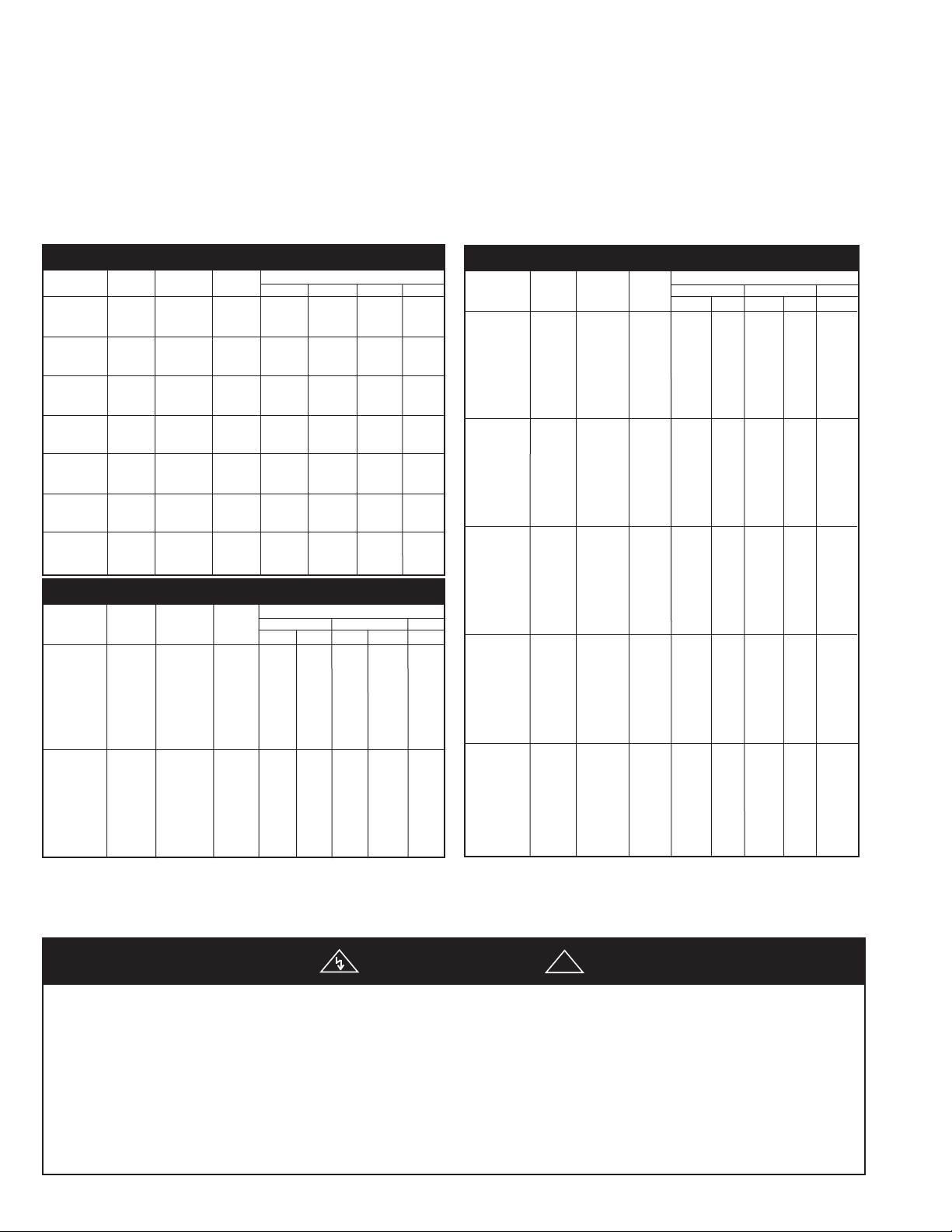
SPECIFICATIONS
Table A
Model CPH05A, DPH05A (H=5-1/2”; D=3”)
Catalog Total Amperage
Number* Length Watts/Ft. Watts 120V 208V 240V 277V
05A-2125 125 250 2.4 1.2 1.0 0.9
05A-2188 28” 188 375 3.1 1.8 1.6 1.4
05A-2250 250 500 4.2 2.4 2.1 1.8
5A-3125 125 375 3.1 1.8 1.6 1.4
0
05A-3188 3’ 188 564 4.7 2.7 2.4 2.0
05A-3250 250 750 6.2 3.6 3.1 2.7
05A-4125 125 500 4.2 2.4 2.1 1.8
05A-4188 4’ 188 750 6.2 3.6 3.1 2.7
5A-4250 250 1000 8.3 4.8 4.2 3.6
0
05A-5125 125 625 5.2 3.0 2.6 2.2
05A-5188 5’ 188 940 7.8 4.5 3.9 3.4
05A-5250 250 1250 10.4 6.0 5.2 4.5
5A-6125 125 750 6.2 3.6 3.1 2.7
0
05A-6188 6’ 188 1125 9.4 5.4 4.7 4.1
05A-6250 250 1500 12.5 7.2 6.2 5.4
5A-8125 125 1000 - 4.8 4.2 3.6
0
5A-8188 8’ 188 1500 - 7.2 6.2 5.4
0
05A-8250 250 2000 - 9.6 8.3 7.2
05A-10125 125 1250 - 6.0 5.2 4.5
05A-10188 10’ 188 1875 - 9.0 7.8 6.7
05A-10250 250 2500 - 12.0 10.4 9.0
Model CPH07A, DPH07A (H=7”; D=5”)
Catalog Total Amperage
Number* Length Watts/Ft. Watts 208V 240V 277V
07A-2125 125 250 1.2 - 1.0 - 0.9
07A-2188 188 375 1.8 - 1.6 - 1.4
07A-2250 250 500 2.4 - 2.1 - 1.8
07A-2375 375 750 3.6 - 3.1 - 2.7
07A-2500 28” 500 1000 4.8 - 4.2 - 3.6
07A-2564 564 1125 5.4 3.1 4.7 2.7 4.0
07A-2625 625 1250 6.0 3.5 5.2 3.0 4.5
07A-2750 750 1500 7.2 4.2 6.2 3.6 5.4
07A-3125 125 375 1.8 - 1.6 - 1.4
07A-3188 188 564 2.7 - 2.4 - 2.0
07A-3250 250 750 3.6 - 3.1 - 2.7
07A-3375 3’ 375 1125 5.4 - 4.7 - 4.0
07A-3500 500 1500 7.2 - 6.2 - 5.4
07A-3564 564 1690 8.1 4.7 7.4 4.3 6.1
07A-3625 625 1875 9.0 5.2 7.8 4.5 6.7
07A-3750 750 2250 11.0 6.5 9.4 5.4 8.1
1Ø 3Ø 1Ø 3Ø 1Ø
Note:
It is advisable to store cartons in a central area to be
drawn upon as needed per room requirements. If called for on
order, the cartons will have been tagged with proper room
number.
Table A (continued)
Model CPH07A, DPH07A (H=7”; D=5”) (Cont.)
Catalog Total Amperage
Number* Length Watts/Ft. Watts 208V 240V 277V
07A-4125 125 500 2.4 - 2.1 - 1.8
07A-4188 188 750 3.6 - 3.1 - 2.7
07A-4250 250 1000 4.8 - 4.2 - 3.6
07A-4375 375 1500 7.2 - 6.2 - 5.4
07A-4500 4’ 500 2000 9.6 - 8.3 - 7.2
07A-4564 564 2250 10.8 6.2 9.4 5.4 8.0
07A-4625 625 2500 12.0 6.9 10.4 6.2 9.0
07A-4750 750 3000 14.4 8.3 12.5 7.2 10.8
07A-5125 125 625 3.0 - 2.6 - 2.2
07A-5188 188 940 4.5 - 3.9 - 3.4
07A-5250 250 1250 6.0 - 5.2 - 4.5
07A-5375 5’ 375 1875 9.0 - 7.8 - 6.7
07A-5500 500 2500 12.0 - 10.4 - 9.0
07A-5564 564 2820 13.5 7.8 11.8 6.8 10.2
07A-5625 625 3125 15.0 8.6 13.0 7.5 11.3
07A-5750 750 3750 18.0 10.4 15.6 9.0 13.5
07A-6125 125 750 3.6 - 3.1 - 2.7
07A-6188 188 1125 5.4 - 4.7 - 4.0
07A-6250 250 1500 7.2 - 6.2 - 5.4
07A-6375 6’ 375 2250 10.8 - 9.4 - 8.1
07A-6500 500 3000 14.4 - 12.5 - 10.8
07A-6564 564 3380 16.2 9.4 14.1 8.1 12.2
07A-6625 625 3750 18.0 10.4 15.6 9.3 13.5
07A-6750 750 4500 21.6 12.5 18.7 10.8 16.2
07A-8125 125 1000 4.8 - 4.2 - 3.6
07A-8188 188 1500 7.2 - 6.2 - 5.4
07A-8250 250 2000 9.6 - 8.3 - 7.2
07A-8375 8’ 375 3000 14.4 - 12.5 - 10.8
07A-8500 500 4000 19.2 - 16.7 - 14.4
07A-8564 564 4500 21.6 12.5 18.7 10.8 16.2
07A-8625 625 5000 24.0 13.9 20.8 12.4 18.0
07A-8750 750 6000 28.6 16.5 25.0 14.4 21.6
07A-10125 125 1250 6.0 - 5.2 - 4.5
07A-10188 188 1875 9.0 - 7.8 - 6.7
07A-10250 250 2500 12.0 - 10.4 - 9.0
07A-10375 10’ 375 3750 18.0 - 15.6 - 13.5
07A-10500 500 45000 24.0 - 20.8 - 18.0
07A-10564 564 5640 27.2 15.7 23.5 13.6 20.4
07A-10625 625 6250 30.0 17.4 26.0 15.0 22.6
07A-10750 750 7500 36.6 20.8 31.3 18.1 27.0
1Ø 3Ø 1Ø 3Ø 1Ø
INSTALLATION
WARNING
Warningto property, read, understand and follow the below special
instructions:
1. All wiring procedures and connections must be in accor-
2. Do not install heaters against combustible low-density cellu-
3. Do not install heaters below electrical convenience recepta-
To reduce the risk of fire, electric shock and damage
dance with the National Electrical Code (NEC) and local
codes.
lose fiberboard surfaces.
cles (outlets).
!
4. To reduce the risk of fire, do not store or use gasoline or
other flammable vapors or liquids in the vicinity of the
heater.
CAUTION
5.
- Heater operates at High Temperatures. Keep
Electrical Cords, Drapes and Other Furnishings Away From
Heater. Maintain a minimum of 4 inches (102 mm) clearance from all exposed heater surfaces (top and front) at all
times.
2
Page 3
Rough-in Wiring
1. Branch circuits for the heaters shall be enclosed in 1” rigid
conduit for 05A heaters, or 1-1/4” rigid conduit for 07A
heaters.
2. Run branch circuit of proper voltage and wire size, in rigid
conduit, to location of left or right junction box as indicated
on heater wiring diagram. Wire entry to heater is through
either end pedestal.
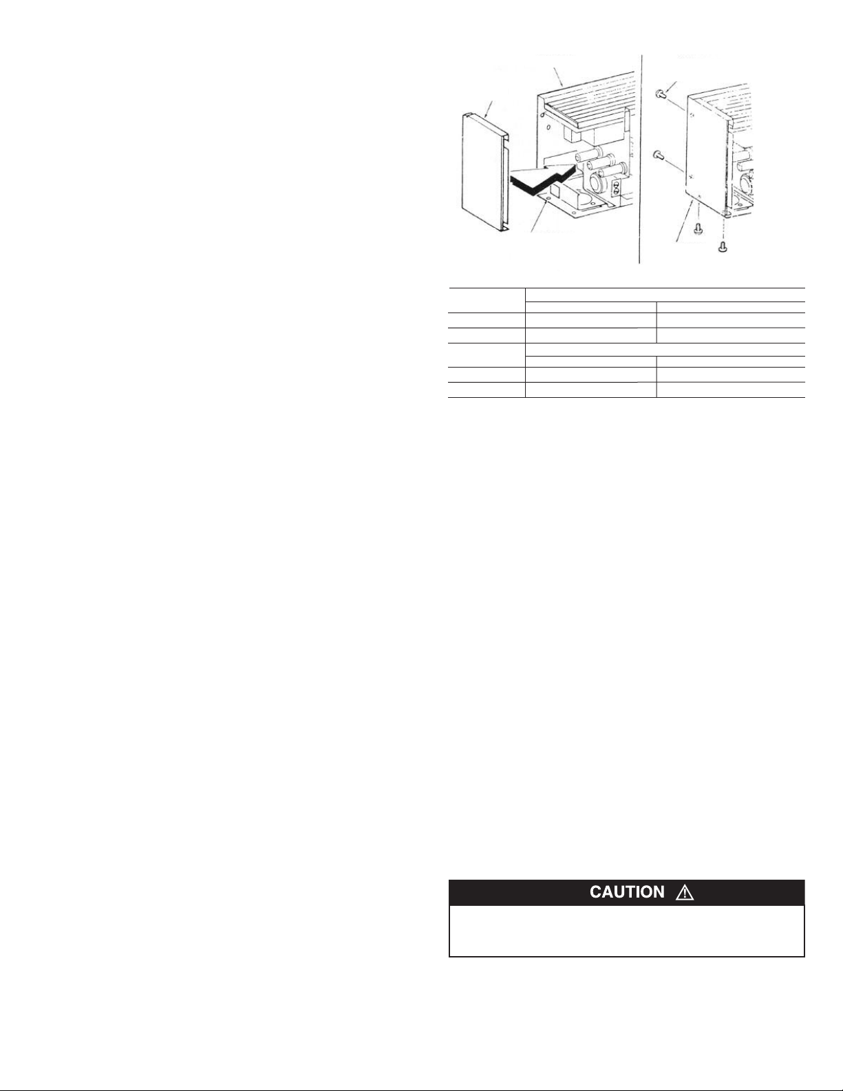
Note
When pedestal is not used for wire entry, pedestal base
must be covered with cover plate (supplied with pedestal). See
Figure 2.
3. When installing heaters on existing floors, the threaded end
of the rigid conduit must extend 7/8” to 1” above finished
concrete. Conduit must be threaded a minimum of 3/8”.
4. Basic heaters are prewired and can be connected to branch
circuit at either end. Heaters with controls are prewired for
connection to branch circuit at one end only (refer to heater
wiring diagram), however, heater can be wired from opposite
end by running wires through heater wireway.
5. If it is necessary to run wires through the heater wire way,
use Table B to size the field installed wiring.
6. The factory installed wires in the heater wireway can be
loaded up to 35 amps in 05A units and up to 45 amps in 07A
units. Refer to Table C and D for maximum length of heater
run when the heaters are connected in parallel.
TABLE D. Maximum Length of Heater Run
(07A - 1Ø and 3Ø)
Watts/Ft. of Maximum Allowable Length of Heater Run (Feet)
the Heaters 208 Volts 208 Volts 240 Volts 240 Volts 277 Volts
1Ø 3Ø 1Ø` 3Ø 1Ø
125 74 - 86 - 99
188 49 - 57 - 66
250 37 - 43 - 49
376 24 - 28 - 33
500 18 - 21 - 24
564 16 27 19 32 22
625 14 24 17 29 19
750 12 20 14 24 16
7. Standard 75˚C wiring must be used in junction boxes,
wire-
way and blank sections.
Room Layout
Refer to heating plans for exact room arrangements of heaters
(with or without thermostat and/or relays and/or switches and
accessories.)
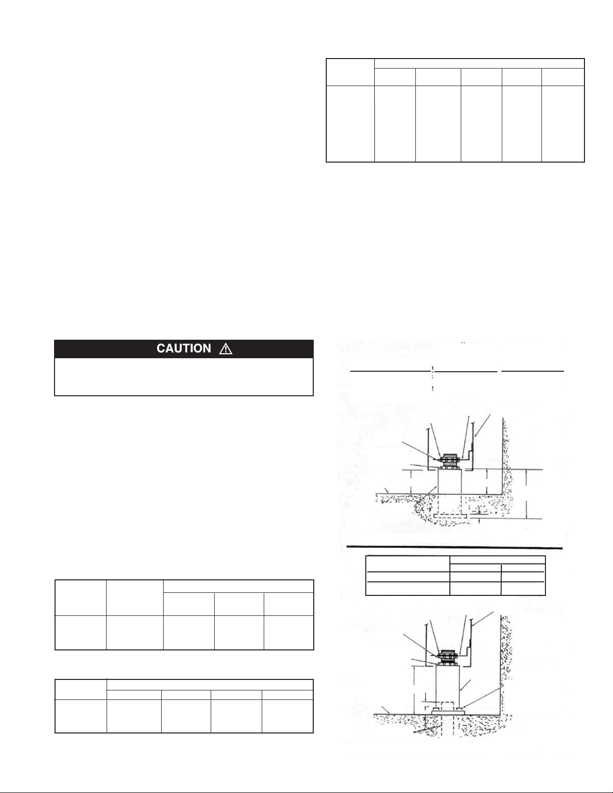
Mounting Height
Refer to Figure 1a. for typical mounting of heaters and pedestals
imbedded in floor; refer to Figure 1b. for surface-mounted
heaters and pedestals.
Note:
Up to 3/4” thick floor covering, such as carpet, tiles,
linoleum, etc., may be installed around and under the heater.
IF THE FACTORY INSTALLED WIRES IN THE WIREWAY
ARE USED TO CONNECT THE BUILT-IN CONTROLS, LIMIT
THE MAXIMUM CURRENT TO THE VALUES LISTED
Thermostat
24 amps @ 120-240 VAC
22 amps @ 277 VAC
Pilot duty– 125 VAC (all voltages)
Transformer relay
05A units: 22 amps @ 120-240 VAC
19 amps @ 277 VAC
07A Units: 25 AMPS @ 120-240 VAC
22 AMPS @ 277 VAC
Power relay
25 amps @ 120-277 VAC- see wiring diagram on heater
Disconnect switch
20 amps @ 120-277 VAC
Table B. Sizing Field Installed Wiring
Copper Maximum no.
wire size of wires Up to 3 4 to 6 7 thru 9
75º C in wireway Conductors Conductors Conductors
No. 12 AWG 9 11.5 amps 9.3 amps 8.1 amps
No. 10 AWG 8 17.4 amps 14.0 amps 12.1 amps
No. 8 AWG 4 24.0 amps 21.0 amps –
Maximum allowable current
Table C. Maximum Length of Heater Run
(05A-1Ø)
Watts/Ft. of Maximum allowable length of heater run (feet)
the heaters 120 Volts 208 Volts 240 Volts 277 Volts
125 33 58 67 77
188 22 38 44 51
250 16 29 33 38
Note:
For mix of watt densities, calculate amp draw. Do not
exceed values indicated in step 6 above.
Heater Capacity
(Watts.Ft. Heater Length)
125, 188 and 250 Watts/Ft.
376, 500, 564, 625 and 750
Watts/Ft.
Locknut
Leveling
Nut
Locknut (Do
Not Loosen
Or Remove)
Floor
Line
A
Pedestal
Figure 1a. Pedestal Imbedded in Floor
Heater Catalog Number Height Above Floor (Dim. “A)
05A 2-5/8” 3-3/8”
07A 3-7/8” 4-5/8”
Leveling
Nut
Locknut (Do
Not Loosen
Or Remove)
Rigid
Conduit
A
Floor
Line
Figure 1b. Surface-Mounted Pedestal
3
Dimension “A”
(Minimum Mounting
Height Above Floor)
Locknut
Heater
1-3/4”
3”
Welded
Bracket
3/8”
Min. Max.
Welded
Bracket
Pedestal
Heater
B
Heater
Pedestal
Dimension “B”
(Minimum Height
Above Floor)
2”
3-1/4”
2-7/8” (5” Heaters)
4-1/8” (7” Heaters)
Base Mounting
Holes - 1/4” DIa.
(Suitable
Fasteners By
Others)
Page 4
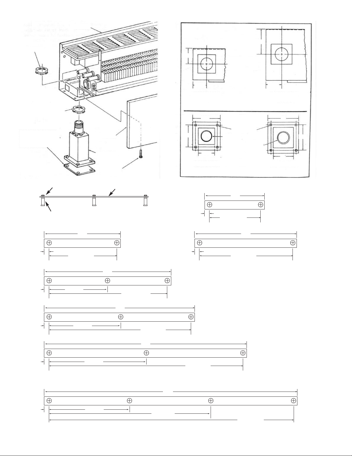
ocknut
L
Housing
-7/16”
1
2
-1/2”
Cover Plate (Used
Only When Pedestal Is
Not Used For Wire
Entry)
Figure 2.
1-7/16” (05A)
1-9/16” (07A)
Leveling
Nut
ocknut
L
Pedestal
Cover
Pedestal
Cover
Mounting
Screws
ypical Set-Up of Heater
T
edestal Using Jigs To
P
Maintain Proper Positioning
During Concrtete Pouring.
36”
33-1/8” (05A)
32-7/8” (07A)
ooden Jig
W
3-Foot Heater
1-7/16”
BOTTOM OF
05A HEATER
Figure 3a. End Pedestal Locations
2.75”
.125”
2
.625”
1
05A PEDESTAL
Figure 3b. Pedestal Details
1-7/16” (05A)
1-9/16” (07A)
1-7/16” (05A)
1-9/16” (07A)
0.250” Dia.
ounting Holes
M
1” Threaded
Pipe
28”
25-1/8” (05A)
24-7/8” (07A)
45-1/8” (05A)
44-7/8” (07A)
1-1/4” Threaded
Pipe
48”
1-9/16”
BOTTOM OF
07A HEATER
3”
”
2
07A PEDESTAL
28-Inch Heater
4-Foot Heater
2.5”
1-7/16” (05A)
1-9/16” (07A)
1-7/16” (05A)
1-9/16” (07A)
1-7/16” (05A)
1-9/16” (07A)
1-7/16” (05A)
1-9/16” (07A)
Figure 4.
28-13/16”
32-13/16”
44-13/16”
36-13/16”
60”
57-1/8” (05A)
56-7/8” (07A)
72”
69-1/8” (05A)
68-7/8” (07A)
94”
76-13/16”
5-Foot Heater
120”
4
6-Foot Heater
93-1/8” (05A)
92-7/8” (07A)
NOTE: HOLES IN JIGS SHOULD BE
1-3/8” FOR 05A HEATERS, OR 1-11/16”
FOR 07A HEATERS.
* WHEN BUTTING HEATERS,
LEAVE A 1/16” GAP BETWEEN
HEATERS TO ALLOW FOR
EXPANSION.
8-Foot Heater
10-Foot Heater
117-1/8” (05A)
116-7/8” (07A)
Page 5
Pedestal Installation
(Surface-Mounted to Existing Floor)
Note:
For ease of installation, it is important that the sequence
of operations indicated below be followed in order.
1. Remove front cover by removing mounting screws (Fig. 2)
2. Remove the top lock nut and the leveling nut from each
pedestal. (Do not loosen or remove the bottom lock nut.)
3. Screw one pedestal onto threaded rigid conduit protruding
from floor.
4. Install remaining pedestal(s) in heater and secure by
installing lock nut finger tight.
5. Install heater onto the pedestal which is screwed on the rigid
conduit. Position heater in desired location and mark
pedestal mounting hole locations on floor. Then remove the
heater and the one pedestal from the rigid conduit.Remove
the remaining pedestal(s) from the heater.
6. Drill holes in floor (Fig. 3b) and install threaded inserts (or
equivalent for 1/4” mounting bolts (inserts and bolts supplied
by installer.)
7. Reinstall the one pedestal on the rigid conduit, then secure
all other pedestals (with cover plates) to the floor with four
1/4” bolts through each pedestal flange.
Pedestal Installation
(Imbedded in New Concrete Floor)
When a heater installation is to be imbedded in a new concrete
floor, the pedestals are first installed in the concrete, then the
heater installed after the concrete has set. It is imperative that
the pedestals be installed in perfect alignment so that the holes
in order to achieve the required alignment, it is recommended
that the pedestals be held in place by the use of jigs during the
concrete pour. The jigs should be constructed of good quality 1”
x 4” lumber as shown in Figure 4. The pedestals are installed in
the jigs and then positioned for the concrete pour. One end
pedestal must be screwed onto rigid wall conduit so that the
mounting height requirements in Figure 1a are met after pouring
of the finished floor. (The method of securing the pedestals and
jigs in place during the pouring of the concrete is at the option of
the installer.) After the concrete has set, remove the jigs from
the pedestals and install the heater as indicated in steps Seven
or Eight.
Installation of Single Unit
Note:
For ease of installation, it is important that the sequence
of operations below be followed in order.
1. Remove front cover by removing mounting screws (Fig. 2)
2. Install end caps (must be purchased separately) on both
ends of the heater housing. Refer to Figure 5 (Type CPH
and DPH) for details of end cap installation.
3. Install leveling nut on each installed pedestal, then position
heater on pedestals. Adjust the leveling nuts until the heater
is level and at the desired mounting height. Then install and
tighten the pedestal lock nuts.
4. Run proper size branch circuit to the junction box through the
appropriate end pedestal.
5. Following the wiring diagram secured to the heater, make
electrical connections.
6. Replace front cover and secure with mounting screws. (See
Figure 2.)
7. If the heater is equipped with a built-in thermostat, adjust the
shaft to the mid-range and let the heater run for a few hours.
ousing
End
Cap
H
Accessory
Mounting
Holes
nd Cap
E
ounting
M
crews
S
End Cap Data
Description CPH05A CPH07A
End Cap Left CPH05-ECL(R) CPH07-ECL(R)
End Cap Right CPH05-ECR(R) CPH07-ECR(R)
End Cap Left DSH05-ECL(R) DSH07-ECL(R)
End Cap Right DSH05-ECR(R) DSH07-ECR(R)
(R) Suffix on catalog number refers to accessories with 120 VAC receptacle.
Heater Catalog Number
Heater Catalog Number
DPH05A DPH07A
Figure 5. (Type CPH and DPH Only)
If the room temperature is too hot,
rotate the shaft counterclockwise; if too cool, rotate the shaft clockwise until
a comfortable temperature is obtained. Let room temperature stabilize after each setting change.
Note:
The thermostat adjustment shaft and the disconnect
switch are accessible through the grille openings at the left end
of the heater.
Installation of Multiple Units
Note:
For ease of installation, it is important that the sequence
of operations indicated below be followed in order.
1. Remove front cover by removing mounting screws (Figure
2.)
2. Install end caps on the outer end of the first and last heater
(or blank section ) in a run using four No. 6 screws supplied
with end caps. (Refer to Figure 5a or 5b for details of end
cap installation.)
3. Run proper size branch circuit to the junction box through
heaters and blank sections (if applicable) on pedestals.
Note (Type CPH and DPH only):
end, be sure to position heaters carefully to insure proper alignment. Leave a 1/16” gap between heaters to allow for expansion.
4. Adjust the leveling nuts until the heaters are level and at the
desired mounting height. Then install and tighten the
pedestal lock nuts.
DO NOT OPERATE THE HEATERS UNLESS THE OUTER
END OF THE LAST HEATERS (OR BLANK SECTIONS) IN
THE RUN ARE CLOSED WITH END CAPS.
Note
: 75˚C field wiring may be run through the blank section
wireway.
5
When butting heaters end to
Page 6
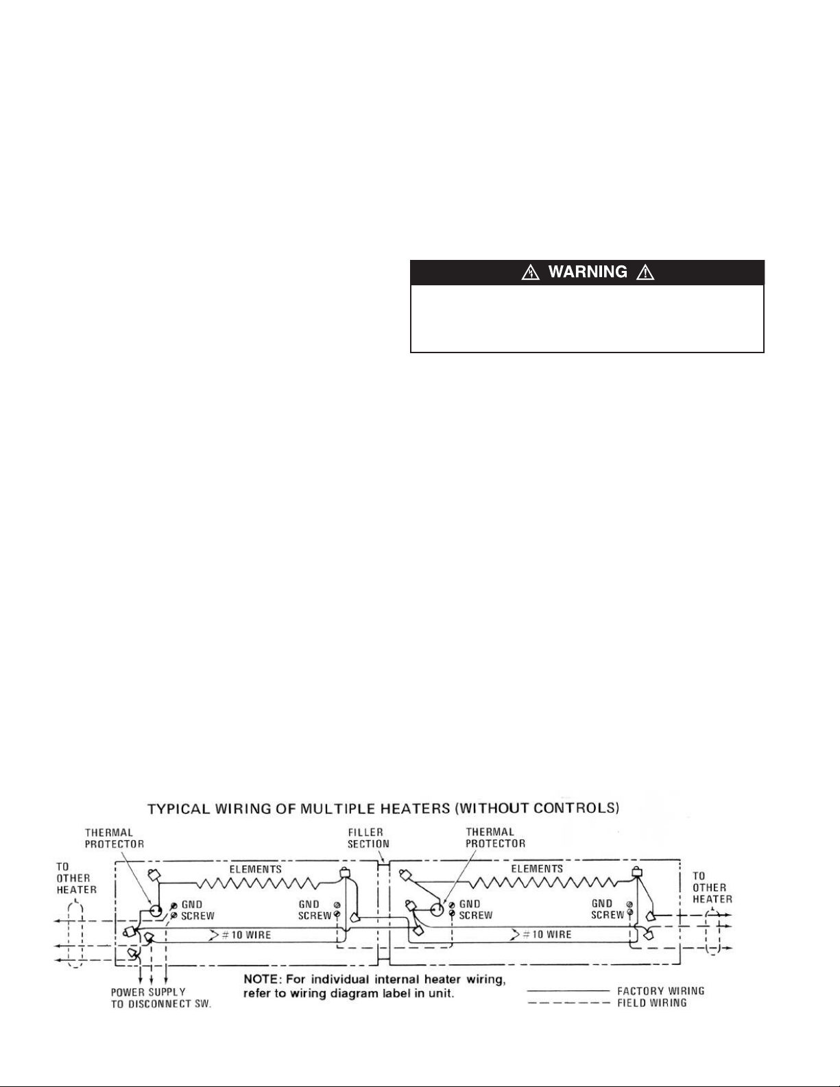
5. Following the wiring diagram secured to the heater, make the
electrical connections. Refer to Figure 7 to connect the other
heaters in parallel. Grounding of the other heaters is accomplished by connecting a jumper wire (not supplied) between
the two adjacent heaters.
6. Replace front covers, and secure with mounting screws.
(Figure 2.)
7. If the heaters are equipped with built-in thermostat, adjust
the shaft to the mid-range and let the heaters run for a few
hours. If the room temperature is too hot, rotate the shaft
counterclockwise; if too cool, rotate the shaft clockwise until
a comfortable temperature is obtained. Let room temperature
stabilize after each setting change.
Note:
The thermostat adjustment shaft and the disconnect
switch are accessible through the grille openings at the left end
of the heater.
OPERATION
1. This heater must be properly installed before it is used.
2. If the heater is equipped with a built-in thermostat, adjust the
shaft to the mid-range and let the heater run for a few hours.
If the room temperature is too hot, rotate the shaft counterclockwise; if too cool, rotate the shaft clockwise until a comfortable temperature is obtained. Let room temperature stabilize after each setting change. The heater will automatically cycle around this set point on the thermostat.
Note:
If a thermostat or disconnect switch is provided in the
heater, these components are accessible through the grille
openings at the left or right end of the heater.
3. There are safety over-temperature limiting devices inside the
heater. These safety devices are there to turn off the heater
automatically in the event of an over-temperature condition.
These devices are not to be tampered with or disconnected
from the electrical system. If the heater is installed correctly
and wired to the correct voltage, these devices should never
operate to turn off the heater. If this device is cycling the
heater off and on, turn off power to the heater and and have
the heater serviced by qualified service personnel.
MAINTENANCE
1. The user can perform periodic cleaning of the outer cabinet.
All other servicing is to be done by qualified service personnel.
2. The finish of the heater may be cleaned with a slightly damp
rag if desired.
3. Because of the convection heating principle which depends
on air circulation through the heater, dust can collect
between the fins. The heater should be cleaned annually for
maximum efficiency.
4. To remove the front cover, remove attachment screws at the
bottom of the front cover.
BEFORE REMOVING THE FRONT COVER FOR SERVICING
OR CLEANING, BE SURE POWER HAS BEEN TURNED OFF
AT THE CIRCUIT BREAKER PANEL AND THE HEATER ELEMENT IS COOL.
5. A vacuum cleaner with a brush attachment may be used for
cleaning of the element fins.
6. Replace front cover, (using the screws provided), restore
power and check heater for proper operation.
Figure 7 - Wiring Diagram
6
Page 7
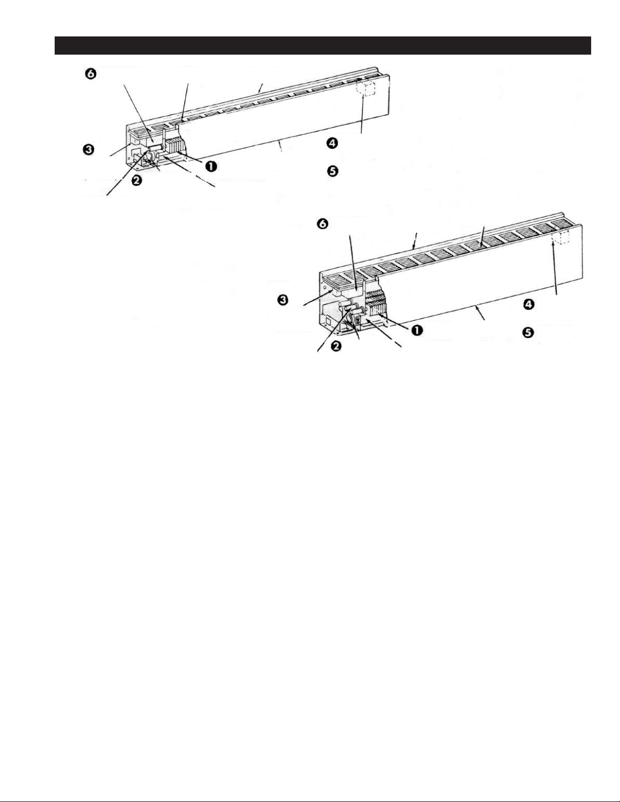
RENEWAL PARTS IDENTIFICATION CPH
Thermostat
(Optional)
Disconnect
witch
S
(Optional)
Element Bushing
1213-2000-001
2501-0257-VAR
Overload
Protector
520-0007-VAR
4
CPH07A
*Grille
*Back Panel
2701-0765-VAR
eating
H
lement
E
Wireway Cover
6405-0053-VAR
Element Bushing
*Front Cover
1402-0316-VAR
Disconnect
Switch
Optional)
(
1213-2000-000
Transformer
Relay
Optional)
(
ower Relay
P
Optional)
(
Thermostat
(Optional)
verload
O
Protector
4520-0007-VAR
*Back Panel
701-0766-VAR
2
Wireway Cover
6405-0053-VAR
CPH05A
eating
H
Element
Grille
*
2501-0251-VAR
Front Cover
*
1402-0315-VAR
Transformer
elay
R
(Optional)
Power Relay
(Optional)
7
Page 8
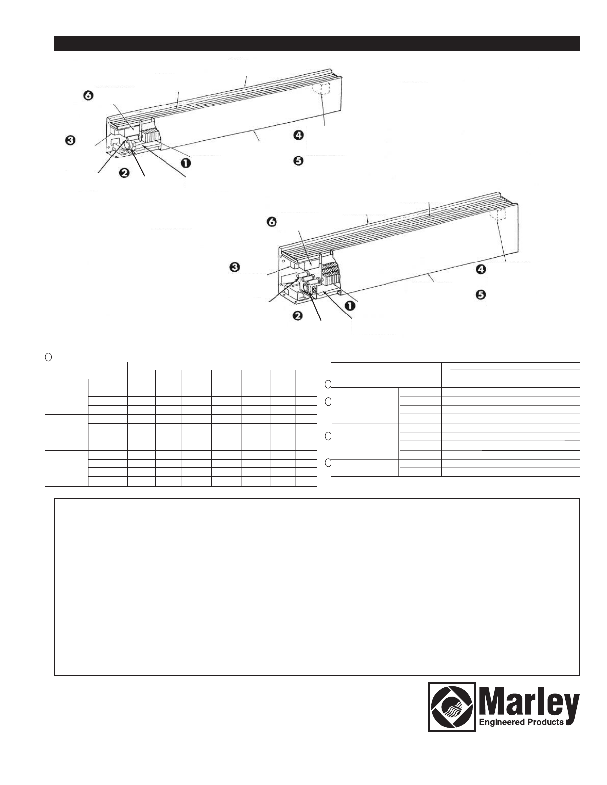
isconnect
D
Switch
(Optional)
lement Bushing
E
1213-2000-001
Thermostat
Optional)
(
*Grille
2501-0252-VAR
verload
O
Protector
4520-0007-VAR
DPH07A
RENEWAL PARTS IDENTIFICATION DPH
*Back Panel
2701-0765-VAR
DPH05A
Transformer
Relay
Optional)
(
Power Relay
(Optional)
Optional)
Overload
rotector
P
4520-0007-VAR
*Back Panel
701-0766-VAR
2
eating
H
Element
ireway Cover
W
6405-0053-VAR
2501-0251-VAR
Heating
Element
Wireway Cover
6405-0053-VAR
Disconnect
Optional)
(
Element Bushing
213-2000-000
1
*Front Cover
402-0316-VAR
1
Switch
Thermostat
(
*Grille
*Front Cover
402-0315-VAR
1
Transformer
elay
R
(Optional)
Power Relay
(Optional)
1
Heating Element (Part No. Prefix 1802-2001)
Heater Length
Description 28” 3’ 4’ 5’ 6’ 8’ 10’
120 Volts 085 087 089 091 093 -125 W/Ft. 208 Volts 086 088 090 092 091 095 096
per Element 240 Volts 048 054 060 066 072 077 081
277 Volts 049 055 061 067 073 078 082
120 Volts 005 011 017 023 029 -188 W/Ft. 208 Volts 002 008 014 020 026 032 036
per Element 240 Volts 001 007 013 019 025 031 035
277 Volts 000 006 012 018 024 030 034
120 Volts 004 010 016 022 028 -250 W/Ft. 208 Volts 003 009 015 021 027 033 037
per Element 240 Volts 002 008 014 020 026 032 036
277 Volts 001 007 013 019 025 031 035
Built-In Controls (Optional)
Description 07A and 14A Units 05A Units
Disconnect Switch 5216-0124-000 5216-0124-000
3
4
Transformer Relay 208 Volt R13700002B002 410043002
5
Power Relay 120 Volt 5018-2006-001 5018-2006-001
6
Thermostat 1 Pole 5813-0024-000 5813-0024-000
120 Volt R13700002B001 410043001
240 Volt R13700002B003 410043003
277 Volt R13700002B004 410043004
24 Volt 5018-2006-000 5018-2006-000
208/240 Volt 5018-2006-002 5018-2006-002
277 Volt 5018-2006-003 5018-2006-003
2 Pole 5812-0023-000 5813-0023-000
Part Number
LIMITED WARRANTY
All products manufactured by Marley Engineered Products are warranted against defects in workmanship and materials for one year from date of installation, except
heating elements which are warranted against defects in workmanship and materials for five years from date of installation. This warranty does not apply to damage from
accident, misuse, or alteration; nor where the connected voltage is more than 5% above the nameplate voltage; nor to equipment improperly installed or wired or
maintained in violation of the product’s installation instructions. All claims for warranty work must be accompanied by proof of the date of installation.
The customer shall be responsible for all costs incurred in the removal or reinstallation of products, including labor costs, and shipping costs incurred to return products
to Marley Engineered Products Service Center. Within the limitations of this warranty, inoperative units should be returned to the nearest Marley authorized service center or the Marley Engineered Products Service Center, and we will repair or replace, at our option, at no charge to you with return freight paid by Marley. It is agreed that
such repair or replacement is the exclusive remedy available from Marley Engineered Products.
THE ABOVE WARRANTIES ARE IN LIEU OF ALL OTHER WARRANTIES EXPRESSED OR IMPLIED, AND ALL IMPLIED WARRANTIES OF MERCHANTABILITY AND
FITNESS FOR A PARTICULAR PURPOSE WHICH EXCEED THE AFORESAID EXPRESSED WARRANTIES ARE HEREBY DISCLAIMED AND EXCLUDED FROM
THIS AGREEMENT. MARLEY ENGINEERED PRODUCTS SHALL NOT BE LIABLE FOR CONSEQUENTIAL DAMAGES ARISING WITH RESPECT TO THE
PRODUCT, WHETHER BASED UPON NEGLIGENCE, TORT, STRICT LIABILITY, OR CONTRACT.
Some states do not allow the exclusion or limitation of incidental or consequential damages, so the above exclusion or limitation may not apply to you. This warranty gives
you specific legal rights, and you may also have other rights which vary from state to state.
For the address of your nearest authorized service center, contact Marley Engineered Products in Bennettsville, SC, at 1-800-642-4328. Merchandise returned to the factory must be accompanied by a return authorization and service identification tag, both available from Marley Engineered Products. When requesting return authorization,
include all catalog numbers shown on the products.
HOW TO OBTAIN WARRANTY SERVICE AND
WARRANTY PARTS PLUS GENERAL INFORMATION
1. Warranty Service or Parts
2. Purchase Replacement Parts
3. General Product Information
1-800-642-4328
1-800-654-3545
www.marleymep.com
Part No. 5200-2109-002
Note:
When obtaining service always have the
following:
1. Model number of the product
2. Date of manufacture
3. Part number or description
ECR 39036
02/11
470 Beauty Spot Rd. East
Bennettsville, SC 29512 USA
Page 9

Calefactor de convección
comercial de pedestal (Tipo
CPH)
Calefactores de convección
decorativos de pedestal (Tipo
DPH)
CPH y DPH
Calefactor de convección
INSTRUCCIONES IMPORTANTES
Estimado Propietario,
¡Felicitaciones! Gracias por comprar este nuevo calefactor fabricado por Marley Engineered Products. Usted
ha hecho una sabia inversión al seleccionar el producto de la más alta calidad en la industria de la calefacción. Por favor lea cuidadosamente las instrucciones de instalación y mantenimiento incluidas en este manual. Así podrá disfrutar de años de calefacción confortable y eficiente con este producto de Marley Engineered
Products ... el líder de la industria en diseño, fabricación, calidad y servicio.
ADVERTENCIA
Lea cuidadosamente
darle a solucionar las dificultades que pudieran surgir durante la
instalación de estos Calefactores de Pedestal. El estudio previo de
estas instrucciones le ahorrará considerable tiempo y dinero en el
futuro. Estos Calefactores de Pedestal están diseñados para una
instalación fácil y económica. Siga estas instrucciones para mantener
su tiempo de instalación en un mínimo.
1. Lea todas las instrucciones antes de usar el calefactor.
Peligro de incendio o descarga eléctrica
2.
ble descarga eléctrica, primero verifique que la electricidad está
apagada en el interruptor principal antes de cablear. Todo el
cableado debe realizarse de acuerdo con el Código Eléctrico
Nacional (NEC) y los códigos locales aplicables, y toda la instalación del calefactor debe conectarse a tierra como precaución
contra una posible descarga eléctrica.
3. Antes de energizar, verifique el voltaje de suministro para asegurarse que es igual al indicado en la placa de datos del calefactor.
4. No instale calefactores contra superficies combustibles de tabla
de fibra de celulosa de baja densidad.
5. Debido a las variaciones en las composiciones del vinilo y su
posibilidad de decoloramiento, al instalar sobre cubiertas de
pared de vinilo o debajo de adornos de vinilo de ventanas,
podría requerirse el uso de separadores (SO1A y SO2A) y/o
especificar una unidad con densidad de potencia (watts) inferior.
– Estas instrucciones están escritas para ayu-
– Para evitar una posi-
... Los Empleados de
Marley Engineered Products
!
6. Los extremos del calefactor deben quedar completamente cerrados mediante el uso de calefactores contiguos, tapas de
extremo, u otros accesorios.
7. No coloque el calefactor debajo de un tomacorriente eléctrico.
8. Un calefactor tiene en su interior piezas calientes, piezas que
forman arcos eléctricos o piezas que producen chispa. No utilice
esta unidad en áreas donde se utiliza o almacena gasolina, pintura, o líquidos inflamables. No instale este calefactor en posición invertida (boca abajo) o donde exista agua.
9. Este calefactor está caliente cuando está en uso. Para evitar
quemaduras, no permita que la piel desnuda haga contacto con
las superficies calientes. Mantenga alejados del calefactor los
materiales combustibles tales como muebles, almohadas, ropa
de cama, papeles, ropa y cortinas.
10. Para evitar un posible incendio, no obstruya de ninguna manera
las entradas o escape de aire.
11. No inserte ni permita que objetos extraños ingresen a las aberturas de ventilación o de escape, ya que esto podría causar una
descarga eléctrica, incendio, o podría dañar el calefactor.
12. Ante de utilizar el calefactor, deseche las almohadillas de
empaque.
Además, vea las advertencias adicionales indicadas en este manual.
GUARDE ESTAS INSTRUCCIONES
Page 10

RECEPCIÓN
1. Cada Calefactor tipo Pedestal se envía en dos cajas de cartón. Una
caja contiene el calefactor, la otra caja contiene los pedestales.
2. En el momento de enviar el material, éste estaba en buenas condiciones; y Marley Engineered Products guarda el conocimiento de
embarque autorizado, por lo tanto, cualquier daño oculto debe
reportarse inmediatamente a la empresa de transporte para inspección y resolución.
ESPECIFICACIONES
Tabla A
Modelo CPH05A, DPH05A (Alt.=51/2”; Prof.=3”)
Número de Watts/ Watts Amperaje
catálogo* Longitud Pie total 120 V 208 V 240 V 277 V
05A-2125 125 250 2.4 1.2 1.0 0.9
05A-2188 28” 188 375 3.1 1.8 1.6 1.4
05A-2250 250 500 4.2 2.4 2.1 1.8
5A-3125 125 375 3.1 1.8 1.6 1.4
0
05A-3188 3’ 188 564 4.7 2.7 2.4 2.0
05A-3250 250 750 6.2 3.6 3.1 2.7
05A-4125 125 500 4.2 2.4 2.1 1.8
05A-4188 4’ 188 750 6.2 3.6 3.1 2.7
5A-4250 250 1000 8.3 4.8 4.2 3.6
0
05A-5125 125 625 5.2 3.0 2.6 2.2
05A-5188 5’ 188 940 7.8 4.5 3.9 3.4
05A-5250 250 1250 10.4 6.0 5.2 4.5
5A-6125 125 750 6.2 3.6 3.1 2.7
0
05A-6188 6’ 188 1125 9.4 5.4 4.7 4.1
05A-6250 250 1500 12.5 7.2 6.2 5.4
5A-8125 125 1000 - 4.8 4.2 3.6
0
5A-8188 8’ 188 1500 - 7.2 6.2 5.4
0
05A-8250 250 2000 - 9.6 8.3 7.2
05A-10125 125 1250 - 6.0 5.2 4.5
05A-10188 10’ 188 1875 - 9.0 7.8 6.7
05A-10250 250 2500 - 12.0 10.4 9.0
Modelo CPH07A, DPH07A (Alt.=7”; Prof.=5”)
Número de Watts/ Watts Amperaje
catálogo* Longitud Pie total 120 V 208 V 240 V 277 V
07A-2125 125 250 1.2 - 1.0 - 0.9
07A-2188 188 375 1.8 - 1.6 - 1.4
07A-2250 250 500 2.4 - 2.1 - 1.8
07A-2375 375 750 3.6 - 3.1 - 2.7
07A-2500 28” 500 1000 4.8 - 4.2 - 3.6
07A-2564 564 1125 5.4 3.1 4.7 2.7 4.0
07A-2625 625 1250 6.0 3.5 5.2 3.0 4.5
07A-2750 750 1500 7.2 4.2 6.2 3.6 5.4
07A-3125 125 375 1.8 - 1.6 - 1.4
07A-3188 188 564 2.7 - 2.4 - 2.0
07A-3250 250 750 3.6 - 3.1 - 2.7
07A-3375 3’ 375 1125 5.4 - 4.7 - 4.0
07A-3500 500 1500 7.2 - 6.2 - 5.4
07A-3564 564 1690 8.1 4.7 7.4 4.3 6.1
07A-3625 625 1875 9.0 5.2 7.8 4.5 6.7
07A-3750 750 2250 11.0 6.5 9.4 5.4 8.1
1Ø 3Ø 1Ø 3Ø 1Ø
Nota:
Se recomienda guardar las cajas de cartón en una área central
para ser utilizadas según se necesite, según los requisitos del salón. Si
se requiere en orden, la cajas de cartón tendrán que ser etiquetadas
con el número de salón apropiado.
Tabla A (continuación)
Modelo CPH07A, DPH07A (Alt.=7”; Prof.=5”) (Cont.)
Número de Watts/ Watts Amperaje
catálogo* Longitud Pie total 120 V 208 V 240 V 277 V
07A-4125 125 500 2.4 - 2.1 - 1.8
07A-4188 188 750 3.6 - 3.1 - 2.7
07A-4250 250 1000 4.8 - 4.2 - 3.6
07A-4375 375 1500 7.2 - 6.2 - 5.4
07A-4500 4’ 500 2000 9.6 - 8.3 - 7.2
07A-4564 564 2250 10.8 6.2 9.4 5.4 8.0
07A-4625 625 2500 12.0 6.9 10.4 6.2 9.0
07A-4750 750 3000 14.4 8.3 12.5 7.2 10.8
07A-5125 125 625 3.0 - 2.6 - 2.2
07A-5188 188 940 4.5 - 3.9 - 3.4
07A-5250 250 1250 6.0 - 5.2 - 4.5
07A-5375 5’ 375 1875 9.0 - 7.8 - 6.7
07A-5500 500 2500 12.0 - 10.4 - 9.0
07A-5564 564 2820 13.5 7.8 11.8 6.8 10.2
07A-5625 625 3125 15.0 8.6 13.0 7.5 11.3
07A-5750 750 3750 18.0 10.4 15.6 9.0 13.5
07A-6125 125 750 3.6 - 3.1 - 2.7
07A-6188 188 1125 5.4 - 4.7 - 4.0
07A-6250 250 1500 7.2 - 6.2 - 5.4
07A-6375 6’ 375 2250 10.8 - 9.4 - 8.1
07A-6500 500 3000 14.4 - 12.5 - 10.8
07A-6564 564 3380 16.2 9.4 14.1 8.1 12.2
07A-6625 625 3750 18.0 10.4 15.6 9.3 13.5
07A-6750 750 4500 21.6 12.5 18.7 10.8 16.2
07A-8125 125 1000 4.8 - 4.2 - 3.6
07A-8188 188 1500 7.2 - 6.2 - 5.4
07A-8250 250 2000 9.6 - 8.3 - 7.2
07A-8375 8’ 375 3000 14.4 - 12.5 - 10.8
07A-8500 500 4000 19.2 - 16.7 - 14.4
07A-8564 564 4500 21.6 12.5 18.7 10.8 16.2
07A-8625 625 5000 24.0 13.9 20.8 12.4 18.0
07A-8750 750 6000 28.6 16.5 25.0 14.4 21.6
07A-10125 125 1250 6.0 - 5.2 - 4.5
07A-10188 188 1875 9.0 - 7.8 - 6.7
07A-10250 250 2500 12.0 - 10.4 - 9.0
07A-10375 10’ 375 3750 18.0 - 15.6 - 13.5
07A-10500 500 45000 24.0 - 20.8 - 18.0
07A-10564 564 5640 27.2 15.7 23.5 13.6 20.4
07A-10625 625 6250 30.0 17.4 26.0 15.0 22.6
07A-10750 750 7500 36.6 20.8 31.3 18.1 27.0
1Ø 3Ø 1Ø 3Ø 1Ø
INSTRUCCIONES DE INSTALACIÓN
ADVERTENCIA
Advertenciadaño a la propiedad, lea, entienda y siga las siguientes instrucciones
especiales:
1. Todas las conexiones y procedimientos de cableado deben
realizarse de acuerdo con el Código Eléctrico Nacional (NEC) y los
códigos locales.
2. No instale calefactores contra superficies combustibles de tabla de
fibra de celulosa de baja densidad.
3. No instale los calefactores debajo de tomacorrientes eléctricos.
Para reducir el riesgo de incendio, descarga eléctrica y
!
4. Para reducir el riesgo de incendio, no almacene ni utilice gasolina
ni otros vapores o líquidos inflamables cerca del calefactor.
PRECAUCIÓN-
5.
Mantenga alejados del calefactor los cables eléctricos, cortinas y
muebles. Mantenga a todo momento un espacio libre mínimo de 4
pulgadas (102 mm) en todas las superficies expuestas del calefactor (superiores y delanteras).
10
El calefactor funciona a altas temperaturas.
Page 11

Preparación preliminar del cableado
1. Los circuitos de derivación para los calefactores deberán encerrarse
en conducto/tubo rígido de 1” para los calefactores 05A, ó conducto
rígido de 1-1/4” para los calefactores 07A.
2. Tienda un circuito de derivación de voltaje y tamaño de alambre
apropiados, dentro de conducto rígido, hasta el sitio de la caja de
conexiones izquierda o derecha según se indica en el diagrama de
cableado del calefactor. La entrada de alambres al calefactor es a
través de cualquier pedestal de extremo.
Nota-
Cuando el pedestal no se utiliza para la entrada de alambres, la
base del pedestal debe cubrirse con placa (suministrada con el
pedestal). Vea la Figura 2.
3. Al instalar calefactores sobre pisos existentes, el extremo roscado
del conducto rígido debe extenderse 7/8” a 1” por encima del concreto acabado. El conducto/tubo debe tener rosca de 3/8” como mínimo.
4. Los calefactores básicos están precableados y pueden conectarse
al circuito de derivación en cualquier extremo. Los calefactores con
controles están precableados para conexión con el circuito de
derivación en un (1) extremo únicamente (consulte el diagrama de
cableado del calefactor), sin embargo, el calefactor puede cablearse
desde el extremo opuesto tendiendo los alambres a través del conducto superficial de alambres del calefactor.
5. Si es necesario tender alambres a través del conducto superficial de
alambres del calefactor, utilice la Tabla B para dimensionar los
alambres instalables en campo.
6. Los alambres instalados en fábrica en el conducto superficial de
alambres del calefactor pueden cargarse hasta 35 amperios en las
unidades 05A y hasta 45 amperios en las unidades 07A. Consulte la
Tabla C y D para obtener la longitud máxima del cableado (tendido)
del calefactor cuando los calefactores se conectan en paralelo.
PRECAUCIÓN
SI LOS ALAMBRES INSTALADOS EN FÁBRICA EN EL CONDUCTO SUPERFICIAL DE ALAMBRES SE UTILIZAN PARA CONECTAR LOS CONTROLES INCORPORADOS, LIMITE LA CORRIENTE MÁXIMA A LOS VALORES INDICADOS
Termostato
Relé del transformador
Unidades 05A: 22 amps @ 120-240 VAC
Unidades 07A: 25 amps @ 120-240 VAC
24 amps @ 120-240 VAC
22 amps @ 277 VAC
Servicio piloto – 125 VAC
(todos los voltajes)
19 amps @ 277 VAC
22 amps @ 277 VAC
TABLA D. Longitud máxima del cableado del calefactor
(07A - 1Ø y 3Ø)
Watts/Pie. Longitud máxima permisible del cableado del calefactor (pies)
de los 208 Voltios 208 Voltios 240 Voltios 240 Voltios 277 Voltios
calefactores 1Ø 3Ø 1Ø` 3Ø 1Ø
125 74 - 86 - 99
188 49 - 57 - 66
50 37 - 43 - 49
2
76 24 - 28 - 33
3
00 18 - 21 - 24
5
564 16 27 19 32 22
625 14 24 17 29 19
750 12 20 14 24 16
7. Deben utilizarse alambres estándar para 75°C en las cajas de
conexiones, los conductos superficiales de alambres y las secciones
de espacios libres.
Disposición en salón
Consulte los planos de calefacción para obtener la disposición exacta
en salón de los calefactores (con o sin termostato y/o relés y/o interruptores y accesorios).
Altura de Montaje
Consulte la Figura 1a. para ver el montaje típico de calefactores y
pedestales incrustados en piso; consulte la Figura 1b. para ver
pedestales y calefactores montados en superficie.
Nota:
Puede instalarse cubierta de piso de hasta 3/4” de espesor, tal
como alfombra, baldosas, linóleo, etc. alrededor y debajo del calefactor.
Capacidad del calefactor
(Watts/Pie de
longitud de
calefactor)
25, 188 y 250 Watts/Pie
1
376, 500, 564, 625 y 750
Watts/Pie
Tuerca de
nivelación
Tuerca de fijación
(no aflojar ni
remover)
Línea de
piso
A
Pedestal
Tuerca de
fijación
Calefactor
Dimensión “A” (Altura
de montaje mínima
sobre el piso)
-3/4”
1
3”
Brazo
soldado
B
Pedestal
Dimensión “B”
(Altura mínima
sobre el piso)
2
3-1/4”
Calefactor
2-7/8” (Calefactores de 5”)
4-1/8” (Calefactores de 7”)
”
Relé de potencia
25 amps @ 120-277 VAC - vea el
diagrama de cableado en el calefactor
Interruptor de desconexión
Tabla B. Dimensionado de los alambres de instalación en campo
Tamaño de de alambres en
alambre de el conducto Hasta 3 4 a 6 7 a 9
cobre 75° C de alambres alambres alambres alambres
No. 12 AWG 9 11.5 A 9.3 A 8.1 A
No. 10 AWG 8 17.4 A 14.0 A 12.1 A
No. 8 AWG 4 24.0 A 21.0 A –
Tabla C. Longitud máxima del cableado del calefactor (05A-1Ø)
Watts/Pie. Longitud máxima permisible
de losdel cableado del calefactor (pies)
calefactores 120 Voltios 208 Voltios 240 Voltios 277 Voltios
125 33 58 67 77
188 22 38 44 51
250 16 29 33 38
Nota:
Para la mezcla de densidades de potencia (watts), calcule el consumo
Cant. máxima Corriente máxima permisible
20 amps @ 120-277 VAC
de amperios. No exceda los valores indicados en el paso 6 anterior.
Figura 1a. Pedestal incrustado en piso
Número de catálogo Altura sobre el piso (Dimen. “A”)
del calefactor
05A 2-5/8” 3-3/8”
07A 3-7/8” 4-5/8”
Tuerca de fijación
Tuerca de
nivelación
Tuerca de fijación
(no aflojar ni
remover)
Conducto/
tubo rígido
A
Línea de
piso
Figura 1b. Pedestal montado en superficie
11
3/8”
Min. Max.
Brazo
soldado
Pedestal
Calefactor
Orificios de montaje
de base - 1/4” diám.
(Sujetadores apropi-
ados suministrados
por otros)
Page 12

Tuerca de fijación
Carcasa
-7/16”
1
2
-1/2”
uerca de
T
nivelación
Placa (sólo se utiliza cuando
el pedestal no se utiliza para
la entrada de alambres)
Figura 2.
P
1-7/16” (05A)
1-9/16” (07A)
uerca de fijación
T
Instalación típica de pedestal de cale-
factor utilizando plantillas de guía para
edestal
mantener el posicionamiento apropia-
o durante el vertido del concreto.
d
36”
33-1/8” (05A)
32-7/8” (07A)
Cubierta
Pedestal
ornillos de
T
montaje de
cubierta
Tuerca de fijación
Calefactor de 3 pies
1-7/16”
PARTE INFERIOR DE
CALEFACTOR 05A
Figura 3a. Ubicaciones de pedestales de extremo
.125”
2
PEDESTAL DEL 05A
2.75”
.625”
1
0.250” Diám.
Tubo rosca-
do de 1”
Orificios de
montaje de
Figura 3b. Detalles del pedestal
28”
1-7/16” (05A)
1-9/16” (07A)
1-7/16” (05A)
1-9/16” (07A)
25-1/8” (05A)
24-7/8” (07A)
45-1/8” (05A)
44-7/8” (07A)
Tubo roscado
de 1-1/4”
48”
1-9/16”
PARTE INFERIOR DE
CALEFACTOR 07A
3”
”
2
PEDESTAL DEL 07A
Calefactor de
28 pulgadas
Calefactor de 4 pies
2.5”
1-7/16” (05A)
1-9/16” (07A)
1-7/16” (05A)
1-9/16” (07A)
1-7/16” (05A)
1-9/16” (07A)
1-7/16” (05A)
1-9/16” (07A)
Figura 4.
28-13/16”
32-13/16”
44-13/16”
36-13/16”
60”
Calefactor de 5 pies
57-1/8” (05A)
56-7/8” (07A)
72”
69-1/8” (05A)
68-7/8” (07A)
94”
NOTA: LOS ORIFICIOS EN LAS PLANTILLAS DE GUÍA DEBEN SER DE 1-3/8”
PARA LOS CALEFACTORES 05A, Ó 111/16” PARA LOS CALEFACTORES 07A.
* AL UNIR EXTREMO CON
Calefactor
de 6 pies
EXTREMO LOS CALEFACTORES,
DEJE UN ESPACIO DE 1/16”
ENTRE LOS CALEFACTORES
PARA PERMITIR LA EXPANSIÓN.
Calefactor de 8 pies
93-1/8” (05A)
92-7/8” (07A)
Calefactor de 10 pies
120”
76-13/16”
117-1/8” (05A)
116-7/8” (07A)
12
Page 13

Instalación de pedestal
(Montaje en superficie en piso existente)
Nota:
Para facilidad de instalación, es importante seguir en orden la
secuencia de operaciones indicada abajo.
1. Remueva la cubierta delantera removiendo los tornillos de montaje
(Fig. 2).
2. Remueva la tuerca de fijación superior y la tuerca de nivelación de
cada pedestal. (No afloje ni remueva la tuerca de fijación inferior).
3. Atornille un (1) pedestal sobre el conducto rígido roscado que sobresale del piso.
4. Instale el pedestal(es) restante(s) en el calefactor y asegure instalando y apretando a mano la tuerca de fijación.
5. Instale el calefactor sobre el pedestal que está atornillado sobre el
conducto rígido. Posicione el calefactor en la ubicación deseada y
marque en el piso las ubicaciones de los orificios de montaje del
pedestal. Luego remueva el calefactor y el pedestal fuera del
conducto rígido. Remueva el pedestal(es) restante(s) fuera
del calefactor.
6. Taladre orificios en el piso (Fig. 3b) e instale insertos roscados o
pernos de montaje de 1/4” (insertos y pernos suministrados por el
instalador).
7. Reinstale el pedestal sobre el conducto rígido, luego asegure todos
los otros pedestales (con placas) al piso con cuatro pernos de 1/4” a
través de cada brida de pedestal.
Instalación de pedestal
(Incrustado en piso de concreto nuevo)
Cuando una instalación de calefactor debe incrustarse en un piso de
concreto nuevo, primero se instalan los pedestales en el concreto, luego
se instala el calefactor después que el concreto se haya endurecido. Es
indispensable que los pedestales se instalen en perfecta alineación con
el fin de lograr la alineación requerida, se recomienda que los
pedestales se mantengan en su sitio mediante el uso de plantillas de
guía durante el vertido del concreto. Las plantillas de guía deben construirse a partir de tabla de madera de 1” x 4” de buena calidad, según
se muestra en la Figura 4. Los pedestales se instalan en las plantillas
de guía y luego se posicionan para el vertido del concreto. Debe atornillarse un (1) pedestal de extremo sobre el conducto de pared rígido de
modo que, después del vertido del piso acabado, se cumplan los requisitos de altura de montaje indicados en la Figura 1a. (El método de asegurar los pedestales y plantillas de guía en su sitio durante el vertido del
concreto es elección del instalador). Después que el concreto se ha
endurecido, remueva las plantillas de guía fuera de los pedestales e
instale el calefactor según se indica en los pasos siete u ocho.
Instalación de unidad sola
Nota:
Para facilidad de instalación, es importante seguir en orden la
secuencia de operaciones indicada abajo.
1. Remueva la cubierta delantera removiendo los tornillos de montaje
(Fig. 2).
2. Instale las tapas de extremo (deben comprarse por separado) en
ambos extremos de la carcasa del calefactor. Consulte la Figura 5
(tipo CPH y DPH) para obtener detalles de la instalación de las
tapas de extremo.
3. Instale la tuerca de nivelación en cada pedestal instalado, luego
coloque el calefactor sobre los pedestales. Ajuste las tuercas de
nivelación hasta que el calefactor esté nivelado y a la altura de montaje deseada. Luego instale y apriete las tuerca de fijación del
pedestal.
4. Tienda un circuito de derivación de tamaño apropiado hasta la caja
de conexiones a través del pedestal extremo apropiado.
5. Siguiendo el diagrama de cableado fijado al calefactor, realice las
conexiones eléctricas.
6. Coloque nuevamente la cubierta delantera y asegure con los tornillos de montaje. (Véase la Figura 2).
7. Si el calefactor tiene un termostato incorporado, ajuste el eje del termóstato en un rango intermedio y permita que el calefactor funcione
durante unas pocas horas.
Carcasa
apa de
T
extremo
Orificios de montaje
e accesorios
d
Datos en tapa de extremo
Número de catálogo del calefactor
Descripción CPH05A CPH07A
apa de extremo-Izquierda CPH05-ECL(R) CPH07-ECL(R)
T
Tapa de extremo-Derecha CPH05-ECR(R) CPH07-ECR(R)
Número de catálogo del calefactor
DPH05A DPH07A
Tapa de extremo-Izquierda DSH05-ECL(R) DSH07-ECL(R)
apa de extremo-Derecha DSH05-ECR(R) DSH07-ECR(R)
T
El Sufijo (R) en el número de catálogo se refiere a accesorios con tomacorriente
de 120 VAC.
Figura 5. (Tipo CPH y DPH únicamente)
ornillos de
T
montaje
apa de
T
extremo
Si la temperatura ambiente es demasiado caliente, gire el eje del termostato en sentido antihorario; si es demasiado fría, gire el eje del termostato en sentido horario hasta obtener una temperatura cómoda.
Permita que la temperatura ambiente se estabilice después de cada
cambio de valor.
Nota:
Se puede tener acceso al eje de ajuste del termostato y al interruptor de desconexión a través de las aberturas de rejilla en el extremo
izquierdo del calefactor.
Instalación de múltiples unidades
Nota:
Para facilidad de instalación, es importante seguir en orden la secuencia de
operaciones indicada abajo.
1. Remueva la cubierta delantera removiendo los tornillos de montaje (Figura 2).
2. Instale tapas de extremo en el extremo exterior del primero y último calefactor
(o sección de espacio libre) en un tramo, utilizando cuatro tornillos No. 6 suministrados con las tapas de extremo. (Consulte la Figura 5a ó 5b para ver
detalles de la instalación de las tapas de extremo).
3. Tienda un circuito de derivación de tamaño apropiado hasta la caja de conex-
iones a través de los calefactores y las secciones de espacios libres (si aplica)
sobre los pedestales.
Nota (tipo CPH y DPH únicamente):
asegúrese de posicionar cuidadosamente los calefactores para garantizar una
alineación apropiada. Deje un espacio de 1/16” entre los calefactores para permitir
la expansión.
4. Ajuste las tuercas de nivelación hasta que los calefactores estén nivelados y a
la altura de montaje deseada. Luego instale y apriete las tuercas de fijación
del pedestal.
Al unir extremo con extremo los calefactores,
PRECAUCIÓN
NO PONGA A FUNCIONAR LOS CALEFACTORES A MENOS QUE EL
EXTREMO EXTERIOR DE LOS ÚLTIMOS CALEFACTORES (O SECCIONES
DE ESPACIOS LIBRES) EN EL TRAMO ESTÉN CERRADOS CON TAPAS DE
EXTREMO.
Nota:
El cableado en campo para 75°C puede tenderse a través del
conducto superficial de alambres de la sección de espacio libre.
13
Page 14

5. Siguiendo el diagrama de cableado fijado al calefactor, realice las
conexiones eléctricas. Consulte la Figura 7 para conectar los otros
calefactores en paralelo. La conexión a tierra de los otros calefactores se logra conectando un alambre de puente (no suministrado)
entre los dos calefactores adyacentes.
6. Coloque nuevamente las cubiertas delanteras y asegure con los
tornillos de montaje. (Figura 2).
7. Si los calefactores tienen un termostato incorporado, ajuste el eje
del termostato en un rango intermedio y permita que los calefactores
funcionen durante unas pocas horas. Si la temperatura ambiente es
demasiado caliente, gire el eje en sentido antihorario; si es demasiado fría, gire el eje en sentido horario hasta obtener una temperatura
cómoda. Permita que la temperatura ambiente se estabilice después
de cada cambio de valor.
Nota:
Se puede tener acceso al eje de ajuste del termostato y al interruptor de desconexión a través de las aberturas de rejilla en el extremo
izquierdo del calefactor.
INSTRUCCIONES DE OPERACIÓN
1. Este calefactor debe instalarse apropiadamente antes de su uso.
2. Si el calefactor tiene un termostato incorporado, ajuste el eje del ter-
mostato en un rango intermedio y permita que el calefactor funcione
durante unas pocas horas. Si la temperatura ambiente es demasiado caliente, gire el eje en sentido antihorario; si es demasiado fría,
gire el eje en sentido horario hasta obtener una temperatura cómoda. Permita que la temperatura ambiente se estabilice después de
cada cambio de valor. El calefactor se apagará y encenderá
automáticamente alrededor de su valor deseado (set point) en el termostato.
Nota:
Si el calefactor tiene un termostato o un interruptor de desconexión, se puede tener acceso a estos componentes a través de las aberturas de rejilla en el extremo izquierdo o derecho del calefactor.
3. Dentro del calefactor hay dispositivos de seguridad limitadores de
sobrecalentamiento. Estos dispositivos de seguridad están allí para
apagar automáticamente el calefactor en caso de una condición de
sobrecalentamiento. Estos dispositivos no deben alterarse o
desconectarse del sistema eléctrico. Si el calefactor se instala correctamente y se cablea al voltaje correcto, estos dispositivos nunca
deberían operar para apagar el calefactor. Si este dispositivo está
apagando y encendiendo el calefactor, apague el suministro eléctrico hacia el calefactor y solicite a personal de servicio calificado que
suministre servicio de mantenimiento al calefactor.
INSTRUCCIONES DE MANTENIMIENTO
1. El usuario puede realizar limpieza periódica de la carcasa/gabinete
exterior. Todos los demás procedimientos de servicio de mantenimiento deben ser realizados por personal de servicio calificado.
2. Si se desea, la capa de acabado del calefactor puede limpiarse con
un trapo levemente húmedo.
3. Debido al principio de calefacción por convección que depende de la
circulación del aire a través del calefactor, podría acumularse polvo
entre las aletas. El calefactor debe limpiarse anualmente para lograr
una eficiencia máxima.
4. Para remover la cubierta delantera, remueva los tornillos de sujeción
ubicados en la parte inferior de la cubierta delantera.
ADVERTENCIA
ANTES DE REMOVER LA CUBIERTA DELANTERA PARA SERVICIO DE
ANTENIMIENTO O LIMPIEZA, VERIFIQUE QUE SE HAYA APAGADO
M
EL SUMINISTRO ELÉCTRICO EN EL PANEL DE INTERRUPTORES
UTOMÁTICOS (CIRCUIT BREAKER) Y QUE EL ELEMENTO CALEFAC-
A
TOR ESTÉ FRÍO.
5. Puede utilizarse una aspiradora con accesorio de cepillo para
limpiar las aletas del elemento calefactor.
6. Vuelva a colocar la cubierta frontal (mediante los tornillos provistos),
y restablezca la alimentación eléctrica y verifique que el calefactor
funcione correctamente.
CABLEADO TÍPICO DE MÚLTIPLES CALEFACTORES (SIN CONTROLES)
PROTECCIÓN
TÉRMICA
HACIA OTRO
CALEFACTOR
SUMINISTRO DE ENERGÍA HACIA INTERRUPTOR DE DESCONEXIÓN
Figura 7 - Diagrama de cableado
ELEMENTOS CALEFACTORES
TORNILLO DE
TIERRA
SECCIÓN DE
RELLENO
TORNILLO DE
TIERRA
ALAMBRE #10 ALAMBRE #10
NOTA:
Para el cableado interno e individual del cale-
PROTECCIÓN
TÉRMICA
ELEMENTOS CALEFACTORES
TORNILLO DE
TIERRA
TORNILLO DE
factor, consulte la etiqueta de diagrama de cableado en
la unidad.
14
TIERRA
CABLEADO DE FÁBRICA
CABLEADO EN CAMPO
HACIA OTRO
CALEFACTOR
Page 15

IDENTIFICACIÓN DE PIEZAS DE RENOVACIÓN CPH
Termostato
(Opcional)
Interruptor de
esconexión
d
(Opcional)
Bujes del ele-
mento calefactor
213-2000-001
1
*Rejilla
2501-0257-VAR
Protector contra
sobrecargas
520-0007-VAR
4
CPH07A
*Panel trasero
2701-0765-VAR
lemento
E
alefactor
c
Cubierta del con-
ducto superficial
de alambres
405-0053-VAR
6
Bujes del elemento
1213-2000-000
*Cubierta
delantera
402-0316-VAR
1
Interruptor de
esconexión
d
(Opcional)
calefactor
Relé del
transformador
Opcional)
(
elé de
R
otencia
p
(Opcional)
Termostato
(Opcional)
rotector contra
P
sobrecargas
4520-0007-VAR
*Panel trasero
701-0766-VAR
2
Cubierta del con-
ducto superficial
de alambres
6405-0053-VAR
CPH05A
lemento
E
calefactor
Rejilla
*
2501-0251-VAR
Cubierta
*
delantera
1402-0315-VAR
Relé del
ransformador
t
(Opcional)
Relé de
potencia
(Opcional)
15
Page 16

Termostato
nterruptor de
I
desconexión
(Opcional)
ujes del ele-
B
mento calefactor
1213-2000-001
Opcional)
(
IDENTIFICACIÓN DE PIEZAS DE RENOVACIÓN DPH
*Rejilla
2501-0252-VAR
rotector contra
P
sobrecargas
4520-0007-VAR
DPH07A
*Panel trasero
2701-0765-VAR
Elemento
calefactor
Cubierta del con-
ducto superficial
e alambres
d
6405-0053-VAR
1
Interruptor de
desconexión
Opcional)
(
Bujes del ele-
ento calefactor
m
1213-2000-000
*Cubierta
elantera
d
402-0316-VAR
transformador
Thermostat
optionnel)
(
Protector contra
obrecargas
s
4520-0007-VAR
Relé del
Opcional)
(
elé de
R
potencia
(Opcional)
*Panel trasero
2
701-0766-VAR
lemento
E
calefactor
ubierta del conducto
C
superficial de alambres
6405-0053-VAR
DPH05A
*Rejilla
2501-0251-VAR
*Cubierta delantera
402-0315-VAR
1
Relé del
transformador
Opcional)
(
Relé de
potencia
Opcional)
(
1
Elemento calefactor (Prefijo No. Pieza 1802-2001)
Longitud del calefactor
Descripción 28” 3’ 4’ 5’ 6’ 8’ 10’
120 Voltios 085 087 089 091 093 -125 W/Pie 208 Voltios 086 088 090 092 091 095 096
por Elemento 240 Voltios 048 054 060 066 072 077 081
277 Voltios 049 055 061 067 073 078 082
120 Voltios 005 011 017 023 029 -188 W/Pie 208 Voltios 002 008 014 020 026 032 036
por Elemento 240 Voltios 001 007 013 019 025 031 035
277 Voltios 000 006 012 018 024 030 034
120 Voltios 004 010 016 022 028 -250 W/Pie 208 Voltios 003 009 015 021 027 033 037
por Elemento 240 Voltios 002 008 014 020 026 032 036
277 Voltios 001 007 013 019 025 031 035
Controles incorporados (Opcional)
Descripción Unidades 07A y 14A Unidades 05A
Interruptor de desconexión 5216-0124-000 5216-0124-000
3
4
Relé del 208 Voltios R13700002B002 410043002
transformador 240 Voltios R13700002B003 410043003
5
Relé de potencia 120 Voltios 5018-2006-001 5018-2006-001
6
Termostato Unipolaire 5813-0024-000 5813-0024-000
120 Voltios R13700002B001 410043001
277 Voltios R13700002B004 410043004
24 Voltios 5018-2006-000 5018-2006-000
208/240 Voltios 5018-2006-002 5018-2006-002
277 Voltios 5018-2006-003 5018-2006-003
Bipolaire 5812-0023-000 5813-0023-000
Número de pieza
GARANTÍA LIMITADA
Todos los productos fabricados por Marley Engineered Products están garantizados contra defectos en manufactura y materiales durante un (1) año a partir de la fecha
instalación, excepto los elementos calefactores los cuales están garantizados contra defectos en manufactura y materiales durante cinco años a partir de la fecha de instalación. Esta garantía no aplica a daño por accidente, uso incorrecto, o alteración; ni donde el voltaje conectado sea superior en 5% al voltaje indicado en la placa de datos;
ni se aplica a equipo instalado o cableado o mantenido de manera inapropiada en violación de las instrucciones de instalación del producto. Todas las reclamaciones de
trabajo de garantía deben incluir un documento que compruebe la fecha de instalación.
El cliente será responsable de todos los costos incurridos en la remoción o reinstalación de productos, incluyendo los costos de mano de obra, y los costos de envío incurridos para devolver los productos al Centro de Servicio de Marley Engineered Products. Dentro de las limitantes de esta garantía, las unidades inoperantes deben devolverse al centro de servicio autorizado Marley más cercano o al Centro de Servicio de Marley Engineered Products, y nosotros repararemos o reemplazaremos, según nuestra elección, sin costo para usted, con el costo de envío de regreso pagado por Marley. Se acuerda que dicha reparación o reemplazo es el remedio exclusivo disponible
de parte de Marley Engineered Products.
LAS ANTERIORES GARANTÍAS REEMPLAZAN CUALQUIER OTRA GARANTÍA EXPRESA O IMPLÍCITA, Y TODAS LAS GARANTÍAS IMPLÍCITAS DE MERCADEABILIDAD Y ADECUADIBILIDAD PARA UN PROPÓSITO EN PARTICULAR QUE EXCEDEN LAS GARANTÍAS EXPRESAS MENCIONADAS SON DENEGADAS MEDIANTE ESTE DOCUMENTO Y EXCLUIDAS DE ESTE ACUERDO. MARLEY ENGINEERED PRODUCTS NO SERÁ RESPONSABLE POR DAÑOS CONSECUENCIALES
QUE SURJAN CON RESPECTO AL PRODUCTO, ESTÉN O NO BASADOS EN NEGLIGENCIA, INFRACCIÓN, RESPONSABILIDAD ESTRICTA, O CONTRATO.
Algunos estados no permiten la exclusión o la limitación de los daños resultantes o adicionales, de modo que la anterior exclusión o limitación podría no aplicarse a usted.
Esta garantía le otorga derechos legales específicos, y además, usted podría tener otros derechos que varían de un estado a otro.
Para obtener la dirección de su centro de servicio autorizado más cercano, comuníquese con Marley Engineered Products en Bennettsville, SC, en el teléfono:
1-800-642-4328. La mercancía devuelta a la fábrica debe incluir una autorización de devolución y la etiqueta de identificación de servicio, las cuales pueden conseguirse
en Marley Engineered Products. Al solicitar la autorización de devolución, incluya todos los números de catálogo mostrados en los productos.
CÓMO OBTENER EL SERVICIO DE GARANTÍA Y LAS PIEZAS DE
GARANTÍA, Y ADEMÁS, INFORMACIÓN GENERAL
1. Servicio o piezas de garantía
2. Compra de piezas de repuesto
3. Información general de productos
Part No. 5200-2109-002
1-800-642-4328
1-800-654-3545
www.marleymep.com
Nota:
Al solicitar servicio, siempre tenga a
mano lo siguiente:
1. Número de modelo del producto
2. Fecha de fabricación
3. Número o descripción de la pieza
ECR 39036
02/11
470 Beauty Spot Rd. East
Bennettsville, SC 29512 USA
Page 17

Radiateur commercial à convection sur pieds
(Type CPH)
Radiateurs décoratifs à convection sur pieds
(Type DPH)
Convecteurs
CPH et DPH
INSTRUCTIONS IMPORTANTES
Cher propriétaire,
Félicitations! Merci d’avoir acheté ce nouveau radiateur fabriqué par Marley Engineered Products.
Vous avez fait un investissement sage en choisissant le produit de la meilleure qualité dans l’industrie du
chauffage. Veuillez lire soigneusement les instructions d’installation et d’entretien développées dans ce
manuel. Vous devriez apprécier des années de confort de chauffe efficace avec ce produit de Marley
Engineered Products... le leader de l’industrie pour la conception, la fabrication, la qualité et le service.
AVERTISSEMENT
À lire attentivement –
monter les difficultés qui peuvent survenir pendant l’installation de ces
radiateurs sur pieds. L’étude de ces instructions peut vous faire gagner
un temps considérable au départ et de l’argent ensuite. Ces radiateurs
sur pieds sont conçus pour une installation facile et économique. Suivez
ces instructions pour réduire votre temps d’installation à un minimum.
1. Lisez toutes les instructions avant d’installer ou d’utiliser le radiateur.
Risque de départ d’incendie ou de commotion électrique
2.
éviter une possible commotion électrique, assurez-vous que l’alimentation secteur est coupée en amont à l’interrupteur principal avant de
câbler. Tout le câblage doit être réalisé en conformité avec la norme
électrique américaine (NEC) et les normes locales applicables, et
toute l’installation du radiateur doit être reliée à la terre comme précaution contre une possible commotion électrique.
3. Vérifiez la tension d’arrivée pour vous assurer qu’elle est la même
que celle indiquée sur la plaque signalétique du radiateur avant de
mettre sous tension.
4. N’installez pas de radiateurs contre des surfaces de panneau de
fibres en cellulose base densité.
5. Du fait des variations des compositions des vinyles, et de leur potentiel à se décolorer, l’utilisation de supports de sécurité (SO1A et
SO2A) et/ou une spécification d’unité à puissance moindre peut être
nécessaire lors de l’installation sur des couvertures murales en
vinyle ou sous des habillages de fenêtres en vinyle.
Ces instructions sont écrites pour vous aider à sur-
– Pour
... Les employés et employées de
Marley Engineered Product
!
6. Les extrémités du radiateur doivent être complètement fermées par
l’utilisation de radiateurs adjacents, de capuchons d’extrémité ou
d’autres accessoires.
7. N’utilisez pas le radiateur sous une prise d’alimentation secteur.
8. Un radiateur comporte à l’intérieur des parties chaudes, et pouvant
produire un arc ou des étincelles électriques. Ne l’utilisez pas dans
des zones où de l’essence ou des liquides inflammables sont utilisés
ou entreposés. N’installez pas ce radiateur à l’envers ou en
présence d’eau.
9. Ce radiateur est chaud quand il est en fonctionnement. Pour éviter
des brûlures, ne laissez pas de peau nue toucher ses surfaces
chaudes. Maintenez les matières combustibles, comme les meubles,
les oreillers et la literie, les papiers, les habits et les rideaux, à distance du radiateur.
10. Pour éviter un possible départ d’incendie, n'obstruez en aucune
façon les admissions et les échappements d’air.
11. N’insérez pas d’objets étrangers, et ne permettez pas qu’il en entre,
dans toute ouverture d’admission ou d’évacuation, car cela peut
causer une commotion électrique ou un départ d’incendie, ou
endommager le radiateur.
12. Mettez au rebut les cales d’emballage avant d’utiliser le radiateur.
Consultez aussi les mises en garde supplémentaires dans ce manuel.
CONSERVEZ CES INSTRUCTIONS
Page 18

RÉCEPTION
1. Chaque radiateur sur pieds est livré en deux cartons. Un carton contient le radiateur, l’autre contient les pieds.
2. Le matériel au moment où il a été expédié était en bon état et
Marley Engineered Products garde un reçu pour l’embarquement
clair, de ce fait tout dommage caché doit être signalé immédiatement au transporteur pour inspection et traitement.
SPÉCIFICATIONS
Tableau A
Modèles CPH05A, DPH05A (H=5-1/2” ; P=3”)
N° au Watts/ Total en Ampérage
catalogue Longueur pied watts 120 V 208 V 240 V 277 V
05A-2125 125 250 2.4 1.2 1.0 0.9
05A-2188 28” 188 375 3.1 1.8 1.6 1.4
05A-2250 250 500 4.2 2.4 2.1 1.8
5A-3125 125 375 3.1 1.8 1.6 1.4
0
05A-3188 3’ 188 564 4.7 2.7 2.4 2.0
05A-3250 250 750 6.2 3.6 3.1 2.7
05A-4125 125 500 4.2 2.4 2.1 1.8
05A-4188 4’ 188 750 6.2 3.6 3.1 2.7
5A-4250 250 1000 8.3 4.8 4.2 3.6
0
05A-5125 125 625 5.2 3.0 2.6 2.2
05A-5188 5’ 188 940 7.8 4.5 3.9 3.4
05A-5250 250 1250 10.4 6.0 5.2 4.5
5A-6125 125 750 6.2 3.6 3.1 2.7
0
05A-6188 6’ 188 1125 9.4 5.4 4.7 4.1
05A-6250 250 1500 12.5 7.2 6.2 5.4
5A-8125 125 1000 - 4.8 4.2 3.6
0
5A-8188 8’ 188 1500 - 7.2 6.2 5.4
0
05A-8250 250 2000 - 9.6 8.3 7.2
05A-10125 125 1250 - 6.0 5.2 4.5
05A-10188 10’ 188 1875 - 9.0 7.8 6.7
05A-10250 250 2500 - 12.0 10.4 9.0
Modèles CPH07A, DPH07A (H=7” ; P=5”)
N° au Watts/ Total en Ampérage
catalogue Longueur pied watts 120 V 208 V 240 V 277 V
07A-2125 125 250 1.2 - 1.0 - 0.9
07A-2188 188 375 1.8 - 1.6 - 1.4
07A-2250 250 500 2.4 - 2.1 - 1.8
07A-2375 375 750 3.6 - 3.1 - 2.7
07A-2500 28” 500 1000 4.8 - 4.2 - 3.6
07A-2564 564 1125 5.4 3.1 4.7 2.7 4.0
07A-2625 625 1250 6.0 3.5 5.2 3.0 4.5
07A-2750 750 1500 7.2 4.2 6.2 3.6 5.4
07A-3125 125 375 1.8 - 1.6 - 1.4
07A-3188 188 564 2.7 - 2.4 - 2.0
07A-3250 250 750 3.6 - 3.1 - 2.7
07A-3375 3’ 375 1125 5.4 - 4.7 - 4.0
07A-3500 500 1500 7.2 - 6.2 - 5.4
07A-3564 564 1690 8.1 4.7 7.4 4.3 6.1
07A-3625 625 1875 9.0 5.2 7.8 4.5 6.7
07A-3750 750 2250 11.0 6.5 9.4 5.4 8.1
1Ø 3Ø 1Ø 3Ø 1Ø
Remarque :
Il est conseillé de garder les cartons dans un endroit central
pour être utilisés selon les besoins. S’ils sont demandés en séquence,
les cartons devront être étiquetés avec le numéro de pièce adéquat.
Tableau A (suite)
Modèles CPH07A, DPH07A (H=7” ; P=5”) (Suite)
N° au Watts/ Total en Ampérage
catalogue Longueur pied watts 120 V 208 V 240 V 277 V
07A-4125 125 500 2.4 - 2.1 - 1.8
07A-4188 188 750 3.6 - 3.1 - 2.7
07A-4250 250 1000 4.8 - 4.2 - 3.6
07A-4375 375 1500 7.2 - 6.2 - 5.4
07A-4500 4’ 500 2000 9.6 - 8.3 - 7.2
07A-4564 564 2250 10.8 6.2 9.4 5.4 8.0
07A-4625 625 2500 12.0 6.9 10.4 6.2 9.0
07A-4750 750 3000 14.4 8.3 12.5 7.2 10.8
07A-5125 125 625 3.0 - 2.6 - 2.2
07A-5188 188 940 4.5 - 3.9 - 3.4
07A-5250 250 1250 6.0 - 5.2 - 4.5
07A-5375 5’ 375 1875 9.0 - 7.8 - 6.7
07A-5500 500 2500 12.0 - 10.4 - 9.0
07A-5564 564 2820 13.5 7.8 11.8 6.8 10.2
07A-5625 625 3125 15.0 8.6 13.0 7.5 11.3
07A-5750 750 3750 18.0 10.4 15.6 9.0 13.5
07A-6125 125 750 3.6 - 3.1 - 2.7
07A-6188 188 1125 5.4 - 4.7 - 4.0
07A-6250 250 1500 7.2 - 6.2 - 5.4
07A-6375 6’ 375 2250 10.8 - 9.4 - 8.1
07A-6500 500 3000 14.4 - 12.5 - 10.8
07A-6564 564 3380 16.2 9.4 14.1 8.1 12.2
07A-6625 625 3750 18.0 10.4 15.6 9.3 13.5
07A-6750 750 4500 21.6 12.5 18.7 10.8 16.2
07A-8125 125 1000 4.8 - 4.2 - 3.6
07A-8188 188 1500 7.2 - 6.2 - 5.4
07A-8250 250 2000 9.6 - 8.3 - 7.2
07A-8375 8’ 375 3000 14.4 - 12.5 - 10.8
07A-8500 500 4000 19.2 - 16.7 - 14.4
07A-8564 564 4500 21.6 12.5 18.7 10.8 16.2
07A-8625 625 5000 24.0 13.9 20.8 12.4 18.0
07A-8750 750 6000 28.6 16.5 25.0 14.4 21.6
07A-10125 125 1250 6.0 - 5.2 - 4.5
07A-10188 188 1875 9.0 - 7.8 - 6.7
07A-10250 250 2500 12.0 - 10.4 - 9.0
07A-10375 10’ 375 3750 18.0 - 15.6 - 13.5
07A-10500 500 45000 24.0 - 20.8 - 18.0
07A-10564 564 5640 27.2 15.7 23.5 13.6 20.4
07A-10625 625 6250 30.0 17.4 26.0 15.0 22.6
07A-10750 750 7500 36.6 20.8 31.3 18.1 27.0
1Ø 3Ø 1Ø 3Ø 1Ø
INSTRUCTIONS D’INSTALLATION
AVERTISSEMENT
Avertissement –
trique et de dégâts matériels, lisez, assimilez et suivez ces instructions
spéciales :
1. Les procédures de câblage et les connexions doivent être en conformité avec la norme électrique américaine (NEC) et les normes
locales.
2. N’installez pas de radiateurs contre des surfaces de panneau de
fibres en cellulose base densité.
3. N’utilisez pas le radiateur sous une prise d’alimentation secteur.
Pour réduire de départ d’incendie, de commotion élec-
!
4. Pour réduire le risque de départ d’incendie, n’entreposez pas et
n’utilisez pas d’essence ou d’autres produits aux vapeurs inflammables à proximité du radiateur.
ATTENTION
5.
Maintenez les cordons électriques, les draperies et autres textiles
domestiques à l’écart du radiateur. Gardez un écartement d’au
moins 4 pouces (102 mm) par rapport à toutes les surfaces
exposées du radiateur (au-dessus et devant) en permanence.
18
– Le radiateur fonctionne à des températures élevées.
Page 19

Câblage de préparation
1. Les branches de circuit pour les radiateurs doivent être incluses
dans un conduit rigide, de 1" pour les modèles 05A, ou de 1-1/4”
pour les 07A.
2. Tirez une branche de circuit secteur, avec la bonne tension et une
taille de fils correcte, jusqu’à l’emplacement du boîtier de raccordement de gauche ou de droite, comme indiqué sur le schéma de
câblage du radiateur. L’entrée des fils dans le chauffage se fait par
le pied de l’une ou l’autre extrémité.
Remarque
– Quand un pied n’est pas utilisé pour entrer les fils, sa base
doit recevoir une plaque de couverture (fournie avec le pied). Voir la
Figure 2.
3. Pour l’installation de radiateurs sur des sols existants, l’extrémité
filetée du conduit rigide doit dépasser de 7/8” à 1” au-dessus du
béton avec finition. Le conduit doit être fileté au minimum sur 3/8”.
4. Les radiateurs de base sont précâblés et peuvent se connecter au
secteur d’un côté ou de l’autre. Les radiateurs avec contrôles sont
précâblés pour un raccordement au secteur d’un côté seulement
(référez-vous au schéma de câblage du radiateur), cependant le
radiateur peut être alimenté par l’autre extrémité en traversant le
radiateur avec le câble secteur dans le chemin de câbles.
5. S’il est nécessaire de faire traverser des fils dans le radiateur,
utilisez le Tableau B pour déterminer le calibre du câblage installé
sur site.
6. Les fils installés en usine dans le chemin de câbles du radiateur
peut supporter jusqu’à 35 A pour les unités 05A, ou 45 A pour les
07A. Référez-vous aux Tableaux C et D pour la longueur maximale
du tronçon dans les radiateurs quand des radiateurs sont branchés
en parallèle.
ATTENTION
SI LES FILS INSTALLÉS EN USINE DANS LE CHEMIN DE CÂBLES SONT
UTILISÉS POUR CONNECTER LES CONTRÔLES INTÉGRÉS, LIMITEZ LE
COURANT MAXIMAL AUX VALEURS LISTÉES
Thermostat
Relais de transformateur
Unités 05A : 22 ampères sous 120-240 V CA
Unités 07A : 25 ampères sous 120-240 V CA
Relais d’alimentation
Interrupteur de coupure
Tableau B. Calibres pour le câblage sur site
Calibre de Nombre max.
fil en cuivre de fils dans le Jusqu’à 3 4 à 6 7 à 9
75 ºC chemin de câbles conducteurs conducteurs conducteurs
No. 12 AWG 9 11.5 ampères 9.3 ampères 8.1 ampères
No. 10 AWG 8 17.4 ampères 14.0 ampères 12.1 ampères
No. 8 AWG 4 24.0 ampères 21.0 ampères –
Tableau C. Longueur maximale de tronçon de radiateurs
(05A-1Ø)
Watts/pied de Longueur maximale permise de tronçon (pieds)
radiateurs 120 Volts 208 Volts 240 Volts 277 Volts
125 33 58 67 77
188 22 38 44 51
250 16 29 33 38
Remarque :
En cas de mélange des puissances, calculez les ampères con-
sommés. Ne dépassez pas les valeurs indiquées à l’étape 6 précédente.
24 ampères sous 120-240 V CA
22 ampères sous 277 V CA
Fonctionnement asservi – 125 V CA
(toutes tensions)
19 ampères sous 277 V CA
22 ampères sous 277 V CA
25 ampères sous 120-277 V CA – voir le
schéma de câblage sur le radiateur
20 ampères sous 120-240 V CA
Courant maximal admissible
Tableau D. Longueur maximale de tronçon de radiateurs
(07A - 1Ø et 3Ø)
Watts/pied de Longueur maximale permise de tronçon (pieds)
radiateurs 208 Volts 208 Volts 240 Volts 240 Volts 277 Volts
1Ø 3Ø 1Ø` 3Ø 1Ø
125 74 - 86 - 99
188 49 - 57 - 66
50 37 - 43 - 49
2
76 24 - 28 - 33
3
00 18 - 21 - 24
5
564 16 27 19 32 22
625 14 24 17 29 19
750 12 20 14 24 16
7. Du câblage standard supportant 75 °C doit être utilisé dans les
boîtiers, les chemins de câbles et les sections vides.
Disposition de la pièce
Référez-vous aux plans de chauffage pour l’arrangement exact des radiateurs dans la pièce (avec ou sans thermostat et/ou relais et/ou interrupteurs et accessoires.
Hauteur de montage
Référez-vous à la Figure 1a. pour le montage type des radiateurs et des
pieds incrustés dans le sol ; référez-vous à la Figure 1b. pour les radiateurs et pieds montés en surface.
Remarque :
moquette, des carreaux, du linoléum, etc. peut s’installer autour et endessous du radiateur.
19
Un revêtement de sol d’épaisseur jusqu’à 3/4”, comme une
(Hauteur minimale de
montage au-dessus
Radiateur
B
Radiateur
Trous de montage
de la base - Ø 1/4”
Dimension "B" du
appropriées de
fourniture locale)
Dimension "A" du
Capacité du radiateu (Watts/pied
de longueur
de radiateur)
125, 188, 250 et 750 Watts/pied
376, 500, 564, 625 et 750
Watts/pied
Contre-écrou
Écrou de
mise à niveau
Contre-écrou
(à ne pas
desserrer ni ôter)
Niveau
du sol
A
Pied
radiateur
(Hauteur minimale de
montage au-dessus
du sol)
1-3/4”
3”
Support
soudé
3/8”
Figure 1a. Pied incrusté dans le sol
Référence au catalogue Hauteur au-dessus du sol (dimension “A”)
du radiateur Min. Max.
05A 2-5/8” 3-3/8”
07A 3-7/8” 4-5/8”
Support
soudé
Pied
Écrou de
mise à niveau
Contre-écrou
(à ne pas
desserrer ni ôter)
Niveau
du sol
Conduit
rigide
Contre-écrou
A
Figure 1b. Pied monté en surface
radiateur
du sol)
2”
3-1/4”
2-7/8” (radiateurs 5”)
4-1/8” (radiateurs 7”)
(Attaches
Page 20

Contre-écrou
Carter
-7/16”
1
2
-1/2”
crou de mise
É
à niveau
Plaque de couverture (utilisée
seulement quand le pied ne
sert pas d’entrée des fils)
Figure 2.
C
1-7/16” (05A)
1-9/16” (07A)
ontre-écrou
Disposition type de pied de radia-
teur utilisant des soutiens pour
ied
P
garder un positionnement correct
endant le déversement du béton.
p
36”
33-1/8” (05A)
32-7/8” (07A)
Couvercle
Pied
is de
V
montage de
couvercle
Soutien en bois
Radiateur 3 pouces
1-7/16”
BAS DU
RADIATEUR 05A
Figure 3a. Emplacements des pieds d’extrémité
2.75”
Ø 0,250” Trous
2
.125”
.625”
1
PIED DE 05A
d
Tuyau fileté
1”
Figure 3b. Détails de pied
28”
1-7/16” (05A)
1-9/16” (07A)
1-7/16” (05A)
1-9/16” (07A)
25-1/8” (05A)
24-7/8” (07A)
45-1/8” (05A)
44-7/8” (07A)
e montage
Tuyau fileté
48”
1-1/4”
1-9/16”
BAS DU
RADIATEUR 07A
3”
”
2
PIED DE 07A
Radiateur 28 pouces
Radiateur 4 pouces
2.5”
1-7/16” (05A)
1-9/16” (07A)
1-7/16” (05A)
1-9/16” (07A)
1-7/16” (05A)
1-9/16” (07A)
1-7/16” (05A)
1-9/16” (07A)
Figure 4.
28-13/16”
32-13/16”
44-13/16”
36-13/16”
60”
Radiateur 5 pouces
57-1/8” (05A)
56-7/8” (07A)
72”
69-1/8” (05A)
68-7/8” (07A)
94”
REMARQUE : LES TROUS DANS LES
SOUTIENS DOIVENT FAIRE 1-3/8”
(RADIATEURS 05A) OU 1-11/16”
(RADIATEURS 07A)
* POUR L’ABOUTEMENT DE
Radiateur
6 pouces
RADIATEURS, LAISSEZ UN
INTERVALLE DE 1/16” ENTRE
EUX POUR PERMETTRE UNE
DILATATION.
Radiateur 8 pouces
93-1/8” (05A)
92-7/8” (07A)
Radiateur 10 pouces
120”
76-13/16”
117-1/8” (05A)
116-7/8” (07A)
20
Page 21

Installation des pieds
(Montage en surface sur sol existant)
Remarque :
des opérations indiquées ci-après soit suivie dans l’ordre.
1. Enlevez le couvercle frontal en ôtant ses vis de fixation (Figure 2).
2. Enlevez le contre-écrou du haut et l’écrou de mise à niveau pour
chaque pied (Ne desserrez pas et n’enlevez pas le contre-écrou du
bas).
3. Vissez un pied sur le conduit fileté rigide sortant du sol.
4. Installez le(s) pied(s) restant(s) sur le radiateur, et fixez en installant
le contre-écrou serré avec les doigts.
5. Mettez le radiateur sur le pied qui est vissé sur le conduit rigide.
Positionnez le radiateur à l’emplacement voulu et marquez les trous
de montage du pied sur le sol. Puis enlevez le radiateur et le pied du
conduit rigide. Enlevez le/les autre(s) pied(s) du radiateur.
6. Percez des trous dans le sol (Figure 3b.) et installez des inserts
filetés, ou l’équivalent pour des boulons de montage de 1/4” (inserts
et écrous à fournir par l'installateur).
7. Réinstallez le pied sur le conduit rigide, puis fixez tous le reste des
pieds (avec plaques de couverture) sur le sol avec quatre boulons
de 1/4” au travers de chaque bride de pied.
Pour faciliter l’installation, il est important que la séquence
Installation des pieds
(Noyés dans un sol de béton frais)
Quand l’installation du radiateur doit être scellée dans un nouveau sol
en béton, les pieds sont d’abord installés dans le béton, puis le radiateur
est placé après la prise du béton. Il est impératif que les pieds soient
installés en alignement parfait, ainsi que les trous, de façon à obtenir
l’alignement nécessaire, et il est recommandé que les pieds soient
maintenus en place en utilisant des soutiens pendant le versement du
béton. Ces soutiens doivent être faits à partir de tasseau de 1” x 4”
comme montré en Figure 4. Les pieds sont installés dans les soutiens
puis positionnés avant le versement du béton. Un des pieds d’extrémité
doit être vissé sur un conduit mural rigide de façon à ce que les exigences en hauteur de montage de la figure 1a. soient satisfaites après
le versement de la finition du sol (La méthode de fixation en place des
pieds et des soutiens durant le versement du béton est au choix de l’installateur). Une fois que le béton a pris, enlevez les soutiens des pieds
et installez le radiateur comme indiqué aux étapes sept et huit.
Installation d’une unité unique
Remarque :
des opérations indiquées ci-après soit suivie dans l’ordre.
1. Enlevez le couvercle frontal en ôtant ses vis de fixation (Figure 2).
2. Installez des capuchons d’extrémité (ils peuvent s’acheter séparément) aux deux bouts du carter de radiateur. Référez-vous à la
Figure 5 (Type CPH et DPH) pour les détails d’installation de ces
capuchons.
3. Mettez un écrou de mise à niveau sur chaque pied installé, puis
positionnez le radiateur sur les pieds. Ajustez les écrous de mise à
niveau jusqu’à ce que le radiateur soit d’aplomb à la hauteur de
montage voulue. Puis installez et serrez les contre-écrous de pieds.
4. Amenez une branche adéquate de circuit d’alimentation secteur au
boîtier de raccordement au travers du pied d’extrémité adéquat.
5. Réalisez les raccordements électriques en suivant le schéma de
câblage fixé au radiateur.
6. Remettez en place le couvercle frontal et maintenez-le avec ses vis
de fixation (Voir la Figure 2).
7. Si le radiateur est équipé d’un thermostat intégré, ajustez sa tige de
réglage à mi-course, et laissez le radiateur activé pendant quelques
heures.
Pour faciliter l’installation, il est important que la séquence
Carter
apuchon
C
d’extrémité
Trous de montage
’accessoires
d
Données sur les capuchons d’extrémité
Référence au catalogue du radiateur
Description CPH05A CPH07A
apuchon d’extrémité - Gauche CPH05-ECL(R) CPH07-ECL(R)
C
Capuchon d’extrémité - Droit CPH05-ECR(R) CPH07-ECR(R)
Référence au catalogue du radiateur
DPH05A DPH07A
Capuchon d’extrémité - Gauche DSH05-ECL(R) DSH07-ECL(R)
apuchon d’extrémité - Droit DSH05-ECR(R) DSH07-ECR(R)
C
Le suffixe (R) au numéro de catalogue se réfère à des accessoires avec
rise en 120 V CA.
p
Figure 5. (Type CPH et DPH seulement)
is de montage
V
apuchon
C
d’extrémité
Si la température de la pièce est trop élevée tournez la tige de thermostat en sens antihoraire, ou en sens horaire si la température est trop
basse, jusqu’à l’obtention d’une température confortable. Laissez la température de la pièce se stabiliser après chaque changement de réglage.
Remarque :
La tige de réglage du thermostat et l’interrupteur de coupure
sont accessibles au travers des ouvertures de la grille sur l’extrémité
gauche du radiateur.
Installation d’unités multiples
Remarque :
tions indiquées ci-après soit suivie dans l’ordre.
1. Enlevez le couvercle frontal en ôtant ses vis de fixation (Figure 2)
2. Installez des capuchons d’extrémité sur le bout extérieur du premier et du
3. Tirez une branche de circuit secteur du bon calibre au boîtier de raccordement
Remarque (Type CPH et DPH seulement) :
assurez-vous de les positionner soigneusement pour assurer un bon alignement.
Laissez un intervalle de 1/16” entre eux pour permettre une dilatation.
4. Ajustez les écrous de mise à niveau jusqu’à ce que les radiateurs soient
Pour faciliter l’installation, il est important que la séquence des opéra-
dernier radiateur (ou d’une section vide) d’un alignement, en utilisant quatre
vis N° 6 fournies avec ces capuchons d’extrémité (Référez-vous aux Figures
5a ou 5b pour les détails d’installation de ces capuchons).
au travers des radiateurs et des sections vides (s’il y a lieu) sur les pieds.
Pour l’aboutement de radiateurs,
d’aplomb à la hauteur de montage voulue. Puis installez et serrez les contreécrous de pieds.
ATTENTION
NE FAITES PAS FONCTIONNER LES RADIATEURS SI LES BOUTS
EXTÉRIEURS DES DERNIER RADIATEURS (OU DES SECTIONS VIDES) DE
L’ALIGNEMENT N’ÉTAIENT PAS FERMÉS PAR DES CAPUCHONS D’EXTRÉMITÉ.
Remarque :
vers du chemin de câbles d’une section vide.
Du câblage sur site résistant à 75 °C peut être tiré au tra-
21
Page 22

5. En suivant le schéma de câblage fixé sur le radiateur, effectuez les
raccordements électriques. Référez-vous à la Figure 7 pour le
branchement en parallèle avec d’autres radiateurs. La mise à la
terre des autres radiateurs se fait en branchant un cavalier (non
fourni) entre les deux radiateurs adjacents.
6. Remettez en place les couvercles frontaux et maintenez-les avec
leurs vis de fixation (Voir la Figure 2).
7. Si les radiateurs sont équipés d’un thermostat intégré, ajustez la tige
de réglage à mi-course, et laissez les radiateurs activés pendant
quelques heures. Si la température de la pièce est trop élevée
tournez la tige de thermostat en sens antihoraire, ou en sens horaire
si la température est trop basse, jusqu’à l’obtention d’une température confortable. Laissez la température de la pièce se stabiliser
après chaque changement de réglage.
Remarque :
La tige de réglage du thermostat et l’interrupteur de coupure
sont accessibles au travers des ouvertures de la grille sur l’extrémité
gauche du radiateur.
INSTRUCTIONS DE FONCTIONNEMENT
1. Le radiateur doit être correctement installé avant d’être utilisé.
2. Si le radiateur est équipé d’un thermostat intégré, ajustez sa tige de
réglage à mi-course, et laissez le radiateur activé pendant quelques
heures. Si la température de la pièce est trop élevée tournez la tige
de thermostat en sens antihoraire, ou en sens horaire si la température est trop basse, jusqu’à l’obtention d’une température confortable. Laissez la température de la pièce se stabiliser après chaque
changement de réglage. Le radiateur va automatiquement faire des
cycles d’activation/désactivation autour du point de consigne du thermostat.
Remarque :
avec le radiateur, ces composants sont accessibles au travers des
ouvertures de la grille sur l’extrémité gauche ou droite du radiateur.
3. Il existe des dispositifs de sécurité protégeant d’un dépassement de
température à l’intérieur du radiateur. Ces dispositifs de sécurité ont
pour but de couper automatiquement le radiateur en cas de surchauffe. Ces dispositifs ne doivent pas être bricolés ou débranchés
du système électrique. Si le radiateur est installé correctement et
câblé avec la bonne tension, ces dispositifs ne devraient jamais à
avoir à le couper. Si ce dispositif fait que le radiateur suit des cycles
d’activation/désactivation, coupez son alimentation et faites-le réviser par du personnel de service qualifié.
Si un thermostat ou un interrupteur de coupure sont fournis
INSTRUCTIONS D’ENTRETIEN
1. L’utilisateur peut effectuer un nettoyage périodique de l’extérieur du
carter. Toute autre intervention est réservée au personnel de service
qualifié.
2. La finition du radiateur peut se nettoyer avec un chiffon légèrement
humide si on le souhaite.
3. Du fait du principe de chauffage par convection, qui dépend de l’air
circulant autour du radiateur, de la poussière peut s’amasser entre
les ailettes. Le radiateur doit être nettoyé annuellement pour une
efficacité maximale.
4. Pour ôter le couvercle avant, enlevez les vis de fixation en bas de ce
couvercle.
AVERTISSEMENT
AVANT D’ÔTER LE COUVERCLE AVANT POUR UNE INTERVENTION DE SERVICE OU DE NETTOYAGE, ASSUREZ-VOUS QUE
L’ALIMENTATION SECTEUR A BIEN ÉTÉ COUPÉE EN AMONT ET
QUE L’ÉLÉMENT DE CHAUFFE EST REFROIDI.
5. Un aspirateur avec un accessoire brosse peut être utilisé pour nettoyer les ailettes de l’élément.
6. Remettez en place le couvercle frontal (en utilisant les vis fournies),
et rétablissez l’alimentation puis vérifiez le bon fonctionnement du
radiateur.
PROTECTION
THERMIQUE
VERS
D’AUTRES
RADIATEURS
ALIMENTATION VERS
INTERRUPTEUR DE COUPURE
Figure 7 – Schéma de câblage
CÂBLAGE DE PLUSIEURS APPAREILS (SANS LES COMMANDES)
SECTION DE
REMPLISSAGE
ÉLÉMENTS
VIS DE
TERRE
FIL #10 FIL #10
REMARQUE :
VIS DE
TERRE
Pour le câblage interne individuel du
radiateur, référez-vous à l’étiquette avec schéma de
câblage dans l’unité.
22
PROTECTION
THERMIQUE
VIS DE
TERRE
ÉLÉMENTS
VIS DE
TERRE
CÂBLAGE D’USINE
CÂBLAGE SUR SITE
VERS
D’AUTRES
RADIATEURS
Page 23

IDENTIFICATION DES PIÈCES DE RECHANGE POUR CPH
Thermostat
(optionnel)
Interrupteur
e coupure
d
(optionnel)
Douille d’élément
1213-2000-001
2501-0257-VAR
Protecteur de
surcharge
520-0007-VAR
4
CPH07A
*Grille
*Panneau arrière
2701-0765-VAR
lément
É
e chauffe
d
Cache de chemin
de câbles
6405-0053-VAR
*Couvercle avant
Douille d’élément
1213-2000-000
1402-0316-VAR
nterrupteur
I
de coupure
(optionnel)
Relais de
transformateur
optionnel)
(
elais d’ali-
R
entation
m
(optionnel)
Thermostat
(optionnel)
rotecteur de
P
surcharge
4520-0007-VAR
*Panneau arrière
701-0766-VAR
2
lément
É
de chauffe
Cache de chemin
de câbles
6405-0053-VAR
CPH05A
Grille
*
2501-0251-VAR
Couvercle avant
*
1402-0315-VAR
Relais de
ransformateur
t
(optionnel)
Relais d’ali-
mentation
(optionnel)
23
Page 24

nterrupteur
I
de coupure
(optionnel)
ouille d’élément
D
1213-2000-001
Thermostat
optionnel)
(
IDENTIFICATION DES PIÈCES DE RECHANGE POUR CPH
*Panneau arrière
*Grille
2501-0252-VAR
rotecteur de
P
surcharge
4520-0007-VAR
DPH07A
2701-0765-VAR
*Couvercle avant
Élément
de chauffe
Cache de chemin
de câbles
405-0053-VAR
6
1
Interrupteur
de coupure
optionnel)
(
Douille d’élément
213-2000-000
1
402-0316-VAR
transformateur
Relais d’ali-
Thermostat
optionnel)
(
Protecteur de
s
4520-0007-VAR
Relais de
optionnel)
(
mentation
optionnel)
(
*Panneau arrière
2
urcharge
701-0766-VAR
lément
É
de chauffe
ache de chemin
C
de câbles
6405-0053-VAR
DPH05A
*Grille
2501-0251-VAR
*Couvercle avant
402-0315-VAR
1
Relais de
transformateur
optionnel)
(
Relais d’ali-
mentation
optionnel)
(
1
Élément de chauffe (Préfixe de N° de pièce)
Longueur du radiateur
Description 28” 3’ 4’ 5’ 6’ 8’ 10’
120 Volts 085 087 089 091 093 -125 W/pied 208 Volts 086 088 090 092 091 095 096
par élément 240 Volts 048 054 060 066 072 077 081
277 Volts 049 055 061 067 073 078 082
120 Volts 005 011 017 023 029 -188 W/pied 208 Volts 002 008 014 020 026 032 036
par élément 240 Volts 001 007 013 019 025 031 035
277 Volts 000 006 012 018 024 030 034
120 Volts 004 010 016 022 028 -250 W/pied 208 Volts 003 009 015 021 027 033 037
par élément 240 Volts 002 008 014 020 026 032 036
277 Volts 001 007 013 019 025 031 035
Contrôles intégrés (Optionnel)
Description Unités 07A et 14A Unités 05A
Interrupteur de coupure 5216-0124-000 5216-0124-000
3
4
Relais de 208 Volt R13700002B002 410043002
transformateur 240 Volt R13700002B003 410043003
5
Relais d’alimentation 120 Volt 5018-2006-001 5018-2006-001
6
Thermostat Unipolaire 5813-0024-000 5813-0024-000
120 Volt R13700002B001 410043001
277 Volt R13700002B004 410043004
24 Volt 5018-2006-000 5018-2006-000
208/240 Volt 5018-2006-002 5018-2006-002
277 Volt 5018-2006-003 5018-2006-003
Bipolaire 5812-0023-000 5813-0023-000
Numéro de pièce
GARANTIE LIMITÉE
Tous les produits fabriqués par Marley Engineered Products sont garantis contre des défauts dus à la main d’œuvre et aux matériaux pendant un an à partir de la date
d’installation, saufs les éléments de chauffe qui sont garantis de la même façon pendant cinq ans. Cette garantie ne s’applique pas pour des dommages résultant d’accident, de mésusage ou d’altération ; ni si la tension secteur envoyée fait 5 % ou plus au-dessus de la tension nominale de la plaque signalétique ; ni sur l’équipement
est incorrectement installé ou câble, en violation avec les instructions d’installation. Toutes les demandes d’exercice de la garantie devront être accompagnées de la
preuve de date d’installation.
Le client doit être responsable de tous les coûts occasionnés pour le démontage ou la réinstallation des produits, incluant les coûts de main-d’œuvre, et les coûts d’expédition pour renvoyer les produits au centre de service de Marley Engineered Products. Dans le cadre des limitations de cette garantie, les unités ne fonctionnant pas
doivent être renvoyées au centre de service agréé Marley le plus proche, ou directe au centre de service de Marley Engineered Products, où ils seront réparés ou remplacés, à notre choix, sans frais pour vous avec le port de retour payé par Marley. Il est convenu que cette réparation ou ce remplacement sera le seul remède à attendre de Marley Engineered Products.
LES GARANTIES QUI PRÉCÈDENT TIENNENT LIEU DE TOUTES LES AUTRES GARANTIES, EXPLICITES OU IMPLICITES, ET TOUTES LES GARANTIES
IMPLICITES DE VALEUR MARCHANDE ET D’ADÉQUATION POUR UNE FINALITÉ SPÉCIFIQUE QUI EXCÉDERAIENT LES DISPOSITIONS DE GARANTIE
PRÉCÉDEMMENT ÉNONCÉES SONT ICI REJETÉES ET EXCLUES DE CET ACCORD. MARLEY ENGINEERED PRODUCTS NE SERA PAS TENU POUR RESPONSABLE DES DOMMAGES CONSÉCUTIFS SURVENANT EN RELATION AVEC LE PRODUIT, QU’ILS SOIENT À BASE DE NÉGLIGENCE, TORT, RESPONSABILITÉ
PURE OU CONTRACTUELLE.
Certains États ne permettent pas l’exclusion ou la limitation des dommages consécutifs ou annexes, de ce fait l’exclusion ou la limitation qui précède peut ne pas s’appliquer à votre cas. Cette garantie vous donne des droits légaux spécifiques, qui varient d’un État à un autre.
Pour obtenir l’adresse de votre centre de service agréé le plus proche, contactez Marley Engineered Products à Bennettsville, SC, USA, au 1-800-642-4328. Toute
marchandise retournée à l’usine doit être accompagnée d’une autorisation de renvoi et d’une étiquette d’identification pour le service, ces deux documents étant
disponibles auprès de Marley Engineered Products. En demandant une autorisation de retour, fournissez tous les numéros de catalogue indiqués sur les produits.
COMMENT OBTENIR DU SERVICE ET DES PIÈCES DANS LE
CADRE DE LA GARANTIE ET DES INFORMATIONS GÉNÉRALES
1. Service et pièces sous garantie
2. Pièces détachées à acheter
3. Informations générales sur les produits
N° de document 5200-2109-002
1-800-642-4328
1-800-654-3545
www.marleymep.com
Remarque :
garantie vous devez toujours avoir préparé :
Pour obtenir le service sous
1. Référence de modèle du produit
2. Date de fabrication
3. Numéro ou description de pièce
ECR 39036
02/11
470 Beauty Spot Rd. East
Bennettsville, SC 29512 USA
 Loading...