

Page 1
MODEL BREAKDOWN
USE THIS EXAMPLE FOR ORDERING THE PROPER CONTROL PANEL NECESSARY.
BASE MODEL NUMBER SPECIFIED WITH ORDER
CP XXX XXX X XX
SERIES
DESIGNATION
QTY CONTACTORS
040 - 1 CONTACTOR, 40A (50A)
050 - 1 CONTACTOR, 50A (65A)
100 - 2 CONTACTORS, 100A (130A)
200 - 4 CONTACTORS, 200A (260A)
300 - 6 CONTACTORS, 300A (390A)
SUPPLY VOLTAGE
480 - 480/277/240/208
600 - 600V
CONTROL VOLTAGE
1 - 120 VOLTS
2 - 24 VOLTS
OPTIONS*
PT - Percentage Timer
CT - Time Delay Controller
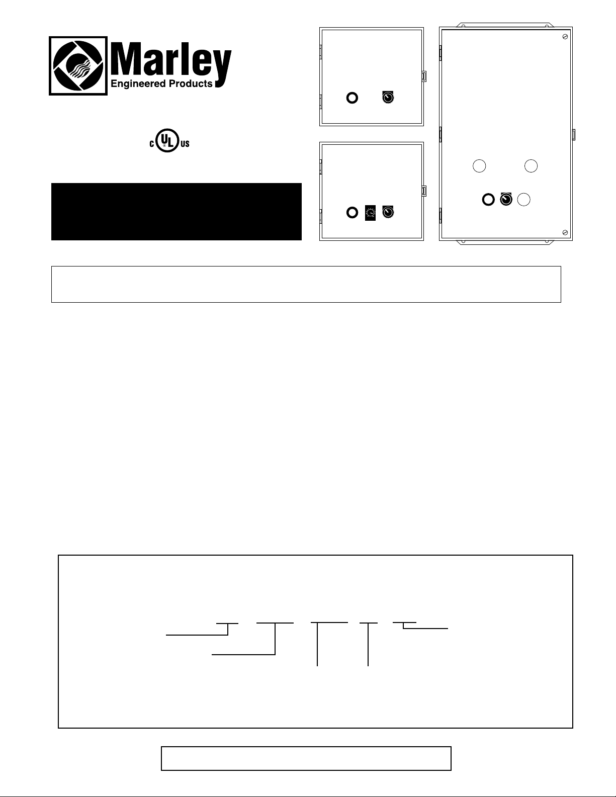
Power Control Panels
File #E166716
Installation & Operating Instructions
SAVE THESE INSTRUCTIONS
Description
The CP series Power Control Panels from Marley Engineered Products were developed to handle the additional requirements
needed when controlling quartz lamp, quartz tube, and metal sheath style infrared heaters. As a result, the additional features
included to support infrared heaters make this series of control panels an excellent solution for a variety of applications.
CP series Power Control Panels are factory wired for efficient installation, and include terminal blocks, On-Off selector switches, a power on Pilot light, and a 24 volt or 120 volt control circuit. Panels are available for use in 208, 240, 277, 480 and 600
volt systems, with amp loads up to 40, 50, 100, 200 and 300 amps.
Features
• NEMA 1 enclosure, UL Listed and Labeled Control Panel.
• On/Off Control Switch.
• Power On Pilot Light.
• Control terminals for remote One or Two Stage Controller, (two stage requires a minimum of two contactors).
• 600V Fuse Blocks,Type J, Max. 60 AMP for load splitting (fuses not supplied.)
• Heavy duty contactors, 50 amps full load , 65 amps resistive to 600 volts (except with Time Delay and Percentage
Timer Options).
• Control Transformer with fused primary and secondary, 24 or 120 volts.
• Percentage Timer Option for single contactor panel.
• Time Delay Controller (Intermittent Heat) for single contactor panel.
• Factory pre-wired for quick and easy installation.
*NOTE: These options are
available for 40 Amps max.
single contactor panels only
( ) = RESISTIVE RATING
Page 2
2
WARNING: To reduce the risk of electric shock, personal
injury, or fire, read and understand the following instructions
and adhere to the special safety precautions:
1. These control panels must be installed by qualified personnel only.
If in doubt, consult with a licensed electrician.
2. All installation and wiring must conform to the National Electrical
Code (NEC) and all other local codes and ordinances.
3. These panels are not suitable for installation into hazardous, corrosive, or wet atmospheres such as areas where flammable liquids, corrosive chemicals, etc. are used or stored or in areas
where subject to exposure to rain or water spray.
4. These panels must be securely mounted to an interior wall to the
building framing or structural members. Use care when cutting or
drilling into walls to avoid damage to hidden wiring or other utilities.
5. Refer to the wiring diagram provided on the interior control panel
door for special instructions for the particular panel you have.
6. All panels must be properly bonded to the building grounding system by connection to the grounding terminal in the panel.
7. All wiring brought into the panel must be rated 600 volt, 75
degrees C minimum.
8. A main disconnect or circuit breaker is required to allow for the
disconnecting of power to the control panel.
9. Make sure all electrical power to the panel is disconnected before
attempting to install or service the panel. Do not depend on a thermostat as the sole means for disconnecting the power. Always
disconnect power to control panel at main service panel and lock
power off so it cannot be accidentally turned on.
10.Always verify the electrical power coming to the control panel and
supplying loads matches the rating of the panel and the loads. A
mismatch could cause permanent damage to the equipment or a
possible fire.
WARNING
INSTALLATION
1. Inspect the control panel for hidden damage and confirm it is
the type and size needed for the installation.
Note: If control panel or any optional accessories are
found to have freight damage, contact carrier and
file claim with carrier. Do not return panel to factory for freight damage claims.
2. Determine the mounting location on interior wall and securely
mount panel to building structure using care to avoid damage
to hidden utilities.
3. Route conduit and power supply wiring to control panel from
main service panel.
4. Route conduit and supply power wiring from control panel to
loads(s).
5. Install any optional or remote control devices as required and
install wiring to control panel as required (see wiring diagram
on inside of control panel).
6. Determine branch circuit and load fusing in accordance with
the NEC (see also LOAD FUSING).
7. After installation, check for proper operation of all loads and
controls.
LOAD FUSING
Provide appropriate size and type of fuses for the type of load.
The fuse blocks provided in control panels with multiple contactors for load fusing are for type J, maximum 60 Amp, 600 Volt.
When using control panel to operate quartz lamp infrared heaters,
to allow for high starting current, branch circuit protection must be
of the TIME DELAYTYPE. For other types of infrared heat(quartz
tube and metal sheath), fast acting fuses are acceptable. (Refer
to the NEC).
The NEC requires a maximum branch circuit fusing for infrared
equipment of 50 Amps. The total connected infrared heating load
must not exceed 80% of the overcurrent device rating. Heaters
other than infrared types with supplemental fusing can be fused
up to 60 Amps for a total load of 48 Amps. The same is true for
motor loads or combination loads.
Circuits that need less than 35 Amp rated fuses will require the
use of reducers which will allow the use of 30 Amp and lower Amp
rated fuses to be mounted in 60 Amp rated fuse blocks. As an
option, increasing the wire size and thus the ampacity of the wires
used from the control panel to the load will allow the use of 35
Amp fuses as a minimum.
For the reasons noted above, and due to the many possible
installation combinations, load fusing is not provided with these
control panels. The user must determine the type and ratings for
the applicable fusing for the installation.
OPTIONAL CONTROLS AND ACCESSORIES:
REMOTE THERMOSTATS AND CONTROL DEVICES
The Marley Power Control Panels are provided with contactors to
switch the power to the heating load(s). the means of activating
these contactors may be by whatever means appropriated for the
application (either 24 or 120 volts - see wiring diagram in panel).
It is possible for a wall type thermostat to be used with infrared
heaters used indoors. However, care must be given to the location of the thermostat so it will operate properly. Avoid locating the
thermostat in direct exposure to the rays from infrared heaters. A
shield between the thermostat and the heaters may work well.
Thermostats are available in single and two stage. Two stage
models are generally considered to give more economical results
in many installations.
Marley Power Control Panels are provided with terminal blocks
that allow for the connection of remote thermostats or controllers.
Multi-contactor panels are provided with terminal blocks to allow
for connecting of a two stage thermostat. The contactors are
divided equally between the two stages.
PERCENTAGE TIMER
The single contactor control panel with a suffix PT in its Model
Number (i.e. CP404801PT) is provided with a percentage timing
control device. This is a continuing controller that turns ON and
OFF according to a preset time period. The time period for these
controllers is two minutes. Dial is set by choosing a percentage of
ON time. OFF time will then be the remainder of time on the two
minute cycle. EXAMPLE: Setting dial at 50% will activate the
heaters for one minute and deactivate for one minute for every
two minute cycle. 75% setting will activate the heater for one
minute and thirty seconds and deactivate for thirty seconds.
USAGE: This is used for spot heating especially in areas where
no warm air build up can be expected. The use of a remote
thermostat with this model panel will allow for total area heat
control. The setting of the thermostat and the dial setting on the
percentage timer can be coordinated to maintain a specific comfort level. The two minute cycling of the percentage timer will
only come ON during such times that the thermostat is calling
for heat. The Percentage Timer option is not for use with Quartz
Lamp Heaters.
!
Page 3

TIME DELAY CONTROLLER
The single contactor panel with a suffix CT in its Model Number
(i.e. CP404802CT) is provided with a time delay timer which
energizes a specific load in an area for intermittent periods of
time. It comes with a momentary push-button switch which activates the heating load for a preset cycle (adjustable between 1
and 30 minutes). The system is de-energized once the timer has
cycled. Once the cycle has started any push of the button will no
longer affect the timing. The cycle has to finish, the system has
to come off, and only then can the system restart for another
cycle with the push of the button. Since the option to connect a
remote controller is always available, the use of such a remote
controller will override the intermittent cycling of the system. The
system will come ON and OFF instantaneously with the remote
thermostat or controller. The system will stay energized for as
long as the remote controller keeps calling for heat. Only when
the remote thermostat is not calling for heat (R & W open) can
intermittent cycling start. Thus, if only intermittent heating is
desired, the panel will function without the need for a remote
controller. The terminal R and W in the panel must be kept open.
This is ideal for bus stops, loading docks, smoking areas or
remote work stations. Aremote controller would be used to
maintain a certain area from freezing and any temporary user of
the area would augment the heat requirement with a push of a
button. The timer has the facility to be able to adjust its time
period in the field. It is pre-set from the factory at the maximum
30 minute delay.
SINGLE PHASE APPLICATIONS
These control panels were primarily designed to handle three
phase loads. This is why the contactors and power supply terminal blocks provided with each panel have three poles. Except
for control panels with Time Delay and Percentage Timer options
contactors are rated and wired for 50 amps per pole. Where
fuses are required the fuse blocks provided have three poles
rated at 60 amps per pole. If the power supply is single phase
and the load is single phase, these panels can be used provided
the electrical loading on the wires and components are within
acceptable limits. The electrician must see to it that proper terminals are chosen (L1 & L2 for single phase) such that the primary
of the control transformer is energized . See typical wiring diagrams, Figures 1 and 3.
BALANCED THREE PHASE APPLICATIONS
Single phase infrared heaters can be wired to a three phase circuit under the following conditions. In applications where the
infrared heaters are single phase and the supply power is three
phase, the electrical load must be balanced across each of the
three phases. In order to accomplish this the heaters must be
used in combinations of three heaters equally rated. In this
installation, one heater would be wired to L1 and L2, the second
would be wired to L2 and L3, and the third wired to L3 and L1.
See typical wiring diagrams, Figures 2 and 4
TYPICAL WIRING DIAGRAMS
NOTE: Control wiring not shown for clarity. Refer to wiring diagrams with control panels.
Figure 2: Three phase supply- Three double element
heaters two stage control per heater.
Balanced three phase with two contactor panel.
Figure 1: Single phase supply- Three double element
heaters two stage control per heater with two
contactor panel
HTR 1 HTR 2
HTR 3
L1
L2
L1
L2
L1 L2
C1
C2
L1 L2 L3
L1
L2
C1
HTR 1 HTR 2
HTR 3
L3
L1
L2
L3
C2
Page 4

11/02
Part No. 5200-2627-000
PPD 024
HOW TO ORDER REPAIR PARTS
In order to obtain any needed repair or replacement
parts, warranty service or technical information, please
contact Marley Engineered Products Service Center tollfree by calling 1-800-642-HEAT.
When ordering repair parts, always give the information listed as follows:
1. The Part Number
2. The Model Number
3. The Part Description
4. Date of Manufacture
LIMITED WARRANTY
All products manufactured by Marley Engineered Products are warranted against defects in workmanship and materials for one year from date of installation, except heating elements which are warranted against defects in workmanship and materials for five years from date of installation. This warranty does not apply to damage from accident, misuse, or alteration; nor where the connected voltage is more than 5% above the nameplate voltage; nor to equipment improperly installed or wired or maintained in
violation of the product’s installation instructions. All claims for warranty work must be accompanied by proof of the date of installation.
The customer shall be responsible for all costs incurred in the removal or reinstallation of products, including labor costs, and shipping costs incurred to return products to
Marley Engineered Products Service Center. Within the limitations of this warranty, inoperative units should be returned to the nearest Marley authorized service center or
the Marley Engineered Products Service Center, and we will repair or replace, at our option, at no charge to you with return freight paid by Marley. It is agreed that such
repair or replacement is the exclusive remedy available from Marley Engineered Products.
THE ABOVE WARRANTIES ARE IN LIEU OF ALL OTHER WARRANTIES EXPRESSED OR IMPLIED, AND ALL IMPLIED WARRANTIES OF MERCHANTABILITY AND
FITNESS FOR APARTICULAR PURPOSE WHICH EXCEED THE AFORESAID EXPRESSED WARRANTIES ARE HEREBY DISCLAIMED AND EXCLUDED FROM THIS
AGREEMENT. MARLEY ENGINEERED PRODUCTS SHALL NOT BE LIABLE FOR CONSEQUENTIAL DAMAGES ARISING WITH RESPECT TO THE PRODUCT,
WHETHER BASED UPON NEGLIGENCE, TORT, STRICT LIABILITY, OR CONTRACT.
Some states do not allow the exclusion or limitation of incidental or consequential damages, so the above exclusion or limitation may not apply to you. This warranty gives
you specific legal rights, and you may also have other rights which vary from state to state.
For the address of your nearest authorized service center, contact Marley Engineered Products in Bennettsville, SC, at 1-800-642-4328. Merchandise returned to the factory must be accompanied by a return authorization and service identification tag, both available from Marley Engineered Products. When requesting return authorization,
include all catalog numbers shown on the products.
Figure 3: Single phase supply- Four double element heaters,
single stage control per heater with two contactor
panel (may be connected one or two stage)
Figure 4: Three phase supply- Six double element heaters, single stage
control per heater, balanced three phase with two contactor panel
(may be connected one or two stage)
L1
L2
L1 L2
C1
C2
HTR 1 HTR 2
HTR 3
L1
L2
HTR 4
L1
L2
L3
L1
L2
L3
L1 L2 L3
C1
C2
HTR 1 HTR 2
HTR 3
HTR 4 HTR 5
HTR 6
470 Beauty Spot Rd. East
Bennettsville, SC 29512 USA
 Loading...