

Page 1
Dear Owner,
Congratulations! Thank you for purchasing this new heater/fan manufactured by a division of Marley Engineered Products.
You have made a wise investment selecting the highest quality product in the heating industry. Please carefully read the
installation and maintenance instructions shown in this manual. You should enjoy years of efficient heating comfort with this
product from Marley Engineered Products... the industry’s leader in design, manufacturing, quality and service.
... The Employees of Marley Engineered Products
Read Carefully - These instructions are written to help you
prevent difficulties that might arise during installation of
heaters. Studying the instructions first may save you
considerable time and money later. Observe the following
procedures, and cut your installation time to a minimum.
CAUTION - TO REDUCE RISK OF FIRE, ELECTRICAL SHOCK
OR INJURY TO PERSONS,OBSERVE THE FOLLOWING:
1. Do not use this fan with any Solid-State speed control
device.
2. Use this unit only in the manner intended by the
manufacturer. If you have any questions, contact the
manufacturer.
3. Before servicing or cleaning unit, switch power off at
service panel and lock service panel to prevent power
from being switched on accidentally.
4. Installation work and electrical wiring must be done by
qualified person(s) in accordance with all applicable
codes and standards, including fire-rated construction.
5. Sufficient air is needed for proper combustion and
exhausting of gases through the flue (chimney) of fuel
burning equipment to prevent back drafting. Follow the
heating equipment manufacturer’s guideline and safety
standards such as those published by the National Fire
Protection Association (NFPA), and the American
Society for Heating Refrigeration and Air Conditioning
Engineers (ASHRAE), and the local code authorities.
6. When cutting or drilling into wall or ceiling, do not
damage electrical wiring or other hidden utilities.
7. Ducted fans must always be vented to the outdoors.
8. If this unit is installed over a tub or shower, it must be
marked as appropriate for the application. These units
are
NOT to be installed over a tub or in a shower stall
enclosure.
9. Do not install closer than 6” to any adjacent wall.
10. Do not install less than 6’ from floor.
11. Install R-40 reflector — type infrared heat lamp/lamps
375-watt maximum (not included).
12. NEVER place a switch where it can be reached from a
tub or shower.
13.
CAUTION: For General Ventilating Use Only!
Do not use to exhaust hazardous or explosive materials
and vapors.
14. Not for use in kitchens.
Installation & Maintenance Instructions
SA VE THESE INSTRUCTIONS
WARNING
!
Models A564&B674
Radiant Infrared Ceiling Heater
Models B560 & B660W
Radiant Infrared Heater/Fan
Combination
DESCRIPTION
The RADIANT INFRARED CEILING HEATERS AND HEATER/FAN COMBINATIONS listed in these instructions are intended
for use in restrooms, bathrooms and utility rooms. Any other applications are not approved. All models are U.L. Listed TYPE
I.C. (Thermally Protected) for use in insulated ceilings.
IMPORTANT: DO NOT INSTALL OVER ATUB OR SHOWER STALL ENCLOSURE.
UNPACKING
Unpack carefully. If there are missing components or hidden damage, immediately contact your distributor or the delivering
carrier concerning discrepancies.
TOOLS
Installation of your Marley Engineered Products heater is easy . No special technical knowledge is needed; only a few ordinary tools are
required.
Screwdriver Wire stripper
Hammer Wire nuts and general electrical supplies
Saber saw, Keyhole saw, or Jig saw Safety glasses
Electric drill with bit Ruler and straight edge
Wire cutters
All hand tools should be insulated. Power tools should display the UL Listing Mark.
Page 2
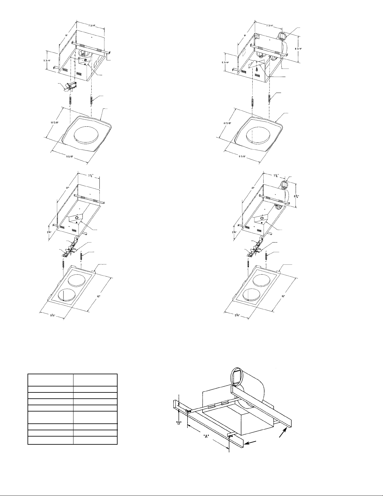
MODEL A564
MODEL B560
MODEL B674W
MODEL B660W
MOUNTING BRACKETS
OUTLET BOX COVER
GRILLE MOUNTING
SPRINGS
GRILLE
COOLING FAN
OUTLET BOX
GRILLE MOUNTING
SPRINGS
GRILLE
COOLING FAN
OUTLET BOX COVER
GRILLE MOUNTING
SPRINGS
GRILLE
LAMP-
HOLDER
LAMPHOLDER
AIR DISCHARGE
OUTLET
OUTLET BOX
GRILLE MOUNTING
SPRINGS
GRILLE
COOLING FAN
LAMP-
HOLDER
LAMPHOLDER
FIG. 1
2
MOUNTING BRACKETS
AIR DISCHARGE
OUTLET
NEW HOME INSTALLA TION
1. Insert 4 mounting brackets with angles pointing away from housing. In approximate location between joists where housing will be
located, drive 2 nails (see dimensions “A” and “B” in Fig. 2) leaving 1/4” of nail projecting. Position one set of brackets over nails and
drop in to place. Extend the remaining mounting brackets to the adjacent joist and repeat nailing procedure. Finish driving nails and
adjust housing between ceiling joists.
Note:The housing can not be adjusted closer than 4”to the side of either joist on 24” O.C. construction.
FIG. 2
MODEL DIMENSION
NUMBER “A”
A564 11 1/4”
B560 11 1/4”
B660W 15 3/8”
B674W 15 3/8”
CEILING DIMENSION
THICKNESS “B”
3/8” 1 1/8”
1/2” 1”
3/4” 7/8”
NOTE: BRACKETS MUST BE NAILED FROM
ABOVE IF CEILING IS IN PLACE.
Ceiling Joist
Page 3

2. Remove outlet cover. Run 120VAC, 60Hz power cables from wall switch/switches to appropriate knockout in housing. Remove
knockout and install BX or Romex connector in outlet box. (Refer to Fig. 3 for the wiring diagram designated for the model being
installed.) Feed cables through the box connector and make connections in outlet box using approved connectors. Connect ground
wire to green ground screw.
CAUTION:Do not disconnect or separate any factory installed connections. Cooling fan must be on when lamp/lamps are on.
BE SURE ALL WIRING COMPLIES WITH LOCAL AND NATIONAL ELECTRICAL CODES
AND THE UNIT IS PROPERLY GROUNDED
a
CAUTION
!
FIG. 3
OUTLET BOX
LAMP
RED
BLACK
WHITE
WHITE
BLACK
WHITE
GROUND
WHITE
BLACK
THERMAL
PROTECTOR
GROUND
SCREW
WALL
SWITCH
120V 60 HZ
POWER SUPPLY
MODEL A564 WIRING DIAGRAM
COOLING FAN
(DO NOT
SEPARATE LEADS)
OUTLET BOX
LAMP
RED
BLACK
WHITE
WHITE
BLACK
WHITE
GROUND
WHITE
BLACK
THERMAL
PROTECTOR
GROUND
SCREW
VENTILATOR
AND LAMP
WALL SWITCH
120V 60 HZ
POWER SUPPLY
MODEL B560 WIRING DIAGRAM
(DO NOT
SEPARATE LEADS)
VENTILATOR MUST BE
ON WHEN LIGHT IS ON.
VENTILATOR
MOTOR
OUTLET BOX
FIRST LAMP
BLACK
BLACK
BLACK
WHITE
WHITE
BLACK
WHITE
GROUND
WHITE
BLACK
THERMAL
PROTECTOR
GROUND
SCREW
120V 60 HZ
POWER SUPPLY
MODEL B660W WIRING DIAGRAM
VENTILATOR
MOTOR
SECOND LAMP
COOLING FAN
(DO NOT
SEPARATE LEADS)
RED
BLUE
WHITE
OUTLET BOX
FIRST LAMP
BLACK
BLACK
WHITE
WHITE
BLACK
WHITE
GROUND
WHITE
THERMAL
PROTECTOR
GROUND
SCREW
120V 60 HZ
POWER SUPPLY
MODEL B674W WIRING DIAGRAM
SECOND LAMP
COOLING FAN
(DO NOT
SEPARATE LEADS)
RED
BLUE
LAMPS
WALL
SWITCH
VENTILATOR
WALL
SWITCH
WALL
SWITCH
3
(Ventilator Models Only)
3. Run four inch round duct from ventilator air discharge outlet to wall cap or roof cap. (See Fig. 4)
Important: Be sure nothing obstructs the discharge of the ventilator . Take precautions to insure that insulation does not get into duct
work or air discharge opening.
4. Install grille by hooking one end of the two springs provided in the holes in either end of the housing. Hook the other ends of the
springs in the small holes in the grille. (See Fig. 5).
5. Install R-40 reflector-type infrared heat lamp/lamps 375 watt maximum (not included).
6. Insure the grille opening/openings are centered around the lamp/lamps. The lamps may not give satisfactory performance if in
contact with the grille.
RISK OF FIRE!
USE OF LAMPS OTHER THAN THOSE SPECIFIED CONSTITUTES A FIRE HAZARD
a
WARNING
!
RISK OF FIRE!
NEVER PLACE ANYTHING IN FRONT OF LAMPS OR BLOCK UNIT IN ANY MANNER.
a
WARNING
!
Page 4

THERMAL PROTECTION
This unit is Thermally Protected. If the cooling fan stalls or the unit is not field wired in accordance with the wiring
Diagrams (Fig. 3), the heat generated by the lamps will cause the protector to cut the unit off. After the unit has cooled off, the protector will
switch the unit back on, allowing the lamps to become energized. The unit will again heat up and cut off. This cycle will be repeated over and
over unless steps are taken to correct the problem. THIS CONDITION SHOULD NEVER BE ALLOWED TO CONTINUE. If necessary, the
unit should be serviced by an authorized representative.
In addition, the ventilator motor has an internal thermal protector in case the ventilator does not start when the ventilator switch is turned on.
This condition should be investigated. NEVER LEAVE SWITCH IN “ON” POSITION WHEN VENTILATOR DOES NOT START! Always
disconnect unit from power source before servicing it.
FIG. 4
FIG. 5
ROOF CAP
WALL CAP
4” DIA. DUCT
TYPICAL DUCTING
INSTALLATION
HORIZONTAL
AND HORIZONTAL
TO VERTICAL
DISCHARGE
SPRING
MOUNT
INSTALLATION IN EXISTING HOMES
1. Carefully read all previous installation instructions and
follow those applicable to your installation, including
ducting and wiring. (See Figs. 3, 4, & 5)
2. Drill a small hole in the ceiling from below in proposed
location, then locate this hole in the attic.
3. In attic, mark ceiling for cutout by using housing as
template.
Note:The housing can not be adjusted
closer than 4”to the side of either joist on 24”O.C.
construction. Using this line make a cutout about
1/4” larger.
4. Place housing with mounting brackets installed into
hole and rest mounting brackets on sheetrock. Adjust
housing so that it will be flush with the finished ceiling.
(See dimension “A” in Fig. 2). Extend and nail all four
ends of mounting brackets.
5. Perform steps 2 through 6 as for new construction.
SPECIFICATIONS:
MODEL VOLTS MAXIMUM BTHU DUCT CFM H.V.I. CERTIFICATION (SQ. FT.)
WATTS SIZE RATING BATH KITCHEN OTHER
A564 120 375 1280 N/A N/A N/A N/A N/A
B560 120 375 1280 4” 70 65 N/A 85
B660W 120 750 2560 4” 70 65 N/A 85
B674W 120 750 2560 N/A N/A N/A N/A N/A
LIMITED WARRANTY
Dear Customer,
Thank you for your interest in Marley Engineered Products. We’re sure you will enjoy its
benefits for many years to come. Please take a minute to fill out the following information
and keep it in your permanent records.
Date Purchased Date Installed
Model Number Serial Number
LIMITED WARRANTY
This Marley Engineered Products heater is warranted to be free of defects in material and
workmanship for 12 months from date of original purchase.
There is no other warranty, express or implied, except such as is expressly set forth herein.
Seller will not be liable for any general, consequential, or incidental damages, including without
limitation any damages for loss of use or loss of profits, for any breach of warranty or for
negligence. Seller’s liability and buyer’s exclusive remedy are limited to the repair of defective
goods or the shipment of equivalent goods, or the granting of a reasonable allowance on
account of any defects, as the seller may elect.
To obtain performance under this warranty, you must:
1. Contact the Marley Engineered Products Service Department at 1-800-642-HEAT
between the hours of 8:00 a.m. and 5:00 p.m. E.S.T. Monday through Friday.
2. Provide the model number of the product, the date of installation, and state the nature of
the difficulty being experienced.
Products within warranty which have been installed and returned to the seller for repair will
be repaired and returned as used products. Repairs to products outside the warranty period
will be subject to labor and parts charges.
Some states have enacted legislation which (a) does not allow the inclusion of limitations
on incidental or consequential damages; (b) does not allow limitations on the length of a
warranty period; (c) precludes exclusion, during the period of a limited warranty, of any
implied warranties of merchantability or fitness for purpose.
To the extent of such provisions being applicable in your state, the limitations in this
warranty may not apply.
TO ENSURE SAFE OPERATION
• Be sure that this unit is correctly installed and wired by a qualified installer in accordance
with the instructions and applicable NEC or equivalent codes.
• Be sure that operating instructions are followed and that moving and heating parts are
kept clean and free from obstructions.
Any warranties granted or liabilities assumed hereunder will not apply to goods that have
been damaged in transit, altered, repaired, installed or operated otherwise than in
conformity with the above requirements for safe operation.
3. The Marley Engineered Products Service Representative will determine the best way
to resolve the difficulty.
HOW TO ORDER REPAIR PARTS
In order to obtain any needed repair or replacement parts, warranty service or
technical information, please contact Marley Engineered Products Service Center
toll-free by calling 1-800-642-HEAT.
When ordering repair parts, always give the information listed as follows:
1. The Part Number
2. The Model Number
3. The Part Description
4. Date of Manufacture
Part No. 5200-2517-001 ECR 34491
9/01
470 Beauty Spot Rd. East
Bennettsville, SC 29512 USA
 Loading...