

Page 1
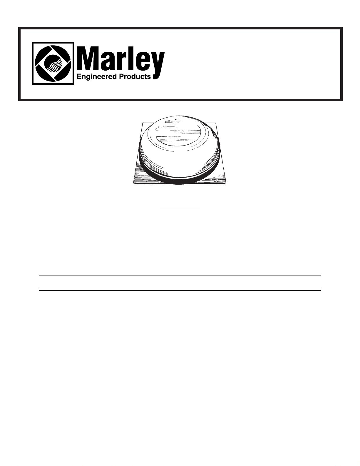
MODEL ASRV 14
POWER ATTIC
SPACE VENTILATOR
READ AND SAVE THESE INSTRUCTIONS.
ATTENTION
This ventilator’s flashing plate may possibly have been distorted during shipping and handling. Any
such distortion does not represent defective product and is not returnable for that reason. Flashing
material is purposely designed to be soft and flexible in order to allow the flashing plate to conform to the contour of the roof.
IMPORTANT SAFETY INSTRUCTIONS
WARNING:
TO REDUCE THE RISK OF FIRE, ELECTRICAL SHOCK
OR INJURY TO PERSONS, OBSERVE THE FOLLOWING:
1. Do not use this fan with any Solid-State Speed Control Device.
2. Use this unit only in the manner intended by the manufacturer. If you have questions, contact the manufacturer.
3. Before servicing or cleaning unit, switch power off at service panel and lock service panel to prevent power from
being switched on accidentally.
4. Installation work and electrical wiring must be done by qualified person(s) in accordance with all applicable codes
and standards, including fire-rated construction.
5. Sufficient air is needed for proper combustion and exhausting of gases through the flue (chimney) of fuel burning
equipment to prevent back drafting. Follow the heating equipment manufacturer’s guideline and safety standards
such as those published by the National Fire Protection Association (NFPA), and the American Society for
Heating Refrigeration and Air Conditioning Engineers (ASHRAE), and the local code authorities.
6. “When cutting or drilling into wall or ceiling, Do Not damage electrical wiring or other hidden utilities.
7. CAUTION: This unit has an unguarded impeller. Do not use in locations readily accessible to people or animals.
8. CAUTION: For general ventilation use only! Do not use to exhaust hazardous or explosive materials and vapors.
Page 2
GENERAL INFORMA TION
1. For a power attic ventilator to effectively cool, it should provide at least ten air changes per hour. To
determine the proper CFM rating for a fan that will provide that number of air changes, the total square
footage of an attic must be multiplied by .7. This will give the CFM rating for the fan needed for an attic.
Example: for a home with 1500 square feet of attic space, the calculation would be as follows:
1500 x .7 = 1050. A fan with 1050 CFM rating would be needed for such an attic. For dark roofs, 15%
should be added to this CFM calculation. If a roof is particularly steep, a slightly higher CFM rating
should be sought.
2. The air intake area must be adequate for proper operation of the power attic ventilator. One square
foot of free open air inlet per 300 CFM of fan capacity is recommended. See “Attic Intake Area
Required” section.
3. Along with the power attic ventilator’s summer advantages, it also offers home protection during the
winter. In winter months, moist air creeps into the attic from the house below, condensing on the
underside of the roof boards, beams and other materials. Excessive moisture can rapidly deteriorate
these materials. It can also penetrate insulation, reducing its effectiveness and making the home less
energy efficient. An accessory dehumidistat can be used with this power attic ventilator to automatically activate unit in the winter to combat excessive moisture.
4. The power attic ventilator is designed for ventilating attic space. Do not use unit to exhaust dirt, dust,
grease or lint laden air.
INST ALLATION
NOTE: For maximum operating efficiency, the proper intake air opening must be provided to allow replacement of exhaust air. See “Attic Intake Area Required” section.
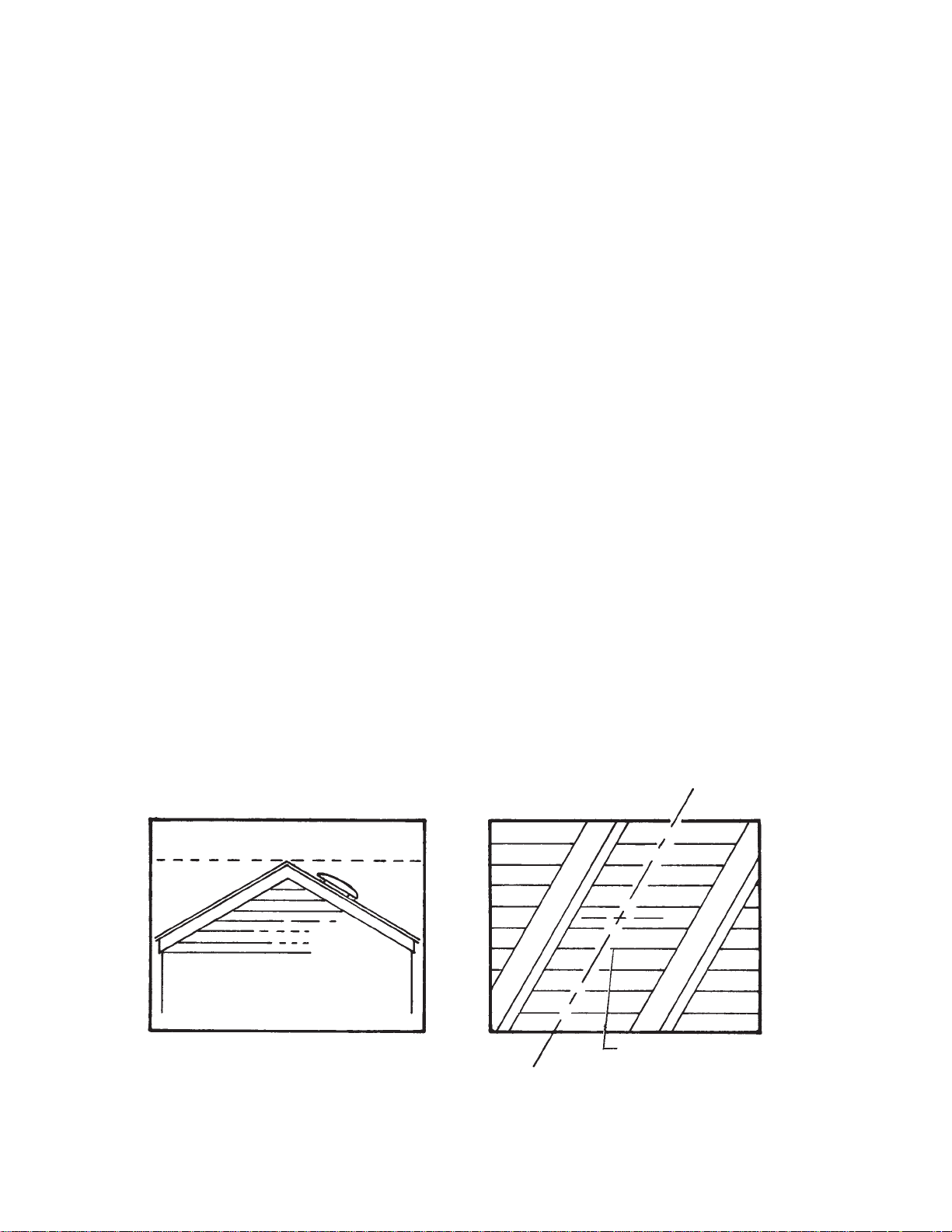
1. The unit should be installed as close to the center of the roof ridgeline as possible on the rear slope
of the roof. The uppermost portion of ventilator dome should be just below ridge level. See Fig. 1.
2. After locating unit in desired installation position on top of roof, measure from the unit to the ends of
the roof and to the ridgeline. Using these measurements, locate the spot inside the attic directly under
the spot on the roof where the unit has been placed. Locate a centerline position between two rafters
as close as possible to this established position and drill a pilot hole through the roof from the inside.
See Fig. 2.
2
FIG. 1 FIG. 2
Front
C
Drill Hole
L
Rafter
Rafter
Page 3
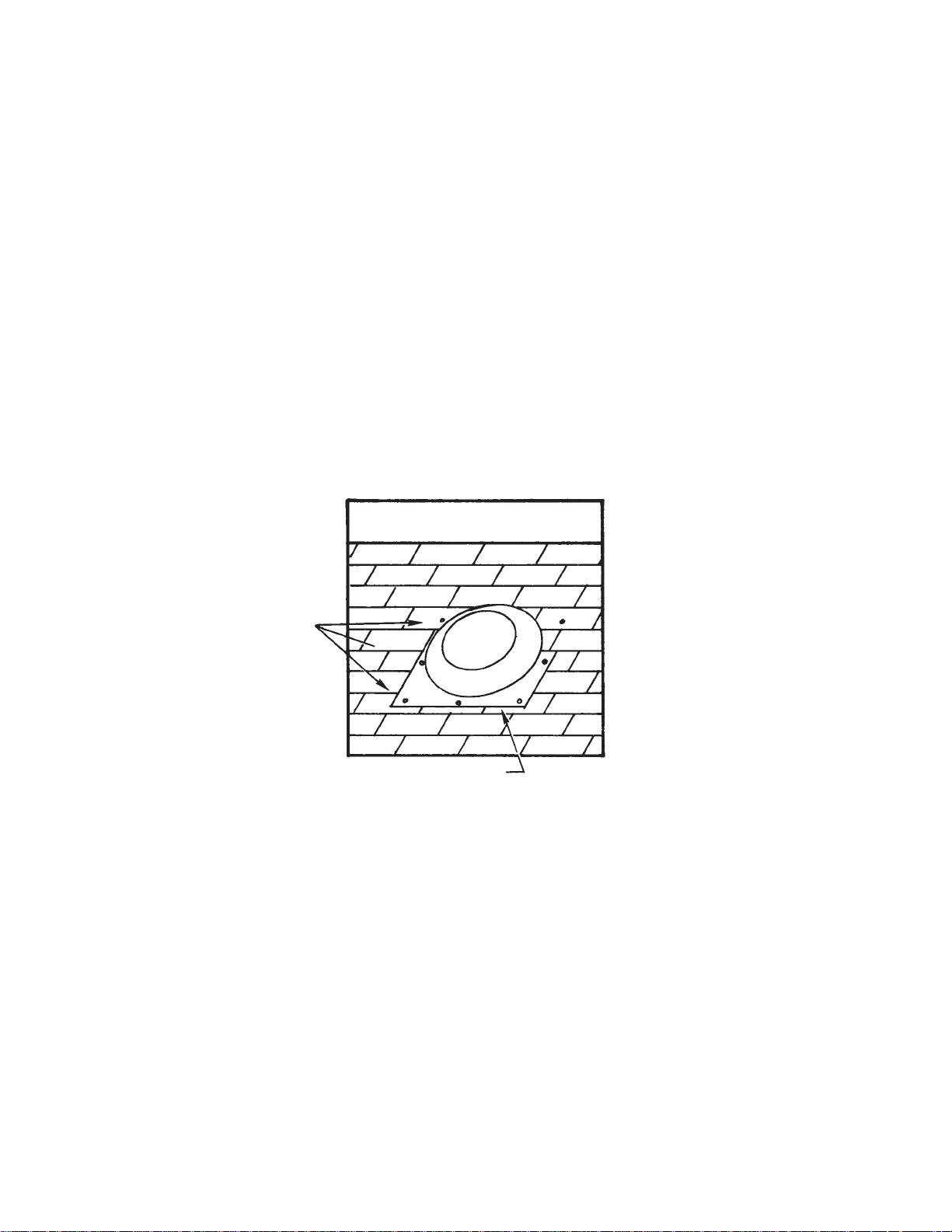
3. Cut a rectangular hole centered around the drilled hole 14 1/2” wide by 17” long. Be sure the 17” side
is parallel to the rafters.
4. With mounting plate parallel to ridgeline of roof, slide the upper outer flange of the plate under the row
of shingles just above the cutout so that the housing portion of unit can be centered in the cutout
opening. See Fig. 3.
5. Caulking or roofing cement must be used to seal the mounting plate to the roof, especially bottom and
side areas of flange not covered by shingles.
6. With unit in place, nail the top left corner and top right corner of flange to roof decking and rafters with
galvanized roof nails. This is accomplished by nailing directly through the aluminum plate. Nail the bottom of the flange the same way. Check to be sure all shingles are securely and neatly in place over
top portion of flange. See Fig. 3. Caulking nail heads is recommended.
7. Installation should be water checked by using a garden hose and spraying water directly on top of
unit. Do not spray water directly into vent opening.
FIG. 3
Ridgeline
Apply Caulking
Nails
3
Page 4

MINIMUM A TTIC INT AKE AREA REQUIRED
Sufficient intake area must be provided in the attic to assure that the fan will not be overloaded and that
it will deliver its rated CFM. This can be accomplished with some type of attic venting such as gable
louvers or under-eave vents. The table below shows the minimum intake area needed for each fan
installed.
MINIMUM ATTIC INTAKE AREA REQUIRED
(All Areas Are In Square Feet)
UNRESTRICTED* WOOD LOUVER* METAL LOUVER*
OPENING REQD. OPENING REQD. OPENING REQD.
3.0 4.0 3.4
*If openings are covered with 1/2” hardware cloth or large mesh expanded metal increase area by 20%.
Double area if fly screen is used.
SPECIFICATIONS
FAN MOTOR @ 120VAC 60 HZ
SIZE RPM HP AMPS WATTS
14” 1550 1/35 2.2 200
* HVI Certified at 0.03” Static Pressure
DIMENSIONS
FIG. 4
61⁄2”
2”
14
1
⁄2” DIA.
26”DIA.
23” SQUARE
3” HIGH VENTURI
4
Page 5

TO MOTOR
WHITE
WHITE
BLACK
GROUND
THERMOSTAT
TO MOTOR
WHITE
WHITE
BLACK
GROUND
THERMOSTAT
DEHUMIDISTAT
JUNCTION
BOX
FIG. 5 FIG. 6
WIRING INSTALLATION
WARNING: To reduce the risk of fire or electrical shock, do not use this fan with any solid state speed
control device.
(This fan is designed to run on 120 volts, 60 Hz power only)
1. Wiring of this unit is done inside of the attic. Remove cover from thermostat/junction box. Bring the
power cable at least 6” into the box. Fasten power cable to box with appropriate connector.
120 VOLT
SUPPLY
120 VOLT
SUPPLY
2. For standard installation, connect the two leads in the thermostat/junction box to the two supply leads.
Attach ground wire from the supply to the green ground screw in the box. See Fig. 5.
3. See Figure 6 for wiring dehumidstat to ventilator.
4. Replace cover to thermostat/junction box.
5. The ventilator will automatically turn “ON” when the attic temperature rises above 105 ºF and will turn
“OFF” when the temperature drops below 95ºF.
5
Page 6

WARNING: The motor is thermally protected and automatically temperature controlled and may start
without warning; therefore, make certain that the power source is disconnected before
attempting to service or disassemble any components! If the power disconnect is out of
sight, lock it in the open position and tag to prevent application of power.
TROUBLE SHOOTING CHART
WARNING: Items marked with an asterisk (*), should be performed only by experienced and qualified
personnel.
SYMPTOM POSSIBLE CAUSES CORRECTIVE ACTION
Excessive noise 1. Propeller blade contacting housing *1. Realign or replace
2. Foreign material inside housing *2. Clean
3. Motor loose *3. Secure properly
4. Motor needs oiling *4. See lubrication
5. Dirt accumulation on propeller, *5. Clean
causing imbalance
Insufficient air flow 1. Not enough eave vents to provide *1. See Installation
“make-up” air
2. Clogged screen . *2. Clean or replace
Unit fails to operate 1. Blown fuse or open circuit breaker *1. Replace fuse or reset circuit
breaker
2. Motor *2. Replace
3. Thermostat *3. Replace
6
LUBRICATION: To prolong the life of the motor, oil motor every six months of use with S.A.E. 20
Motor Oil.
Page 7

7
REF
NO DESCRIPTION QTY.
11* DOME COVER 1
12* SCREW, 10-12 X 3/8 TYPE AB HEX HEAD 3
13* FAN BLADE ASSEMBLY 1
14* MOTOR, SHADED POLE 120V 1/35 HP 1
15* SCREEN 1
16* NUT, SERRATED FLANGED 1/4-20 3
17* BRACKET, DOME 3
18* GROMMET 3
19* SCREW, 1/4-20 X 1 3
10* VENTURI PLATE 1
11* MOTOR MOUNT ASSEMBLY 1
12* SCREW, 1/4-20 X 1 1/4 1
13* NUT, SPEED 1/4-20 1
14* THERMOSTAT & JUNCTION BOX 1
15* WASHER, #10 CUP 1
16* SCREW, 10-32 X 3/8 TYPE “F” 2
17* THERMOSTAT, FIXED (ON 105 F - OFF 95 F) 1
18* SCREW, 6-18 X 1/4 TYPE “B” 2
19* COVER, THERMOSTAT & JUNCTION BOX 1
20* SCREW, 8-32 X 3/8 TYPE “F” 1
21† INSTRUCTION BOOK 1
* STANDARD HARDWARE ITEM, AVAILABLE LOCALLY
† ITEM NOT SHOWN
Page 8

Part No. 5200-2547-000 PPD 035
3-00
LIMITED W ARRANTY
Dear Customer,
Thank you for your interest in Marley Engineered Products products. We’re sure you will
enjoy its benefits for many years to come. Please take a minute to fill out the following
information and keep it in your permanent records.
Date Purchased Date Installed
Model Number Serial Number
LIMITED WARRANTY
This Marley Engineered Products product is warranted to be free of defects in material and
workmanship for 12 months from date of original purchase.
There is no other warranty, express or implied, except such as is expressly set forth herein.
Seller will not be liable for any general, consequential, or incidental damages, including without
limitation any damages for loss of use or loss of profits, for any breach of warranty or for negligence. Seller’s liability and buyer’s exclusive remedy are limited to the repair of defective
goods or the shipment of equivalent goods, or the granting of a reasonable allowance on
account of any defects, as the seller may elect.
To obtain performance under this warranty, you must:
1. Contact the Marley Engineered Products Service Department at 1-800-683-0062 between
the hours of 8:00 a.m. and 5:00 p.m. E.S.T. Monday through Friday.
2. Provide the model number of the product, the date of installation, and state the nature of
the difficulty being experienced.
Products within warranty which have been installed and returned to the seller for repair will
be repaired and returned as used products. Repairs to products outside the warranty period will be subject to labor and parts charges.
Some states have enacted legislation which (a) does not allow the inclusion of limitations
on incidental or consequential damages; (b) does not allow limitations on the length of a
warranty period; (c) precludes exclusion, during the period of a limited warranty, of any
implied warranties of merchantability or fitness for purpose.
To the extent of such provisions being applicable in your state, the limitations in this warranty may not apply.
TO ENSURE SAFE OPERATION
• Be sure that this unit is correctly installed and wired by a qualified installer in accordance
with the instructions and applicable NEC or equivalent codes.
• Be sure that operating instructions are followed and that moving and heating parts are
kept clean and free from obstructions.
Any warranties granted or liabilities assumed hereunder will not apply to goods that have
been damaged in transit, altered, repaired, installed or operated otherwise than in conformity with the above requirements for safe operation.
3. The Marley Engineered Products Service Representative will determine the best way
to resolve the difficulty.
HOW TO ORDER REPAIR PARTS
In order to obtain any needed repair or replacement
parts, warranty service or technical information, please
contact Marley Engineered Products Service Center tollfree by calling 1-800-642-HEAT.
When ordering repair parts, always give the information listed as follows:
1. The Part Number
2. The Model Number
3. The Part Description
4. Date of Manufacture
470 Beauty Spot Rd. East
Bennettsville, SC 29512 USA
 Loading...