

Page 1
READ AND SAVE THESE INSTRUCTIONS.
MODEL A20DD
WHOLE HOUSE VENTILATOR
FOR 24” O.C. TRUSS CONSTRUCTION
IMPORTANT SAFETY INSTRUCTIONS
WARNING:
TO REDUCE THE RISK OF FIRE, ELECTRICAL SHOCK
OR INJURY TO PERSONS, OBSERVE THE FOLLOWING:
1. Do not use this fan with any Solid-State Speed Control Device.
2. Use this unit only in the manner intended by the manufacturer. If you have questions, contact the manufacturer.
3. Before servicing or cleaning unit, switch power off at service panel and lock service panel to prevent power from being switched on accidentally.
4. Installation work and electrical wiring must be done by qualified person(s) in accordance with all applicable codes and standards, including firerated construction.
5. Sufficient air is needed for proper combustion and exhausting of gases through the flue (chimney) of fuel burning equipment to prevent back
drafting. Follow the heating equipment manufacturerʼs guideline and safety standards such as those published by the National Fire Protection
Association (NFPA), and the American Society for Heating Refrigeration and Air Conditioning Engineers (ASHRAE), and the local code authorities.
6. CAUTION: For general ventilation use only! Do not use to exhaust hazardous or explosive materials and vapors.
7. When cutting or drilling into wall or ceiling, Do Not damage electrical wiring or other hidden utilities.
8. CAUTION: This unit has an unguarded impeller. Do not use in locations readily accessible to people or animals.
INTRODUCTION
Your Whole House Ventilator is designed and engineered to provide years of satisfactory service in cooling and ventilating your entire house. Hot,
humid air is drawn from the living areas and replaced by cooler outside air. This cooler air may be routed through selected areas of the house by opening the proper windows and doors. This Whole House Ventilator is a direct drive unit to provide maximum ventilation at minimum sound levels. It is
pull-chain operated from the living area. It is specifically designed and engineered to eliminate cutting of ceiling joists or truss members, thus providing
the easiest installation available.
MODEL CEILING OPENING REQUIRED FOR SHUTTER CLEAR SPACE REQUIRED
A20 DD 22” X 26” 24” X 28”
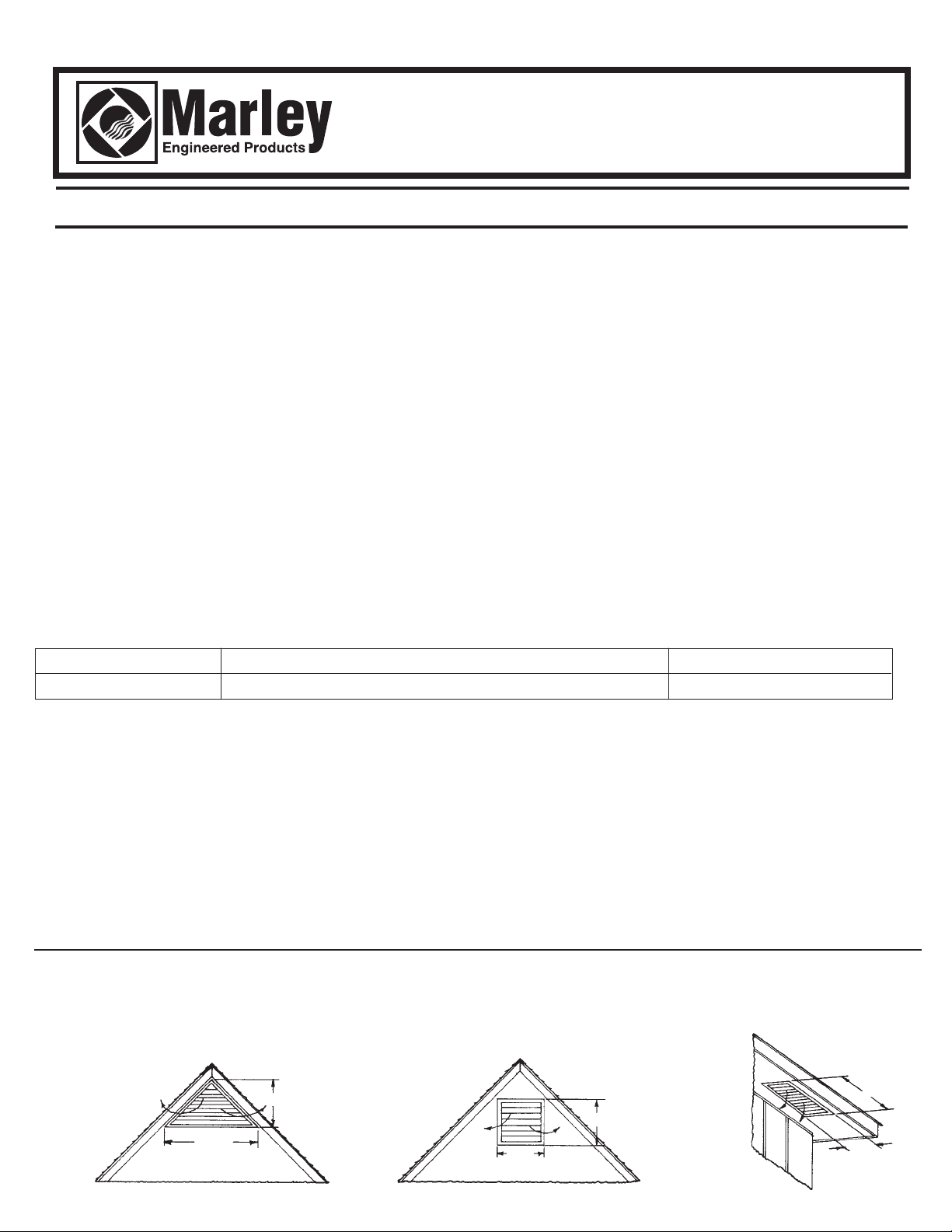
ATTIC AIR INTAKE AND DISCHARGE
Your Whole House Ventilator will be discharging a large volume of air into the attic every minute. Provisions must be made to allow this air to
escape to the outside. The sketches below (Figure 1) illustrate several different types of exhaust vents that are in common usage. Of these
types, the under-eave and gable methods are the most prevalent. Under-eave is probably the most satisfactory from the standpoint of simplicity and economical installation. Make sure under-eave vents are not blocked with ceiling insulation. The fan requires a given amount of
exhaust outlet in order to ensure quiet operation and unrestricted air movement. The table below shows the minimum area required for proper operation of fan. Sufficient ventilation is very important. Unless enough is provided, the fan motor will run hot, activating the thermal protector and shutting off the motor. When it cools, it will restart. Such intermittent operation is usually an indication of too little outlet air or too
little intake air through the house.
MINIMUM ATTIC DISCHARGE AREAS REQUIRED
(All areas are in square feet)
FAN UNRESTRICTED* WOOD LOUVRE* METAL LOUVRE* SHUTTERS
SIZE OPENING REQD. OPENING REQD. OPENING REQD. AUTO. MAN. ETC.
20” 5.0 11.25 8.75 3.1
*If fly screen is used, double these values. If 1/2” hardware cloth or large mesh expanded metal are used, the values given are sufficiently large. If no
screen used, reduce values shown by 20%.
FIG. 1
(1/2 A X B = AREA Sq. Ft.)
GABLE EXHAUST
B (Ft.)
A (Ft.)
(A X B = AREA Sq. Ft.)
GABLE EXHAUST
A
(Ft.)
B (Ft.)
(A X B = AREA Sq. Ft.)
EAVE
EXHAUST
B (Ft.)
A
(Ft.)
Page 2
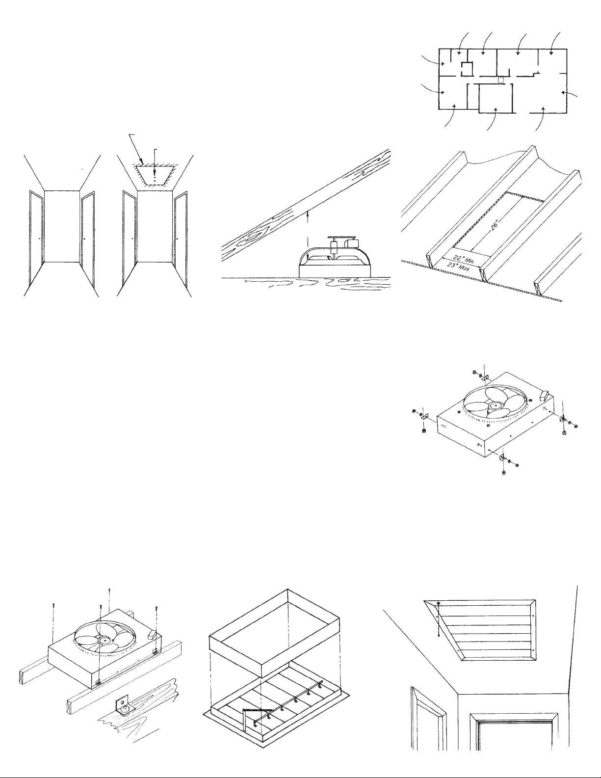
Step 1.
Fan should be located in center of house, preferably in hallway or corridor. This will allow air to
be drawn through all parts of living space. (See Fig. 2.)
Step 2.
Determine truss direction and locate one truss (joist). Lightly pencil a rectangular opening 22” x
26” on ceiling (with 26” side parallel to truss direction ) where shutter is to be located. Check to be
sure at least 2 inches of clearance area is available for overlap of shutter flanges. (See Fig. 3 and
Fig. 4.) Drill a small pilot hole in the center of this rectangle in the ceiling.
OVERLAP AREA
PILOT HOLE
FIG. 5A
ROOF RAFTERS
18” MIN
CLEARANCE
FIG. 2
FIG. 5B
FIG. 3 FIG. 4
Step 3.
Now, clear insulation and find pilot hole in attic, and tentatively lay out same rectangular hole as on ceiling below. Adjust location of this hole
so as to insure a vertical clearance from rafters of 18” above joists. There must be a minimum of 22” between joists and a maximum of 23”.
(See Figs. 5A and 5B.)
Step 4.
Carefully cut hole in ceiling flush with joists.
FIG. 6
Step 5.
Install angle brackets on each side of fan using hardware provided. Position brackets as shown
in (Fig. 6). Use outermost holes on side of fan.
to center of fan. (See Fig. 6.)
Step 6.
Position fan over opening. Screw fan mounting brackets to joists using rubber grommets and
wood screws provided. (See Fig. 7.) Attach extra length of chain to control switch.
Step 7.
Lift spring holder into position as shown below. Lock to edge of frame by turning screw inward. Spring may now be hooked to connector.
Adjust spring tension with shutter lying flat on floor by moving the hook from one hole to another hole in the connector UNTIL THE BLADES
OF THE SHUTTER JUST CLOSE.This adjustment is important.
Step 8.
Slide sleeve over shutter as shown in Fig. 8. Position shutter and sleeve in ceiling with chain hole aligned with control switch. Sleeve should
fit inside fan housing. Make sure shutter is aligned directly beneath fan and that it opens and closes freely. Secure shutter to ceiling. Pass
chain through hole in shutter so that it hangs freely in hallway. (See Fig. 9.)
FIG. 7
If either of these is blocked, use next hole closest
FIG. 8
FIG. 9
SLEEVE
— 2 —
SHUTTER
Page 3

Step 9.
Connect wiring as shown below (Fig. 10, 11).
Step 10.
Fan is a 3-speed fan controlled by a 4-position switch as follows: OFF - HI - MED - LOW - OFF. Select speed as required by pulling the chain
in the hallway. Shutter opens and closes automatically as fan is turned on or off. Shutter will open on any fan speed; however, at low speed,
complete opening could take up to one minute. We suggest you run the fan at high speed for 30 - 45 seconds to insure the shutter is completely open before switching to a lower speed.
FIG. 10
CAPACITOR
FIG. 11
ALL WIRING TO MEET LOCAL BUILDING CODES AND NATIONAL ELECTRICAL CODE STANDARDS.
CAPACITOR
— 3 —
Page 4

REF
NO. DESCRIPTION QTY.
REF
NO. DESCRIPTION QTY.
1 RETAINING RING 1
2 FAN BLADE ASSEMBLY 1
3 MOTOR, PSC 120V 1/5 HP 3-SPEED 1
4* SCREW, 8-18 X 1/4 TYPE “AB” 8
5 SPACER 4
6 GROMMET 4
7* SCREW, 10-16 X 1/2 TYPE “AB” 4
8 MOUNTING BRACKET 4
9 RING GROMMET 8
10* SCREW, 10-16 X 1/2 TYPE “B” 2
11 CAPACITOR MOUNTING BRACKET 1
12 CAPACITOR 5MFD 370V 1
13 BOOT, CAPACITOR TERMINAL COVER 1
14 FAN HOUSING ASSEMBLY 1
15* KEPS NUT 8-32 2
16* LOCK WASHER, INTERNAL TOOTH 3/16” ID 1
17* SCREW, 10-32 X 1/2 TYPE “F” 1
18 BX CONNECTOR 1
19 ANTI-SHORT BUSHING 2
20 FLEXIBLE CONDUIT 1
21 SLEEVE ASSEMBLY 1
22 FOAM GASKET STRIP 8 LF
23 SWITCH & JUNCTION BOX 1
24* GROUND SCREW 10-32 X 1/2 TYPE “F” 1
25 PULL CHAINS SWITCH - 3 SPEED 1
26* FLAT WASHER, 1/2” ID X 1 1/4” OD 1
27* FLAT WASHER, 7/16” ID X 1 1/8” OD 1
28 CHAIN CONNECTOR 1
29 PULL CHAIN, #6 BEAD 2.5 LF
30 END BELL 1
31 COVER, SWITCH & JUNCTION BOX 1
32* SCREW, 6-32 X 1/4 TYPE “F” 2
33† SHUTTER, CEILING - PAINTED ALMOND 1
34† INSTRUCTION SHEET - SHUTTER 1
35† INSTRUCTION SHEET - FAN 1
* STANDARD HARDWARE ITEM, AVAILABLE LOCALLY
† ITEM NOT SHOWN
LIMITED WARRANTY
Dear Customer,
Thank you for your interest in Marley Engineered Products. Weʼre sure you will enjoy its
benefits for many years to come. Please take a minute to fill out the following information
and keep it in your permanent records.
Date Purchased Date Installed
Model Number
Products within warranty which have been installed and returned to the seller for repair will be repaired and returned as used products. Repairs to products outside the warranty period will be subject to labor and parts charges.
Some states have enacted legislation which (a) does not allow the inclusion of limitations on incidental or consequential damages; (b) does not allow limitations on the length of a warranty period;
(c) precludes exclusion, during the period of a limited warranty, of any implied warranties of merchantability or fitness for purpose.
To the extent of such provisions being applicable in your state, the limitations in this warranty may not apply.
TO ENSURE SAFE OPERATION
• Be sure that this unit is correctly installed and wired by a qualified installer in accordance with the instructions and applicable NEC or equivalent codes.
• Be sure that operating instructions are followed and that moving and heating parts are kept clean and free from obstructions.
Any warranties granted or liabilities assumed hereunder will not apply to goods that have been damaged in transit, altered, repaired, installed or operated otherwise than in conformity with the above
requirements for safe operation.
This Marley Engineered Products ventilator is warranted to be free of defects in material and
workmanship for 12 months from date of original purchase.
There is no other warranty, express or implied, except such as is expressly set forth herein.
Seller will not be liable for any general, consequential, or incidental damages, including without
limitation any damages for loss of use or loss of profits, for any breach of warranty or for negligence. Sellerʼs liability and buyerʼs exclusive remedy are limited to the repair of defective
goods or the shipment of equivalent goods, or the granting of a reasonable allowance on
account of any defects, as the seller may elect.
HOW TO OBTAIN WARRANTY SERVICE AND
WARRANTY PARTS PLUS GENERAL INFORMATION
1. Warranty Service or Parts 1-800-642-4328
2. Purchase Replacement Parts 1-800-654-3545
3. General Product Information www.marleymep.com
Note: When obtaining service always have the following:
1. Model number of the product
2. Date of manufacture
3. Part number or description
LIMITED WARRANTY
470 Beauty Spot Rd. East
Bennettsville, SC 29512 USA
Part No. 5200-2544-001 ECR 38858
07/10
 Loading...