

Page 1
READ AND SAVE THESE INSTRUCTIONS.
MODEL 898L
VENTILATOR
GENERAL
Model 898L gives automatic through-the-wall ventilation. It allows placement of the ventilator over the
kitchen range and is operated by a wall switch away from the cooking area. Care must be taken at all times
in handling the motor blade assembly, so as to avoid bending the blades.
Model 898L is used for installation in frame houses.
IMPORTANT SAFETY INSTRUCTIONS
WARNING:
TO REDUCE THE RISK OF FIRE, ELECTRICAL SHOCK
OR INJURY TO PERSONS, OBSERVE THE FOLLOWING:
1. Do not use this fan with any Solid-State speed control
device.
2.
Use this unit only in the manner intended by the manufacturer
.
If you have questions, contact the manufacturer.
3. Before servicing or cleaning unit, switch power off at
service panel and lock service panel to prevent power from
being switched on accidentally.
4. Installation work and electrical wiring must be done by
qualified person(s) in accordance with all applicable codes
and standards, including fire-rated construction.
5. Sufficient air is needed for proper combustion and exhausting of gases through flue (chimney) of fuel burning equipment to prevent back drafting. Following the heating equipment manufacturer’s guideline and safety standards such
as those published by the National Fire Protection
Association (NFPA), and the American Society for Heating
Refrigeration and Air Conditioning Engineers (ASHRAE),
and the local code authorities.
6. When cutting or drilling into wall or ceiling, do not damage
electrical wiring or other hidden utilities.
7. CAUTION: For General Ventilating Use Only! Do not use to
exhaust hazardous or explosive materials and vapors.
8. CAUTION: To reduce the risk of fire and to properly
exhaust air, be sure to duct air outside. DONOT vent
exhaust air into spaces within walls, ceilings, attics,
crawl spaces or garages. DO NOT install sleeve or duct
in a fire rated wall.
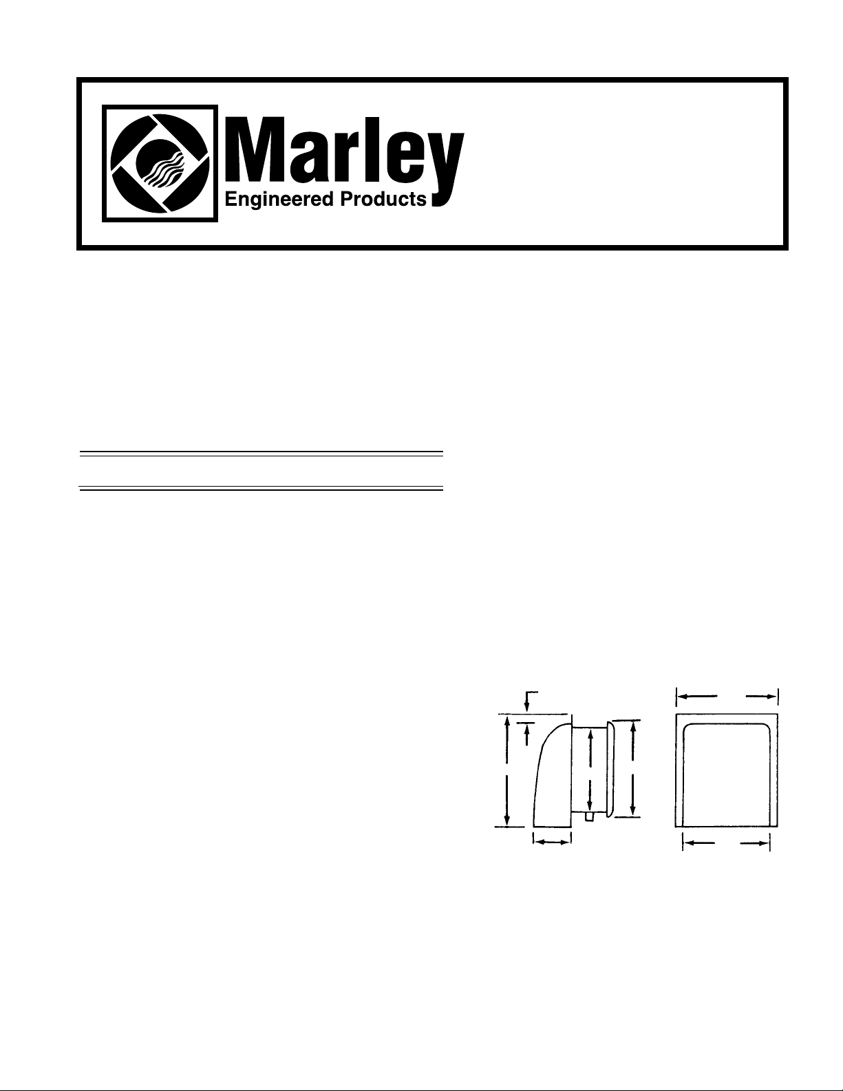
Dimensions
1”
12”
4”
9”
10
5
⁄8”
9
7
⁄8”
11
1
⁄4”
Fig. 1
Page 2
TOOLS
Installation of your Marley product is easy. No special technical
knowledge is needed. Only a few ordinary tools are required:
Screwdriver
Hammer
Saber saw, Keyhole saw, or Jig saw
Electric drill with bit
Wire cutters
Wire stripper
Wire nuts and general electrical supplies
Safety glasses
Ruler and straight edge
All hand tools should be insulated. Power tools should display the
UL Listed Mark.
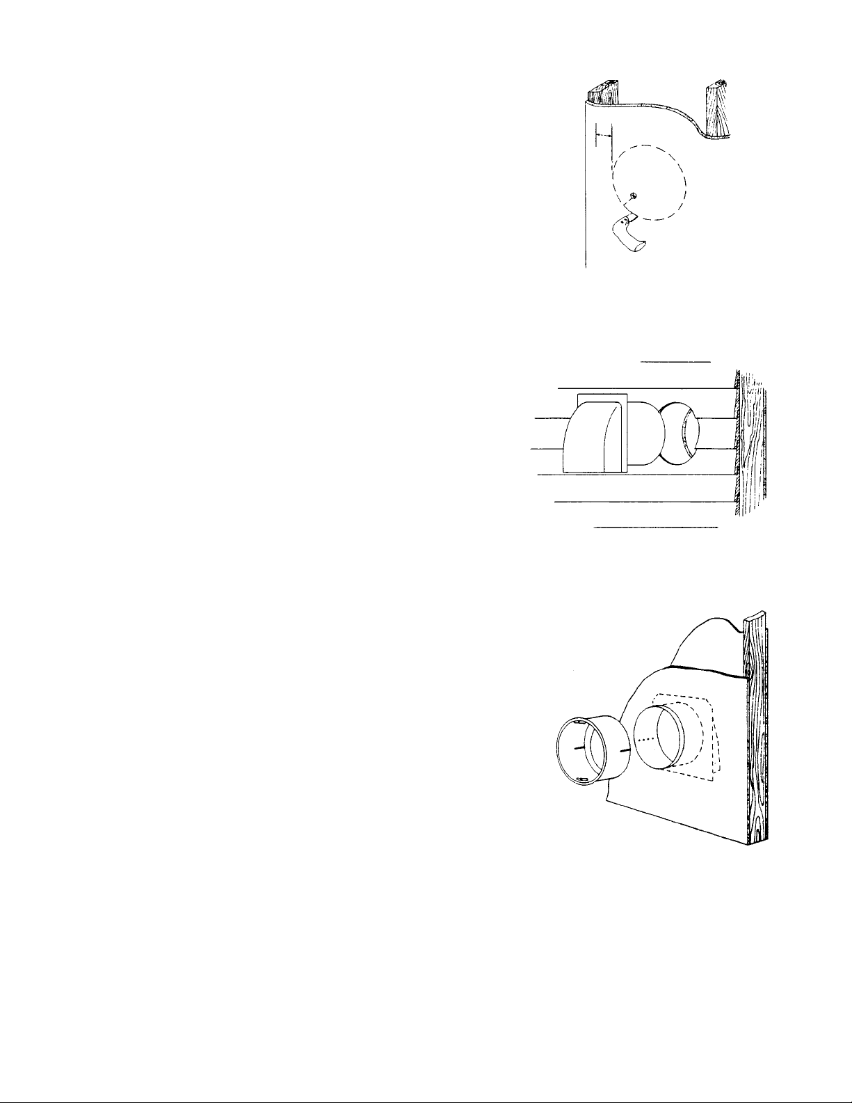
NEW HOME INSTALLATION
1. Cut round or square hole in sheathing at desired loca-
tion in wall. Round holes should be 91⁄8” in diameter.
Square holes should be 91⁄8” on a side. (See Figure 2.)
2. Install door and outside sleeve assembly from outside.
Caulk and level assembly before nailing door frame
tight.
Remove tape, permitting damper door to open. House
insulation can be worked around sleeve. (See Figure 3.)
3. Working from inside the house, slide inside sleeve into
place temporarily. Determine whether to remove one or
both knockouts from outside sleeve, permitting outlet
box to drop through. Remove knockouts from outside
sleeve. (See Figure 4.)
4. Slide inside sleeve into place again, and pull power
cable through outlet box opening. This will determine
length of power cable to ventilator. Power line should be
run to switch box holding toggle switch or optional timer.
Attach cable to outlet box, using an approved connector,
and splice cable to receptacle leads in outlet box cover.
Ground wire may be attached to grounding bolt in outlet
box. (See Wiring Diagram, Figure 5.)
5. Adjust inside sleeves so that flange will be flush with fin-
ished wall. Using metal screws, fasten inside housing to
outside housing. Screws are supplied with ventilator.
6. Push outlet box and outlet cover into place and fasten
with screws.
7. Install motor blade assembly. Engage keyhole slots
over screws in ventilator, twist and tighten, making sure
that blade is centered in sleeve. Be sure power is OFF,
then insert plug into receptacle.
8.
Attach grille with knob.
Fig. 2
Fig. 3
Fig. 4
1”
MIN.
- 2 -
Page 3

GROUND
SCREW
OUTLET BOX
EARTH
GROUND
120VAC
60Hz
SUPPLY
Fig. 5 - Wiring Diagram
CAUTION
BE SURE ALL WIRING COMPLIES WITH
LOCAL AND NATIONAL ELECTRICAL CODES AND
HOUSING IS PROPERLY GROUNDED.
TO INSTALL IN EXISTING HOMES
1. Determine location of ventilator. Check wall for studs
and obstructions.
2. Working inside wall first, draw a circle 91⁄8” in diameter
at determined location. Be sure opening is at least one
inch from studs. (See Figure 2.)
3. Carefully saw opening in plaster. Remove just enough
insulation to allow sleeve to pass through, exposing
sheathing. Mark center of the hole on the sheathing. At
this point, drill small hole to outside.
4. Now work from the outside. Using hole as a center
point, draw a circle on outside wall 91⁄8” in diameter.
Saw opening. In case of brick or stone, use hammer
and chisel to make opening. (See Figure 6.)
5. Install door and outside sleeve assembly from outside.
Caulk and level before nailing tight. Remove tape, permitting damper door to open. (See Figure 3.)
6. Working from inside the house, slide inside sleeve into
place temporarily. Determine whether to remove one or
both knockouts from outside sleeve, permitting outlet box
to drop through. Remove knockouts from outside sleeve.
(See Figure 4.)
7. Slide inside sleeve into place again and pull power
cable through outlet box opening. This will determine
length of power cable to ventilator. Power line should be
run to switch box holding toggle switch. For more efficient
operation, an optional timer is available. Attach cable to
outlet box, using approved connector, and splice cable to
receptacle leads in outlet box cover. Ground wire may be
attached to grounding bolt in outlet box. (See Wiring
Diagram, Figure 5.)
8. Adjust inside sleeve so that flange is flush with finished
wall. Using metal screws, fasten inside housing to
outside housing. Screws are supplied with ventilator.
9. Perform Steps 6-8 as for new homes to finish
installation.
TYPICAL
INSTALLATIONS
Fig. 6
STANDARD WALL SWITCH
- 3 -
Page 4

Part No. 5200-2531-000 PPD 035
2-00
LIMITED WARRANTY
Dear Customer,
Thank you for your interest in Marley Engineered Products bath fans. We’re sure you will enjoy
its benefits for many years to come. Please take a minute to fill out the following information and
keep it in your permanent records.
Date Purchased Date Installed
Model Number Serial Number
LIMITED WARRANTY
This Marley Engineered Products bath fant is warranted to be free of defects in material and
workmanship for 12 months from date of original purchase.
Elements for baseboard heaters are warranted for 10 years from the date of original purchase.
There is no other warranty, express or implied, except such as is expressly set forth herein.
Seller will not be liable for any general, consequential, or incidental damages, including without
limitation any damages for loss of use or loss of profits, for any breach of warranty or for negligence. Seller’s liability and buyer’s exclusive remedy are limited to the repair of defective goods
or the shipment of equivalent goods, or the granting of a reasonable allowance on account of any
defects, as the seller may elect.
To obtain performance under this warranty, you must:
1. Contact the Marley Engineered Products Service Department at 1-800-642-HEAT between
the hours of 8:30 a.m. and 5:00 p.m. E.S.T. Monday through Friday.
2. Provide the model number of the product, the date of installation, and state the nature of
the difficulty being experienced.
Products within warranty which have been installed and returned to the seller for repair will
be repaired and returned as used products. Repairs to products outside the warranty period
will be subject to labor and parts charges.
Some states have enacted legislation which (a) does not allow the inclusion of limitations on
incidental or consequential damages; (b) does not allow limitations on the length of a warranty period; (c) precludes exclusion, during the period of a limited warranty, of any implied
warranties of merchantability or fitness for purpose.
To the extent of such provisions being applicable in your state, the limitations in this warranty may not apply.
TO ENSURESAFE OPERATION
• Be sure that this unit is correctly installed and wired by a qualified installer in accordance
with the instructions and applicable NEC or equivalent codes.
• Be sure that operating instructions are followed and that moving and heating parts are
kept clean and free from obstructions.
Any warranties granted or liabilities assumed hereunder will not apply to goods that have
been damaged in transit, altered, repaired, installed or operated otherwise than in conformity with the above requirements for safe operation.
3. The Marley Engineered Products Service Representative will determine the best way
to resolve the difficulty.
HOW TO OBTAIN WARRANTY SERVICE AND
WARRANTY PARTS PLUS GENERAL INFORMATION
1. Warranty Service or Parts 1-800-642-4328
2. Purchase Replacement Parts 1-800-654-3545
3. General Product Information www.marleymep.com
Note: When obtaining service always have the following:
1. Model number of the product
2. Date of manufacture
3. Part number or description
470 Beauty Spot Rd. East
Bennettsville, SC 29512 USA
 Loading...