

Page 1
READ AND SAVE THESE INSTRUCTIONS
MODEL 1080
VENTILATOR
GENERAL
Model 1080 is designed for ceiling installation with vertical discharge through the ceiling by means of round duct.
Model 1080 is operated by means of a wall switch. Be careful when handling the motor blade assembly, to avoid
bending the blades.
UNPACKING
Unpack carefully. If there are missing components or hidden damage, immediately contact your distributor or the delivering carrier
concerning discrepancies.
IMPORTANT SAFETY INSTRUCTIONS
WARNING:
TO REDUCE RISK OF FIRE,ELECTRICAL SHOCK
OR INJURY T O PERSONS, OBSERVE THE FOLLOWING:
1. Do not use this fan with any Solid-State speed control device.
2. Use this unit only in the manner intended by the manufacturer.
If you have questions, contact the manufacturer .
3. Before servicing or cleaning unit, switch power off at service
panel and lock service panel to prevent power from being
switched on accidentally.
4. Installation work and electrical wiring must be done by qualified
person(s) in accordance with all applicable codes and standards, including fire-rated construction.
5. Sufficient air is needed for proper combustion and exhausting of
gases through the flue (chimney) of fuel burning equipment to
prevent back drafting. Follow the heating equipment manufacturer’s guideline and safety standards such as those published
by the national Fire Protection Association (NFPA), and the
American Society for Heating Refrigeration and Air Conditioning
Engineers (ASHRAE), and the local code authorities.
6. When cutting or drilling into wall or ceiling, do not damage electrical wiring or other hidden utilities.
7. Ducted fans must always be vented to the outdoors.
8. If this unit is installed over a tub or shower , it must be marked as
appropriate for the application.
9. NEVER place a switch where it can be reached from a tub or
shower.
10.CAUTION: For General Ventilating Use Only! Do not use to
exhaust hazardous or explosive materials and vapors.
1 1. Not for use in kitchens.
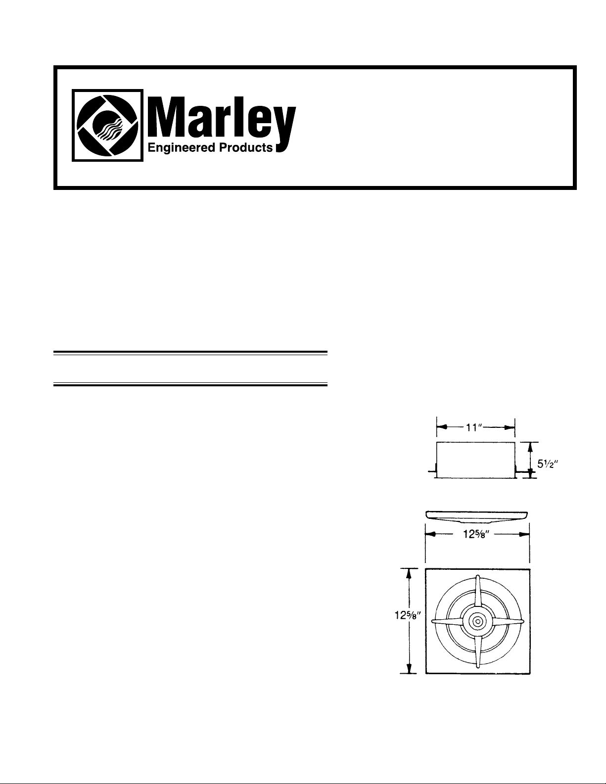
Dimensions
FIG. 1
Page 2
TOOLS
Installation of your Marley product is easy. No special technical knowledge is needed. Only a few ordinary
tools are required:
Screwdriver
Hammer
Saber saw, Keyhole saw, or Jig saw
Electric drill with bit
Wire cutters
Wire stripper
Wire nuts and general electrical supplies
Safety glasses
Ruler and straight edge
All hand tools should be insulated. Power tools should display the UL Listing Mark.
NEW HOME INSTALLA TION
1. Provide for a round hole 111⁄8” in diameter in the ceiling construction.
2. If a reducer is to be used to get to 8” diameter duct, remove the screws and mount it to the sleeve, so
that the screw holes align with the slots in the sleeve. Replace the screws.
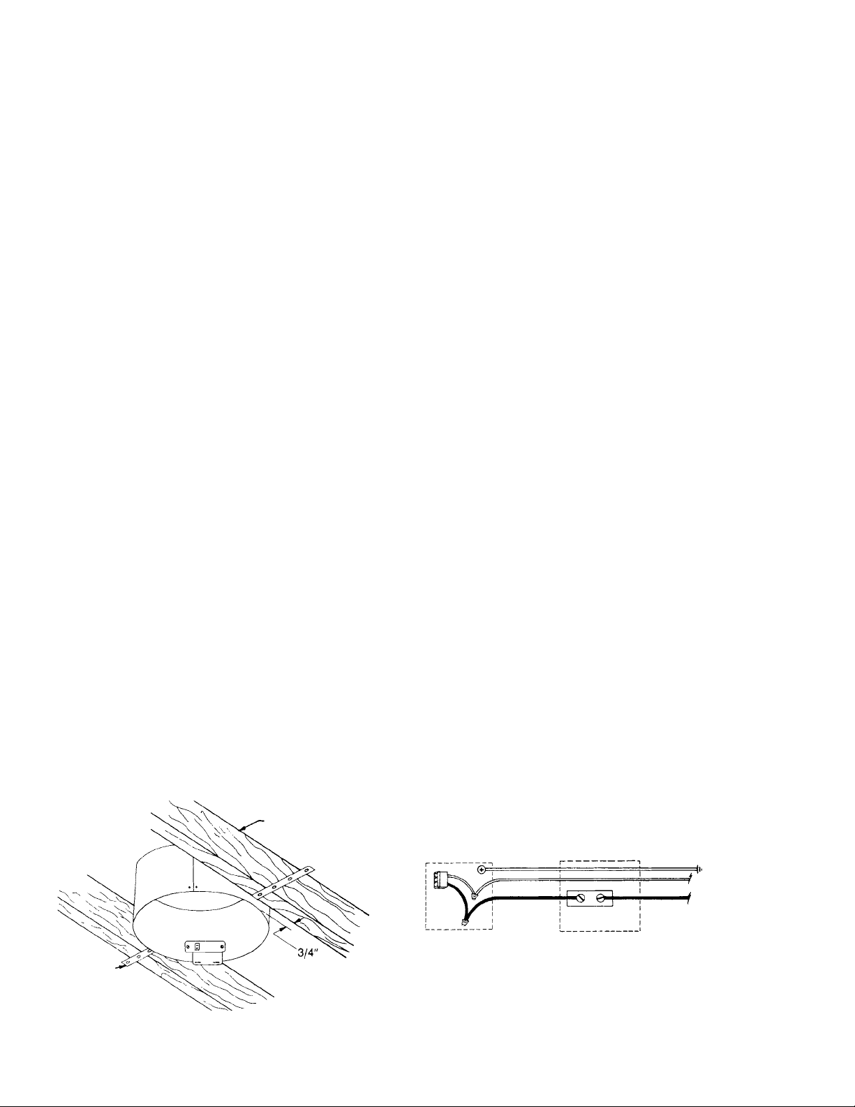
3. Attach brackets to sleeve with screws provided in the envelope. Nail or screw brackets to joist.
4. Adjust sleeve so that flange will be flush with the finished ceiling.
5. Pull power cable through outlet box opening. Attach cable to outlet box, using an approved connector .
Splice cable to receptacle leads in outlet box cover. Ground wire may be attached to grounding bolt in
outlet box. Power line should be run to switch box holding toggle or Model 1011ATimer. See Fig. 3.
6. Push outlet box and outlet cover into place and fasten with screws.
7. Install motor blade assembly . Insert bottom of motor bracket into holes in outlet box cover. Engage key
hole slot over screw in top of ventilator and tighten, making sure that blade is centered in sleeve. Be
sure power is off, then insert plug into receptacle.
8. Attach grille with knob.
9. Finish installation by adding sufficient 11” pipe to go through the roof and installing a Roof Cap. See Fig. 4.
FIG. 2
FIG. 3
STANDARDWALLSWITCH
GROUND
SCREW
OUTLET BOX
SWITCH BOX
EARTH GROUND
120VAC
60Hz
SUPPLY
CEILING JOIST
MOUNTING
BRACKET
Page 3

CAUTION
BE SURE ALL WIRING COMPLIES WITH LOCAL AND
NATIONAL ELECTRICAL CODES, AND HOUSING IS
PROPERLY GROUNDED.
TO INSTALL IN EXISTING HOMES
1. Determine location of ventilator . Check ceiling for joists and obstructions.
2. Draw a circle 1 11⁄8” in diameter at determined location. Be sure opening is at least 1” from joists.
3. Carefully saw opening in plaster. Remove just enough insulation to allow sleeve to pass through.
4. If a reducer is to be used, remove the screws and mount it to the sleeve, so that the screw holes align
with the slots in the sleeve. Replace the screws.
5. After attaching mounting brackets to sleeve, nail or screw brackets to joist, or simply support sleeve by
resting mounting brackets on lath or other ceiling material. See Fig. 2.
6. Adjust sleeve so that flange is flush with the finished ceiling.
7. Pull power cables through outlet box opening. Attach cable to outlet box, using an approved connector.
Splice cable to receptacle leads in outlet box cover. Ground wire may be attached to grounding bolt in
outlet box. Power line should be run to switch box holding toggle or Model 1011ATimer. See Fig. 3.
8. Push outlet box and outlet cover into place, and fasten with screws.
9. Install motor blade assembly . Insert bottom of motor bracket into holes in outlet box cover . Engage keyhole slot over screw in top of ventilator, and tighten, making sure that blade is centered in sleeve. Be
sure power is off, then insert plug into receptacle.
10.Attach grille with knob.
1 1. Finish installation by adding sufficient 1 1” pipe to go through the roof and installing a Roof Cap. See Fig. 4.
ROOF CAP
TO ROOF CAP
11” DUCT (8” WITH REDUCER)
REDUCER (OPTIONAL)
FIG. 4
Page 4

LIMITED WARRANTY
Dear Customer,
Thank you for your interest in Marley Engineered Products bath fans. We’re sure you will
enjoy its benefits for many years to come. Please take a minute to fill out the following
information and keep it in your permanent records.
Date Purchased Date Installed
Model Number Serial Number
LIMITED WARRANTY
This Marley Engineered Products bath fan is warranted to be free of defects in material
and workmanship for 12 months from date of original purchase.
Elements for baseboard heaters are warranted for 10 years from the date of original
purchase.
There is no other warranty, express or implied, except such as is expressly set forth herein.
Seller will not be liable for any general, consequential, or incidental damages, including without limitation any damages for loss of use or loss of profits, for any breach of warranty or for
negligence. Seller’s liability and buyer’s exclusive remedy are limited to the repair of defective goods or the shipment of equivalent goods, or the granting of a reasonable allowance on
account of any defects, as the seller may elect.
To obtain performance under this warranty, you must:
1. Contact the Marley Engineered Products Service Department at 1-800-642-HEAT
between the hours of 8:30 a.m. and 5:00 p.m. E.S.T. Monday through Friday.
2. Provide the model number of the product, the date of installation, and state the nature
of the difficulty being experienced.
Products within warranty which have been installed and returned to the seller for repair
will be repaired and returned as used products. Repairs to products outside the warranty period will be subject to labor and parts charges.
Some states have enacted legislation which (a) does not allow the inclusion of limitations
on incidental or consequential damages; (b) does not allow limitations on the length of a
warranty period; (c) precludes exclusion, during the period of a limited warranty, of any
implied warranties of merchantability or fitness for purpose.
To the extent of such provisions being applicable in your state, the limitations in this
warranty may not apply.
TO ENSURE SAFE OPERATION
• Be sure that this unit is correctly installed and wired by a qualified installer in accordance
with the instructions and applicable NEC or equivalent codes.
• Be sure that operating instructions are followed and that moving and heating parts
are kept clean and free from obstructions.
Any warranties granted or liabilities assumed hereunder will not apply to goods that have
been damaged in transit, altered, repaired, installed or operated otherwise than in
conformity with the above requirements for safe operation.
3. The Marley Engineered Products Service Representative will determine the best
way to resolve the difficulty .
Part No. 5200-2535-000 PPD 035
2-00
HOW TO ORDER REPAIR PARTS
In order to obtain any needed repair or replacement
parts, warranty service or technical information, please
contact Marley Engineered Products Service Center tollfree by calling 1-800-642-HEAT.
When ordering repair parts, always give the information listed as follows:
1. The Part Number
2. The Model Number
3. The Part Description
4. Date of Manufacture
470 Beauty Spot Rd. East
Bennettsville, SC 29512 USA
 Loading...