


Wall Mount LED Signal Tower with Built-in Audible Alarm
54
-30~+50
85d
B
QWT
Thank you for purchasing Qlight’s products. Please read this user manual carefully
prior to installation and operation to ensure safe and correct use.
■
Warning and Caution
Precautions for Safety
Failure to follow the instructions below may cause a loss of life or serious physical injury.
1. During wiring or maintenance, please completely turn o the power of the product. (Failure to follow this may lead to an electric shock.)
2. Do not install the product in locations that subjects it to excessive dust or water other than the conditions designated by the IP protection
ratings indicated for each product. (Failure to follow these instructions may cause a re to the product, electric shock, physical injury,
malfunction or damage to the product.)
3. Do not alter or repair this product. If maintenance or repair service is required, please contact your local Qlight contact point. (Failure to
follow these instructions may lead to re, electric shock, or product damage.)
4. Please apply the correct voltage to the product. (Failure to follow these instructions may lead to re, electric shock, or product damage.)
5. When the product is applied to a condition that may impact lives or property, please make sure to have a double safety device. (Failure to
follow this may cause damage to property, re, electric shock and loss of life.)
Precautions for Correct Use
Failure to follow the proper instructions may cause damage to property, the product, and or malfunction of
the product that would void the warranty.
1. Please remove any objects that can interrupt ventilation around the product.
2. Please turn o the power of the product immediately if it fails to operate properly.
3. Carefully wire the product according to each product’s specication.
4. Please be careful in preventing chemicals such as thinner, benzene, etc. in contact with the surface of the product.
5. Do not apply excessive force/impact to the product.
6. Failure to follow any of the instructions above may cause malfunction or damage to the product, re, and electric shock.
Ordering Specication
QWTL
[Model number]
| | | |
• QWTL
• QWTL - BZ
• QWTLF
• QWTLF - BZ
-
3
[Layer] [Voltage] [Color]
•
1-1Layer
•
2-2Layers
•
3-3Layers
•
4-4Layers
•
5-5Layers
-
110/220
• 12 - DC12V
• 24 - DC24V
• 110/220 - AC110V-220V
-
RAG
R-Red
A-Amber
G-Green
B-Blue
W-White
QWT
Please scan the QR
code for more detailed
product information.
www.qlight.com
1

70
Specication
Model
Number
QWTL
Steady type
QWTL - BZ
Steady type with
built-in buzzer
QWTLF
Steady/Flashing
type
QWTLF - BZ
Steady/ Flashing
type with built-in
buzzer
Layer
Voltage Current
AC/DC12V 0.065A
1
AC/DC24V 0.050A
AC110V-220V Max. 0.025A
AC/DC12V 0.130A
2
AC/DC24V 0.100A
AC110V-220V Max. 0.050A
AC/DC12V 0.195A
3
AC/DC24V 0.150A
AC110V-220V Max. 0.075A
AC/DC12V 0.260A
4
AC/DC24V 0.200A
AC110V-220V Max. 0.100A
AC/DC12V 0.325A
5
AC/DC24V 0.250A
AC110V-220V Max. 0.125A
Certicate
DC only
DC24V
only
Weight
0.34kg
0.34kg
0.36kg
0.41kg
0.41kg
0.43kg
0.48kg
0.48kg
0.50kg
0.55kg
0.55kg
0.57kg
0.62kg
0.62kg
0.64kg
Color
R-Red
R-Red
G-Green
R-Red
A-Amber
G-Green
R-Red
A-Amber
G-Green
B-Blue
R-Red
A-Amber
G-Green
B-Blue
W-White
Current Specications
Voltage
Condition
Light
(per Layer)
Buzzer
AC/DC12V AC/DC24V AC110-220V
0.065A 0.050A Max 0.025A
0.034A 0.078A Max 0.016A
• Protection rating : IP54
• Ambient operating temperature : -30°C to +50°C
※
AC type model has a free-voltage range of AC100V-240V.
Dimensions
(Unit : mm)
QWT
6-Ø4 HOLES
Ø70
LAYER L
1 121
2 162
3 203
4 244
5 285
L
41
40 40
70
76
269
Ø13
43 41 41 41 41
21
8
54
CABLE ENTRY
27.5
Installation Environment and Protection Rating
•
This product is designed for indoor use with an enclosure ingress protection rating of IP54.
•
If the product is installed in locations with excessive dust or water other than the designated IP protection rating indicated (IP54),
it may cause malfunction or damage to the product.
•
For further information, please visit our website at http://www.qlight.com.
2

Wiring Instructions
•
QWT series can be wired with either an external contact or a transistor.
•
When using a transistor, please choose the NPN transistor or PNP transistor which best matches the voltage and product type, then
connect them correctly according to the wiring diagram below.
•
For QWTDLF model, user can choose light function between steady and ashing mode through wiring conguration.
External Contact Transistor
QWTL-DC QWTL-DC
DC
Steady
Red(R)
Amber(A)
Green(G)
1
Blue(B)
2
White(W)
3
Brown(BN)
4
5
Black(BK)
Fuse
Steady
Layer1
Layer2
Layer3
Layer4
Layer5
Buzzer
Power
1
2
3
4
5
External Contact
External Transistor-NPN
Red(R)
Amber(A)
Green(G)
Blue(B)
White(W)
Brown(BN)
Steady
Fuse
Black(BK)
Layer1
Layer2
Layer3
Layer4
Layer5
Buzzer
Power
1
2
3
4
5
External Transistor-PNP
Red(R)
Amber(A)
Green(G)
Blue(B)
White(W)
Brown(BN)
Steady
Fuse
Black(BK)
Layer1
Layer2
Layer3
Layer4
Layer5
Buzzer
Power
DC
Steady/
Flashing
AC
Steady
QWTLF-DC QWTLF-DC
Fuse
External Contact
Layer1
Layer2
Layer3
Layer4
Layer5
Buzzer
Steady
Common
Power
Red(R)
Amber(A)
Green(G)
Blue(B)
White(W)
Brown(BN)
1
2
Black(BK)
3
4
5
White(W)
Black(BK)
Common
Red(R)
Amber(A)
Green(G)
Blue(B)
White(W)
Brown(BN)
1
2
3
4
5
Black(BK)
White(W)
Black(BK)
External Transistor-PNP
Common
Steady
Common
Fuse
Flash
Layer1
Layer2
Layer3
Layer4
Layer5
Buzzer
Layer1
Layer2
Layer3
Layer4
Layer5
Power
QWTL-AC QWTL-AC
Red(R)
Amber(A)
Green(G)
Blue(B)
White(W)
1
Brown(BN)
2
3
4
5
Black(BK)
White(W)
Black(BK)
Common
Fuse
External Contact
Layer1
Layer2
Layer3
Layer4
Layer5
Buzzer
Steady
Common
Power
Red(R)
Amber(A)
Green(G)
Blue(B)
White(W)
1
Brown(BN)
2
3
4
5
Black(BK)
White(W)
Black(BK)
External Transistor-PNP
Steady
Common
Fuse
Layer1
Layer2
Layer3
Layer4
Layer5
Buzzer
Power
QWTLF-AC QWTLF-AC
Fuse
External Contact
Layer1
Layer2
Layer3
Layer4
Layer5
Buzzer
Steady
Common
Power
Red(R)
Amber(A)
Green(G)
Blue(B)
White(W)
Brown(BN)
Gray(GR)
1
2
3
4
5
Black(BK)
White(W)
Black(BK)
Red(R)
Amber(A)
Green(G)
Blue(B)
White(W)
AC
Steady/
Flashing
•
DC Steady type : Power/ Signal line specication : UL1007 AWG22 (0.3sq) 400mm
•
AC Steady type, AC/ DC Steady/ Flashing type : Power line specication : UL1015 AWG18 (0.75sq)X2C 400mm
Brown(BN)
1
2
3
Black(BK)
4
5
Gray(GR)
White(W)
Black(BK)
Common
External Transistor-PNP
Common
Common
Fuse
Signal line specication : UL1007 AWG22 (0.3sq) 400mm
3
Steady
Flash
Layer1
Layer2
Layer3
Layer4
Layer5
Buzzer
Layer1
Layer2
Layer3
Layer4
Layer5
Power
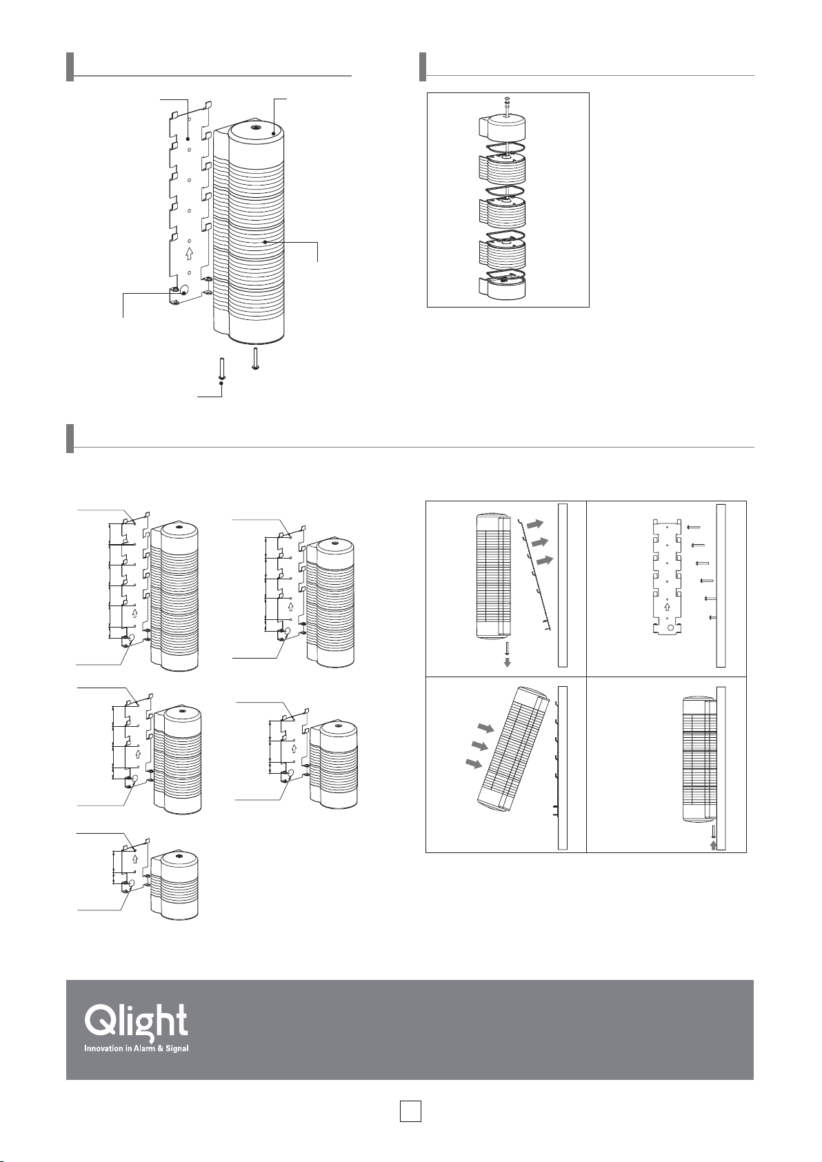
Parts Denition
M4-25 BOLT
6-Ø4 HOLES
Replacing/ Rearranging LED Lens Units
Mounting Bracket
(SPCC)
Head Cover(ABS)
①
②
Please ensure the power is off
before replacing or rearranging
the LED units. Please carefully
follow the following instructions.
③
④
LED Unit (PC)
Rubber Backing
(PVC)
1. Remove the head cover (②) by loosening the xing screw (①).
③
2. Remove the LED unit by pulling it (
) upward.
3. Replace or rearrange the LED units.
4. Assemble in the reverse order of removing the LED units, Be
Screw(M4×25mm)
careful not to let the rubber ring(④) tted on the top of each unit
come off.
Installation
• The mounting bracket needs to be installed on the mounting surface before xing the product body onto the mounting bracket.
• Drill the proper number of mounting holes in accordance with the number of LED lens units, refer to the installation diagrams below.
Ø13 CABLE
ENTRY
4-Ø4 HOLES
Ø13 CABLE
ENTRY
2-Ø4 HOLES
Ø13 CABLE
ENTRY
5-Ø4 HOLES
41414141
4141
414321
43
21
4141
43
21
4321
Ø13 CABLE
ENTRY
3-Ø4 HOLES
Ø13 CABLE
ENTRY
41
43
21
①
M4-25 BOLT
③ ④
① Remove the mounting bracket from the product by removing two M4
②
M4-25 BOLT
screws from the speaker unit.
② Mount the mounting bracket to the mounting surface.
③ Hook the rear of the head cover to the upper bracket, then push the
body against the mounting bracket.
④ After tightly attaching the product body to the mounting bracket, tighten
the two M4 screws removed in step ① at the bottom of the speaker unit.
Product Operation Inquiry / Customer Support +82-55-328-4082
You can expect prompt service if you have exact information such as model name, symptom, telephone number and address.
※
ALL PRODUCT, PRODUCT SPECIFICATIONS AND DATA ARE SUBJECT TO CHANGE WITHOUT NOTICE TO IMPROVE
RELIABILITY, FUNCTION OR DESIGN OR OTHERWISE.
Head office : A-412, 579 Kyungin-Ro, Guro-Gu, Seoul, Korea (Postal Code : 08212)
Factory : 185-25, Mukbang-Ro, Sangdong-Myeon, Gimhae-Si, Gyeongsangnam-Do, Korea (Postal Code : 50805)
4
www.qlight.com
EN-1712A
 Loading...