

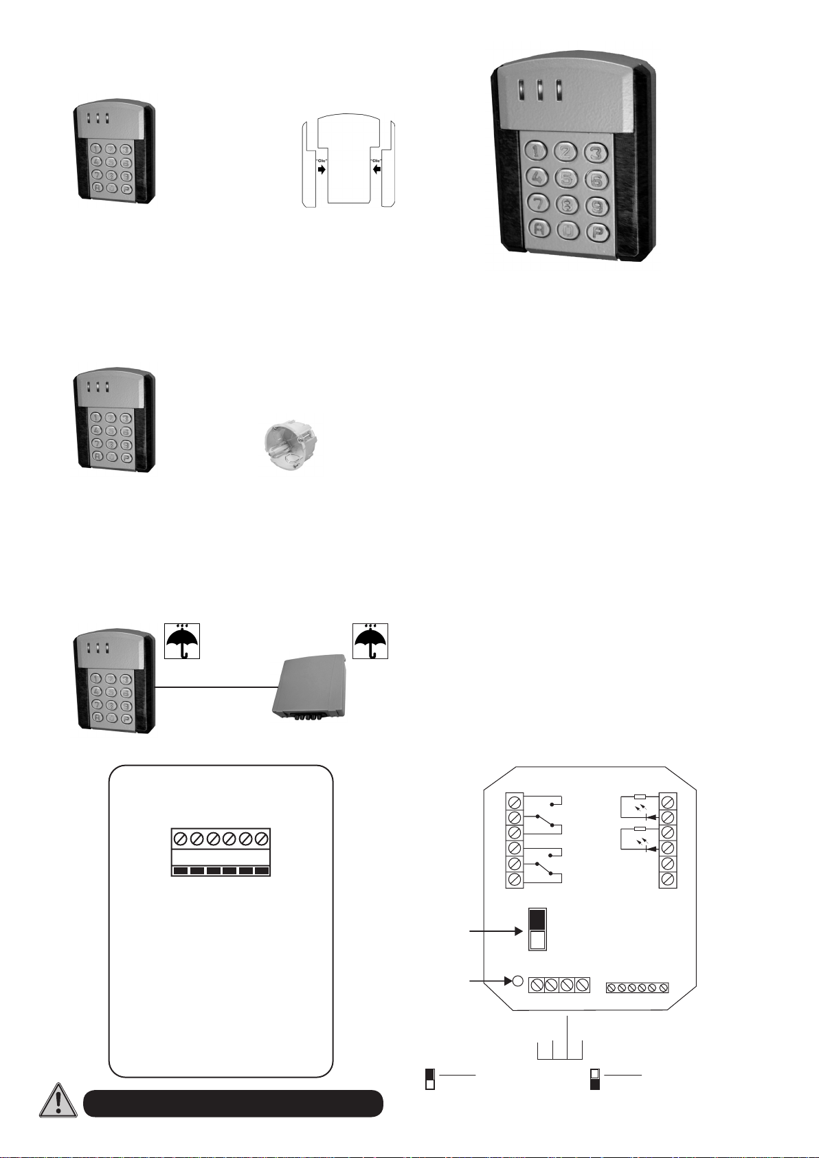
TECLADO DE SUPERFICIE
Con los 2 tornillos
de seguridad
108 x 83 x 19 mm
TECLADO EMPOTRADO
En fondo de cajetín
eléctrico estandar
Entre ejes : 60
+
108 x 83 x 19 mm
ELECTRÓNICA REMOTA DE SUPERFICIE
QKEYSUNS
CARACTERÍSTICAS TÉCNICAS
• Tensión de alimentación automática: 12 a 24 V CA/CC Alto rendimiento
• Consumo : Mín. 30 mA - Máx. 130 mA
• Temperatura de funcionamiento : - 30°C à + 50°C
• Estanqueidad teclado : IP66
• Estanqueidad electrónica remota : de supercie IP55, empotrado no estanco
• Código maestro de acceso a la programación
• 250 códigos usuario, programables de 1 a 8 cifras cada uno
• Autoprotección programmable
• 2 salidas a relés 5 A, NA/NC
• Conguración de salida programable en Marcha/Parada o en impulsional
000 a 240 segundos
• Teclas metálicas
• Tornillos de seguridad
• 3 colores intercambiables (kit suministrado)
• 2 indicadores luminosos disponibles
• Iluminación automática o permanente del teclado
• Indicador sonoro de las operaciones en curso (BIP)
• Entrada pulsador para SALIDA 1
• Entrada detección puerta (puerta forzada o tiempo máximo de apertura)
• Entrada reloj (libre acceso por tecla P o control horario)
• Bloqueo de seguridad : trás 8 códigos incorrectos, señal de alerta durante
30 segundos o activación de la alarma
• Modos seguridad, solidario, accelerado y pánic para activar alarma
• Modo automático y manual para activar automatismos
El teclado está concebido para funcionar con hasta 50 m de cable.
En caso de cable más largo, no podemos garantizar el buen funcionamiento
del producto.
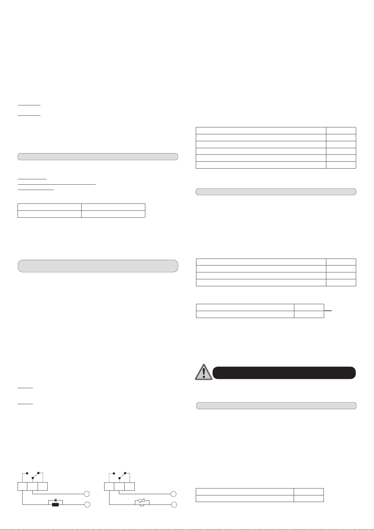
160 x 150 x 60
DC+
RED LED
GREEN LED
EL TECLADO ES UN SUN-S-WDT EN MODO WIEGAND PARA SUN-S
W1/DATA
DC-GROUND
WØ/CLOCK
CONEXIÓN
SALIDA 2
SALIDA1
Puente de
programación
Indicador
amarillo
Posición alta : N
Marcha normal
del teclado
Salida de fábrica : Posición N
NA
C
{
NC
NA
C
{
NC
N
P
I GT C PB 1 2 3 4 5 6
{
Reloj
Puerta
TECLADO
Pulsador
Posición baja : P
Permite acceder a la memoria
sin necesidad de marcar el código
maestro.
-
+
-
+
ALIM
ER2
Piloto
{
indicador verde
Piloto
{
Indicador rojo
Alimentación
12/24 v
{
CA-CC
Cable del teclado :
1 -W1/DATA
2 - DC+
3 - WØ/CLOCK
4 - DC-GROUND
5 - RED LED
6 - GREEN LED
PROGRAMACIÓN SIMPLIFICADA
codigo n° 001
codigo n° 151
borrar código n°3
borrar todos los codigos excepto código maestro
borrar código maestro
su código
su código
Electrocerradura
Electrocerradura
¡IMPORTANTE! Ante todo, es imprecindible conectar el teclado con su
electrónica remota :
• PROGRAMACIÓN DEL CÓDIGO MAESTRO: El código de origen es 0 0 0
Pulsar 0 0 0 y P Se enciende el indicador amarillo
Pulsar 0 y 0 0 0 Pulsar el nuevo código maestro de 1 a 8 cifras
Exemple 5823: Pulsar 0 y 0 0 0 Pulsar 5 8 2 3 luego A y P
Se apaga el indicador amarillo
• ENTRAR EN PROGRAMACIÓN
Basta con pulsar su nuevo código maestro 5 8 2 3 y P
Se enciende el indicador amarillo
• PROGRAMAR LOS CÓDIGOS USUARIO DE 001 A 250
Ejemplo18126 : Pulsar 0 luego 0 0 1y 1 8 1 2 6 y A
Ejemplo 057558 : Pulsar 0 luego 1 5 1 y 0 5 7 5 5 8 y A
• PROGRAMAR EL TIEMPO DE IMPULSÓN DE 001 A 240 SEGUNDOS O
MARCHA/PARADA
Ejemplo de impulsion de 6 segundos relé 1: Pulsar 1 luego 0 0 6 y A
Ejemplo Marcha/Parada relé 2: Pulsar 2 luego 0 0 0 y A
: Pulsar 0 luego 0 0 1 pulsar el código de 1 a 8 cifras
: Pulsar 0 luego 1 5 1 pulsar el código de 1 a 8 cifras
Códigos 001 a 150 en SALIDA 1 - Códigos 151 a 250 en SALIDA 2
BORRAR LOS CÓDIGOS
• PROGRAMACIÓN DE LA ILUMINACIÓN
Iluminación automática 5 000 A
Iluminación permanente 5 001 A
• FUNCIÓN DE LAS TECLAS
Tecla ø : Programación códigos
Tecla 1 : Tempo relés 1
Tecla 2 : Tempo relés 2
Tecla 5 : Iluminación, control acceso
: Pulsar 9 luego 0 0 3 y A
: Pulsar 9 luego 2 5 5 (BIIIIP) y A
: Pulsar 9 luego 0 0 0 y A
Tecla 6 : Gestión de puerta
Tecla 8 : Automátismo o alarma
Tecla 9 : Borrar códigos
PULSAR (P) PARA SALIR DE LA PROGRAMACIÓN
SE APAGA EL INDICADOR AMARILLO
PROCEDIMIENTO DE EMERGENCIA
EN CASO DE PERDIDA O DE OLVIDO DE SU CÓDIGO MAESTRO, ESTA
OPERACIÓN LE PERMITE ENTRAR EN PROGRAMACIÓN PARA INTRODUCIR UNO
NUEVO :
1) Desconectar la alimentación y esperar 5 segundos,
2) Colocar el puente de programación en la posición baja P,
3) Conectar de nuevo la alimentación
4) Colocar el puente de programación en la posición N,
se enciende el indicador amarillo,
5) Pulsar la tecla P, se enciende el indicador amarillo,
6) Pulsar la tecla 0 luego 0 0 0 ,
7) Pulsar el código maestro deseado de 1 à 8 cifras,
8) Validar con la tecla A
9) Pulsar P para salir de la programación
ESPECIAL CONTROL DE ACCESO
Tiempo máximo de apertura :
Si la puerta permanece abierta más tiempo de lo programado, el relé n°2 bascula
Cablear un detector de puerta entre la entrada GT y C.
• Programar su entrada detector de puerta (GT) - Detección a la apertura del contacto.
Máx. 2400 segundos
Entrada puerta forzada :
Al entrar forzando la puerta, el relé 2 bascula. Cablear un
detector de puerta entre la entrada GT y C
Control horario :
Cuando el reloj cierra el contacto, los usuarios 001 a 100 no tienen acceso. Cablear un
reloj entre la entrada I y C
Libre acceso con la tecla P : (con reloj exterior)
Cuando el reloj cierra el contacto, el hecho de pulsar la tecla P activa el relé n°1
(puerta). Cablear el contacto del reloj entre la entrada I y C.
Modo tiempo max de apertura (ejemplo : 140 sec) 6 014 A
Modo puerta forzada 6 000 A
Modo control horario e iluminación automática 5 010 A
Modo control horario e iluminación permanente 5 011 A
Modo libre acceso e iluminación automática 5 000 A
Modo libre acceso e iluminación permanente 5 001 A
ESPECIAL ALARMA
Pulsar 8 luego 000 y A para cancelar los modos
Modo autoprotección : si se arranca el teclado, el relé 2 bascula
Modo seguridad : trás 8 códigos incorrectos, el relé 2 bascula
Modo solidario : Desconecta la alarma (relé 2) al abrir la puerta (relé 1). Los códigos
001 a 150 basculan la SALIDA 1 y activan la SALIDA 2. Para desactivar la SALIDA
2, hay que utilizar los códigos 151 a 250.
Modo accelerado : para desactivar la SALIDA 2, pulsar las dos primeras teclas de
los códigos 151 a 250. Para activar la SALIDA 2, pulsar los códigos completos.
Modo autoprotección 8 100 A
Modo seguridad 8 010 A
Modo solidario 8 003 A
Modo accelerado 8 004 A
Es posible combinar diferentes modos según las necesidades de la instalación
Modo autoprotección y seguridad 8 110 A
Modo autoprotección, seguridad y accelerado 8 114 A
Código panic : En el ejemplo, la SALIDA 2 está utilizada como PANIC de la SALIDA 1.
El código 157558 es el código panic.
SALIDA 1 : código 001 … 057558
SALIDA 1 : código 002 … 157558
SALIDA 2 : código151 … 157558
Ejemplos
UTILIZACIÓN DIARIA
: 18126 : Pulsar1 8 1 2 6 y A
: 057558 : Pulsar 0 5 7 5 5 8 y A
• PULSADOR
Al apretar el pulsador, el relé 1 bascula. Cablear entre la entrada BP y C.
La SALIDA 1 se activa durante 6 segundos
La SALIDA 2 se activa, marcando de nuevo su código y
validando con A, se desactiva la SALIDA 2
CONEXIÓN DE UNA ELECTROCERRADURA
Para programar las funciones especiales (control de acceso, alarma y
automatismos), hay que entrar primero en modo de programación. Ver capítulo
programación simplicada (punto 3).
C
NA
EN CORRIENTE CONTINUA
NC
Diodo BY 251
NA
-
+
EN CORRIENTE ALTERNA
C
NC
Varistor de voltaje adecuado
NO SON COMPATIBLES LOS MODOS CONTROL DE ACCESO Y ALARMA
ESPECIAL AUTOMATISMOS
Pulsar 8 luego 000 y A para cancelar los modos
Para entrar en estos modos, hay que introducir un código de usuario y validar con la
tecla A. El indicador amarillo parpadea y el zumbador produce un zumbido. Para salir
de estos modos, basta con pulsar la tecla P.
Modo manual : permite desplazar el automatismo en un sentido, al apretar la tecla 4,
mientras que al apretar la tecla 6 desplaza el automatismo en el sentido opuesto. Tecla
4 activa relé 1 - Tecla 6 activa relé 2
Modo automático : permite desplazar el automatismo en un sentido, con el impulso
de la tecla 4, hasta n del tiempo del relé o pulsar la tecla A, Ø ó P. El hecho de pulsar
la tecla 6 desplaza el automatismo en el sentido puesto. La tecla Ø detiene el
automatismo. Tecla 4 activa relé 1 - Tecla 6 activa relé 2 - la tecla Ø desactiva relés.
~
~
Modo manual 8 001 A
Modo automático 8 002 A

SURFACE KEYPAD
108 x 83 x 19 mm
S
With 2 safety
screws
INBUILT KEYPAD
At the bottom of a
standard electrical box
Between axes : 60
+
108 x 83 x 19 mm
REMOTE ELECTRONICS SURFACE
QKEYSUNS
TECHNICAL FEATURES
• Automatic power voltage: 12 to 24 V AC/DC High performance
• Consumption: Min. 10 mA - Max. 130 mA
• Operating temperature: - 30°C to + 50°C
• Watertightness of keypad : IP66
• Watertightness of remote electronics : surface IP55, inbuilt not watertight
• Master code for access control
• 250 programmable user codes each one from 1 to 8 digits
• Non-volatile EEPROM memory
• Programmable self-protection
• 2 relays outputs 5 A, NA/NC
• Programmable output conguration for operation/Stop or push button (000 to
240 seconds)
• Metal keys
• Safety screws
• 3 interchangeable colours (kit supplied)
• 2 power-on indicators available
• Automatic or constant keypad ilumination
• Audible signal for operations in progress (BEEP)
• Push-button input available for OUTPUT N°1
• Door detection input (forcing door or maximum opening time)
• Clock input (free access with key P or time allocation)
• Security : after 8 incorrect codes entered, blocks and emits an alarm signal for
30 seconds or activation of alarm
• Security, twin, accelerated and panic modes for alarm connection
• Automatic and manual modes for automation connection
The keypad is designed to work with a 50 m cable maximum.
If the cable is extended,we won’t be able to guarantee the optimum working of
the product.
160 x 150 x 60
CONNECTION
DC+
RED LED
GREEN LED
THE KEYPAD IS A SUNSWDT IN WIEGAND MODE FOR SUNS
W1/DATA
DC-GROUND
WØ/CLOCK
OUTPUT 2
OUTPUT 1
Programming
bridge
Yellow
light
{
{
High position : N
Normal keypad
operation
Factory setting : Position N
NO
C
NC
NO
C
NC
N
P
I GT C PB 1 2 3 4 5 6
{
Clock
Door
KEYPAD
Push-button
Position basse : P
Allows access to the memory
without having to key
the master code.
-
+
-
+
POWER
ER2
Green pilot light
{
Red pilot light
{
Power supply
12-24 v
{
AC/DC
Keypad cable :
1 -W1/DATA
2 - DC+
3 - WØ/CLOCK
4 - DC-GROUND
5 - RED LED
6 - GREEN LED

EASY PROGRAMMING
Electro-lock
Electro-lock
IMPORTANT! it is imperative that the keypad should be connected to its remote
electronics.
• PROGRAM A MASTER CODE : The code of origine is 0 0 0
Key in 0 0 0 then P The yellow light comes on
Press 0 and 0 0 0 Key in the new master code (1 to 8 digits)
Example 5823 : Press 0 and 0 0 0 Key in 5 8 2 3 then A and P
The yellow light goes o
• ENTER PROGRAMMING MODE
Just key in your new master code 5 8 2 3 and P
The yellow light comes on
• PROGRAM USER CODES FROM 001 TO 250
code n° 001 : Press 0 then 0 0 1 Key in the code (1 to 8 digits)
Example 18126 : Press 0 and 0 0 1 then 1 8 1 2 6 and A
code n° 151 : Press 0 and 1 5 1 key in the code (1 to 8 digits)
Example 057558 : Press 0 and 1 5 1 then 0 5 7 5 5 8 and A
• PROGRAM THE PUSH-BUTTON TIME (001 TO 240 SECONDS) OR IN
OPERATION/STOP
Example of push-button time of 6 seconds relay 1: Press 1 then 0 0 6 and A
Example of operation/Stop relay 2: Press 2 then 0 0 0 and A
Codes 001-150 to OUTPUT 1 - Codes 151-250 to OUTPUT 2
ERASE THE SERVICE CODES
erase code n°3 : Composez 9 puis 0 0 3 et A
erase all codes except the master code : Press 9 then 2 5 5 (BEEEP) and A
erase master code : Press 9 then 0 0 0 and A
• PROGRAM ILUMINATION
Automatic light 5 000 A
Permanent light 5 001 A
Key ø : Codes programming
key 1 : Relay 1 tempo
key 2 : Relay 2 tempo
key 5 : Ilumination, access control
Key 6 : Door management
Key 8 : Alarm or automation
Key 9 : Code erasement
PRESS (P) TO EXIT PROGRAMMING
THE YELLOW LIGHT GOES OFF
EMERGENCY PROCEDURE
IF YOU LOSE OR FORGET YOUR MASTER CODE, THIS OPERATION ALLOWS YOU
TO ENTER THE PROGRAM AND INPUT A NEW ONE :
1) Disconnect the power supply and wait 5 seconds,
2) Put the programming bridge in the low position P,
3) Reconnect the power supply
4) Put the programming bridge in the high position N,
the yellow light comes on,
5) Press key P, the yellow light comes on,
6) Press key 0 then 0 0 0 ,
7) Key in the master code you want, (1 to 8 digits)
8) Validate the operation with key A
9) Press key P to exit programming
ACCESS CONTROL FUNCTIONS
Maximum door opening time:
If the door is still opened when the relay tempo is over, the second relay is activated.
Wire a door detector between input GT and C.
• Program your door detector input (GT)- Detection when contact is opened.
Max. 2400 seconds
Door Break in input: when the door is broken in, the second relay is activated.
Connect a door contact between GT and C connectors.
Time allocation :
When the clock closes the contact, codes from 001 to 100 are not accepted.
Wire a clock between input I and C.
Free access with key P : (with external clock)
When the clock closes the contact, key in P activate relay 1 (door). Wire the contact of
the clock between input I and C.
Maximum door opening time mode (ex : 140 sec.) 6 014 A
Door break in mode 6 000 A
Hour control and automatic ilumination mode 5 010 A
Hour control and permanent ilumination mode 5 011 A
Free access and automatic ilumination mode 5 000 A
Free access and permanent ilumination mode 5 001 A
ALARM FUNCTIONS
Press 8 then 000 and A to cancel the modes
Self-protection mode : Relay 2 activates when keypad is teared o.
Security mode : after 8 incorrect codes, relay 2 activates
Twin mode : Codes from 001 to 150 activate relay 1 (open a door) and deactivate
the relay 2 (alarm o). Once the relay 2 is o, those codes are still operating to open
but do not change the second relay status. To RE activate the relay 2, just you have
to use codes from 151 to 250.
Accelerated mode : To deactivate relay 2, press the 2 rst digits of the codes from
151 to 250. To activate relay 2, you have to press the complete codes.
Self-protection mode 8 100 A
Security mode 8 010 A
Twin mode 8 003 A
Accelerated mode 8 004 A
It is possible to combine several modes regarding the needs of the installation.
Self-protection and security mode 8 110 A
Self-protection, security and accelerated mode 8 114 A
Panic code : In the following example, OUTPUT 2 is used as a PANIC of OUTPUT 1.
The code 157558 is the panic code.
OUTPUT 1 : code 001 … 057558
OUTPUT 1 : code 002 … 157558
OUTPUT 2 : code 151 … 157558
Examples
DIARY USE
your code : 18126 : Press 1 8 1 2 6 and A
your code : 057558 : Press 0 5 7 5 5 8 and A
OUTPUT 2 is deactivated when you key in your code again
• PUSH-BUTTON
Pressing push-button activates relay 1. Connect the BP and C entries.
OUTPUT 1 is activated for 6 seconds
and validate the operation with A
ELECTRO-LOCK CONNECTION
To program special functions (access control, alarm and automation), rst, you
EASY PROGRAMMING have to enter in the programming mode. (Refer to point 3)
NO
C
NC
DIRECT CURRENT
Diode BY 251
NO
-
+
ALTERNATE CURRENT
C
NC
Varistor of correct voltage
THE ACCESS CONTROL AND ALARM MODES ARE NOT COMPATIBLES
AUTOMATION FUNCTIONS
Press 8 then 000 and A to cancel the modes
To enter those modes, enter a user code then key in A. The yellow light ashes and the
buzzer emits a signal. To exit those modes, key in P.
Manual mode :
Allows to move an automation in one way when key 4 is pressed.
Pressing key 6 moves the automation in the opposite direction.
Automatic mode :
Allows to move an automation in one way impulsing the key 4 until
the realy tempo is over or until you key in A, O or P. Key 6 moves in the opposite
direction. Key O stops the automation. Key 4 relay 1/ key 6 relay 2/ key O stops relay.
~
~
Manual mode 8 001 A
Automatic mode 8 002 A
 Loading...