

November 2012
Rotor-Gene® Q User Manual
Sample & Assay Technologies

Trademarks
®
QIAGEN
, QIAgility®, EpiTect®, HotStarTaq®, HRM®, Quantiscript®, QuantiTect®, Rotor-Gene®, Rotor-Disc®, Type-it® (QIAGEN Group); CAL Fluor®, Quasar® (Biosearch Technologies, Inc.); Cy®
(GE Healthcare); EvaGreen® (Biotium, Inc.); LC Green® (Idaho Technology, Inc.); Alexa Fluor®, FAM™, HEX™, JOE™, Marina Blue®, ROX™, SYBR®, SYTO®, TET™, Texas Red®, VIC® (Life Technologies
Corporation); Yakima Yellow® (Nanogen, Inc.); LightCycler® (Roche Group); Core™, Intel® (Intel Corporation); Adobe®, Illustrator® (Adobe Systems, Inc.); Microsoft®, Windows®, Excel® (Microsoft
Corporation). Registered names, trademarks, etc. used in this document, even when not specifically marked as such, are not to be considered unprotected by law.
TeeChartOffice: Copyright 2001-2002 by David Berneda. All rights reserved.
For applicable countries:
This real-time thermal cycler is licensed under pending U.S. Patent rights for an apparatus or system covering automated thermal cyclers with fluorescence detectors and seeking priority to U.S.
Serial No. 07/695,201 and corresponding claims in any foreign counterpart patent thereof owned by Applied Biosystems LLC, in all fields, including research and development, all applied fields,
and human and animal in-vitro diagnostics. No rights are conveyed expressly, by implication or estoppel to any patents on real-time methods, including but not limited to 5' nuclease assays, or to any
patent claiming a reagent or kit. For further information on purchasing additional rights, contact the Director of Licensing at Applied Biosystems, 850 Lincoln Centre Drive, Foster City, California,
94404, USA.
For applicable countries:
The purchase of this product includes a limited, non-transferable license to one or more of US Patents Nos 6,787,338; 7,238,321; 7,081,226; 6,174,670; 6,245,514; 6,569,627; 6,303,305;
6,503,720; 5,871,908; 6,691,041; 7,387,887; and U.S. Patent Applications Nos. 2003-0224434 and 2006-0019253 and all continuations and divisionals, and corresponding claims in
patents and patent applications outside the United States, owned by the University of Utah Research Foundation, Idaho Technology, Inc., and/or Roche Diagnostics GmbH, for internal research
use or for non-in vitro diagnostics applications. No right is conveyed, expressly, by implication or estoppel, for any reagent or kit, or under any other patent or patent claims owned by the
University of Utah Research Foundation, Idaho Technology, Inc., and/or Roche Diagnostics GmbH, or by any other Party. For information on purchasing licences for in-vitro diagnostics applications
or reagents, contact Roche Molecular Systems, 4300 Hacienda Drive, Pleasanton, CA 94588, USA.
For up-to-date licensing information and product-specific disclaimers, see the respective QIAGEN kit handbook or user manual. QIAGEN kit handbooks and user manuals are available at
www.qiagen.com or can be requested from QIAGEN Technical services or your local distributors.
© 2005–2012 QIAGEN, all rights reserved.

Contents
Contents
1 Safety Information 1-1
1.1 Proper use 1-2
1.2 Electrical safety 1-4
1.3 Environment 1-5
1.4 Biological safety 1-5
1.5 Chemicals 1-6
1.6 Waste disposal 1-7
1.7 Mechanical hazards 1-7
1.8 Heat hazard 1-8
1.9 Maintenance 1-9
1.10 Symbols on the Rotor-Gene Q 1-10
2 Introduction 2-1
2.1 About this user manual 2-1
2.2 General Information 2-2
2.2.1 Technical assistance 2-2
2.2.2 Policy statement 2-2
2.2.3 Version management 2-2
2.3 Intended use of the Rotor-Gene Q 2-3
3 General Description 3-1
3.1 Thermal performance 3-1
3.2 Optical system 3-3
4 Installation Procedures 4-1
4.1 Site requirements 4-1
4.2 AC Power connection 4-2
Rotor-Gene Q User Manual 11/2012 Contents-1

Contents
4.3 PC requirements 4-2
4.4 Unpacking the Rotor-Gene Q 4-3
4.5 Accessories 4-4
4.6 Hardware installation 4-4
4.7 Software installation 4-6
4.8 Software version 4-9
4.9 Additional software on connected computers 4-10
4.9.1 Virus scanners 4-11
4.9.2 System tools 4-11
4.9.3 Operating system updates 4-12
4.10 Updating software 4-12
5 Operating Procedures — Hardware 5-1
5.1 Rotor types 5-1
5.2 Reaction setup 5-4
5.3 Rotor-Disc setup 5-9
6 Operating Procedures — Software 6-1
6.1 Quick Start wizard 6-1
6.1.1 Rotor selection 6-4
6.1.2 Confirm profile 6-5
6.1.3 Save run 6-6
6.1.4 Sample setup 6-7
6.2 Advanced wizard 6-7
6.2.1 New Run Wizard window 1 6-9
6.2.2 New Run Wizard window 2 6-10
6.2.3 New Run Wizard window 3 6-11
6.2.4 Edit Profile 6-12
6.2.5 New Run Wizard window 4 6-31
6.2.6 New Run Wizard window 5 6-31
Contents-2 Rotor-Gene Q User Manual 11/2012

Contents
7 Analysis User Interface 7-1
7.1 Workspace 7-1
7.2 Toolbar 7-1
7.3 View raw channels 7-1
7.4 Toggling samples 7-3
7.5 File menu 7-5
7.5.1 New 7-5
7.5.2 Open and Save 7-7
7.5.3 Reports 7-9
7.5.4 Setup 7-9
7.6 Analysis menu 7-11
7.6.1 Analysis 7-11
7.6.2 Quantitation 7-12
7.6.3 Two standard curve 7-31
7.6.4 Delta delta CT relative quantitation 7-36
7.6.5 Melt curve analysis 7-40
7.6.6 Comparative quantitation 7-44
7.6.7 Allelic discrimination 7-47
7.6.8 Scatter graph analysis 7-49
7.6.9 EndPoint analysis 7-52
7.6.10 Concentration analysis 7-61
7.6.11 High Resolution Melt analysis 7-64
7.7 Run menu 7-65
7.7.1 Start Run 7-65
7.7.2 Pause Run 7-66
7.7.3 Stop Run 7-66
7.8 View menu 7-66
7.8.1 Run Settings 7-66
7.8.2 Temperature Graph 7-71
7.8.3 Profile Progress 7-72
7.8.4 Edit Samples 7-73
7.8.5 Display Options 7-83
Rotor-Gene Q User Manual 11/2012 Contents-3

Contents
7.9 Security menu 7-84
7.9.1 Configuration 7-85
7.9.2 Running multiple users on the same computer 7-95
7.9.3 Audit trails 7-96
7.9.4 Run Signatures 7-98
7.9.5 Sample locking 7-100
7.9.6 Locked templates 7-102
7.10 Gain menu 7-103
7.11 Window menu 7-104
7.12 Help function 7-104
7.12.1 Send Support E-Mail 7-104
8 Additional Functions 8-1
8.1 Analysis templates 8-1
8.2 Opening a second run 8-1
8.3 Scaling options 8-1
8.4 Exporting graphs 8-2
8.5 Spanner/wrench icon 8-5
8.6 Selected area options 8-7
9 Maintenance Procedures 9-1
10 Optical Temperature Verification 10-1
10.1 OTV principle 10-1
10.2 Rotor-Disc OTV Kit components 10-2
10.3 Running an OTV 10-2
11 High Resolution Melt Analysis 11-1
11.1 Instrumentation 11-3
11.2 Chemistry 11-3
Contents-4 Rotor-Gene Q User Manual 11/2012

Contents
11.3 SNP genotyping example 11-3
11.4 Methylation analysis example 11-5
11.5 Guidelines for successful HRM analysis 11-7
11.6 Sample preparation 11-9
11.7 Software setup 11-9
11.8 Real-time PCR data analysis 11-17
11.9 HRM data analysis 11-19
12 Troubleshooting 12-1
12.1 Log Archives 12-1
12.2 HRM troubleshooting 12-1
12.3 General instrument errors 12-3
13 Glossary 13-1
Appendix A A-1
Technical data A-1
Environmental conditions A-1
FCC Declaration A-4
Declaration of Conformity A-6
Waste Electrical and Electronic Equipment (WEEE) A-7
Appendix B B-1
Safety Information (French, FR) B-1
1 Informations de sécurité B-1
1.1 Utilisation appropriée B-2
1.2 Sécurité électrique B-4
1.3 Environnement B-6
Rotor-Gene Q User Manual 11/2012 Contents-5

Contents
1.4 Sécurité biologique B-6
1.5 Produits chimiques B-8
1.6 Mise au rebut des déchets B-8
1.7 Dangers mécaniques B-9
1.8 Danger lié à la chaleur B-10
1.9 Maintenance B-11
1.10 Symboles du Rotor-Gene Q B-12
Appendix C C-1
Safety Information (German, DE) C-1
1 Sicherheitshinweise C-1
1.1 Sachgemäße Handhabung C-2
1.2 Schutz vor Stromschlag C-4
1.3 Umgebungsbedingungen C-6
1.4 Biologische Sicherheit C-6
1.5 Chemikalien C-8
1.6 Entsorgen von Abfällen C-8
1.7 Gefahren durch mechanische Teile C-9
1.8 Überhitzungsgefahr C-10
1.9 Wartungsarbeiten C-11
1.10 Symbole auf dem Rotor-Gene Q C-12
Appendix D D-1
Quantitation D-1
Appendix E E-1
Rotor-Gene Q products, accessories, and consumables E-1
Contents-6 Rotor-Gene Q User Manual 11/2012

Contents
Appendix F F-1
Liability clause F-1
Index Index-1
Rotor-Gene Q User Manual 11/2012 Contents-7

Contents
This page intentionally left blank
Contents-8 Rotor-Gene Q User Manual 11/2012
1 Safety Information
this one.
Before using the Rotor-Gene Q, it is essential that you read
this user manual carefully and pay particular attention to the
safety information. The instructions and safety information in
the user manual must be followed to ensure safe operation
of the instrument and to maintain the instrument in a safe
condition.
Note: Translations in French and German are available in
Appendix B and Appendix C.
The following types of safety information appear throughout
WARNING
CAUTION
this manual.
The term WARNING is used to inform you about situations
that could result in personal injury to you or other
persons.
Details about these circumstances are given in a box like
this one.
The term CAUTION is used to inform you about situations
that could result in damage to the instrument or other
equipment.
Details about these circumstances are given in a box like
Safety Information
The advice given in this manual is intended to supplement,
not supersede, the normal safety requirements prevailing in
the user’s country.
Rotor-Gene Q User Manual 11/2012 1-1
Safety Information
1.1 Proper use
WARNING/
CAUTION
WARNING/
CAUTION
WARNING/
CAUTION
Risk of personal injury and material damage [W1]
Improper use of the Rotor-Gene Q may cause personal
injuries or damage to the instrument.
The Rotor-Gene Q must only be operated by qualified
personnel who have been appropriately trained.
Servicing of the Rotor-Gene Q must only be performed by
QIAGEN Field Service Specialists.
Perform the maintenance as described in Section 9. QIAGEN
charges for repairs that are required due to incorrect
maintenance.
Risk of personal injury and material damage [W2]
Rotor-Gene Q is a heavy instrument. To avoid personal
injury or damage to the instrument, take care when lifting.
Risk of personal injury and material damage [W3]
Do not attempt to move the Rotor-Gene Q during
operation.
CAUTION
1-2 Rotor-Gene Q User Manual 11/2012
Damage to the instrument [C1]
Avoid spilling water or chemicals onto the Rotor-Gene Q.
Damage caused by water or chemical spillage will void
your warranty.
Note: In case of emergency, switch off the Rotor-Gene Q at
the power switch at the back of the instrument and unplug
the power cord from the power outlet.
Note: Do not switch off the instrument during a run except
for reasons mentioned in this manual. Powering off during a
run has incalculable effects on sample and analysis results. It
is at your own risk to continue a run after it has been
interrupted by powering off the instrument.
WARNING/
CAUTION
WARNING/
CAUTION
WARNING/
CAUTION
WARNING/
CAUTION
CAUTION
CAUTION
Safety Information
Risk of personal injury and material damage
Do not try to open the lid during an experiment, or while
the Rotor-Gene Q is spinning. Otherwise, if you overcome
the lid lock and reach inside, you risk contact with parts
that are hot, electrically live, or moving at high speed, and
you may injure yourself and damage the instrument.
Risk of personal injury and material damage
If you need to stop an experiment quickly, turn off the
power to the instrument, then open the lid. Let the
chamber cool before reaching inside. Otherwise you risk
injury by touching parts that are hot.
Risk of personal injury and material damage [W6]
If the equipment is used in a manner not specified by the
manufacturer, the protection provided by the equipment
may be impaired.
Risk of personal injury and material damage [W7]
Loose paper underneath the Rotor-Gene Q interferes with
instrument cooling. It is recommended that the area
beneath the instrument is kept free of clutter.
Damage to the instrument
Always use a locking ring on the rotor. This stops caps
from coming off tubes during an experiment. If caps come
off during an experiment, they may damage the chamber.
Damage to the instrument [C3]
Visually inspect and make sure the rotor is not damaged or
deformed before each run.
If you touch the Rotor-Gene Q during an experiment, while
you are charged with static electricity, in severe cases the
Rotor-Gene Q may reset. However, the software will restart
the Rotor-Gene Q and continue the experiment.
[W4]
[W5]
[C2]
Rotor-Gene Q User Manual 11/2012 1-3
Safety Information
operated under these conditions.
1.2 Electrical safety
Disconnect the line power cord from the power outlet before
servicing.
WARNING
Electrical hazard [W8]
Any interruption of the protective conductor (earth/ground
lead) inside or outside the instrument or disconnection of
the protective conductor terminal is likely to make the
instrument dangerous.
Intentional interruption is prohibited.
Lethal voltages inside the instrument
When the instrument is connected to line power, terminals
may be live, and opening covers or removing parts is likely
to expose live parts.
To ensure satisfactory and safe operation of the Rotor-Gene
Q, follow the advice below:
The line power cord must be connected to a line power
outlet that has a protective conductor (earth/ground).
Do not adjust or replace internal parts of the instrument.
Do not operate the instrument with any covers or parts
removed.
If liquid has spilled inside the instrument, switch off the
instrument, disconnect it from the power outlet, and
contact QIAGEN Technical Services.
If the instrument becomes electrically unsafe, prevent other
personnel from operating it, and contact QIAGEN Technical
Services; the instrument may be electrically unsafe when:
It or the line power cord appears to be damaged.
It has been stored under unfavorable conditions for a
prolonged period.
It has been subjected to severe transport stresses.
WARNING
Electrical hazard
The instrument has an electrical compliance label which
indicates the voltage and frequency of the power supply as
well as fuse ratings. The equipment should only be
1-4 Rotor-Gene Q User Manual 11/2012
[W9]
1.3 Environment
CAUTION
Damage to the instrument
Operating conditions
WARNING
Explosive atmosphere [W10]
The Rotor-Gene Q is not designed for use in an explosive
atmosphere.
Direct sunlight may bleach parts of the instrument and
cause damage to plastic parts.
The Rotor-Gene Q must be located out of direct sunlight.
1.4 Biological safety
Specimens and reagents containing materials from
biological sources should be treated as potentially infectious.
Use safe laboratory procedures as outlined in publications
such as Biosafety in Microbiological and Biomedical
Laboratories, HHS (www.cdc.gov/od/ohs/biosfty/biosfty.htm).
Safety Information
[C4]
Rotor-Gene Q User Manual 11/2012 1-5
Samples
Samples may contain infectious agents. You should be aware
of the health hazard presented by such agents and should
use, store, and dispose of such samples according to the
required safety regulations.
Safety Information
safety regulations and laws.
WARNING
Samples containing infectious agents [W11]
Some samples used with this instrument may contain
infectious agents. Handle such samples with the greatest of
care and in accordance with the required safety
regulations.
Always wear safety glasses, 2 pairs of gloves, and a lab
coat.
The responsible body (e.g., laboratory manager) must take
the necessary precautions to ensure that the surrounding
workplace is safe, and that the instrument operators are
suitably trained and not exposed to hazardous levels of
infectious agents as defined in the applicable Material
Safety Data Sheets (MSDSs) or OSHA,* ACGIH,
‡
COSHH
documents.
Venting for fumes and disposal of wastes must be in
accordance with all national, state, and local health and
safety regulations and laws.
1.5 Chemicals
WARNING
Hazardous chemicals [W12]
Some chemicals used with this instrument may be
hazardous or may become hazardous after completion of
the protocol run.
Always wear safety glasses, gloves, and a lab coat.
The responsible body (e.g., laboratory manager) must take
the necessary precautions to ensure that the surrounding
workplace is safe and that the instrument operators are not
exposed to hazardous levels of toxic substances (chemical
or biological) as defined in the applicable Material Safety
Data Sheets (MSDSs) or OSHA,* ACGIH,
documents.
Venting for fumes and disposal of wastes must be in
accordance with all national, state, and local health and
†
or
†
or COSHH‡
* OSHA: Occupational Safety and Health Administration (United States of America).
†
ACGIH: American Conference of Government Industrial Hygienists (United States of America).
‡
COSHH: Control of Substances Hazardous to Health (United Kingdom).
1-6 Rotor-Gene Q User Manual 11/2012
Toxic fumes
If working with volatile solvents or toxic substances, you must
provide an efficient laboratory ventilation system to remove
vapors that may be produced.
1.6 Waste disposal
Used consumables and plasticware may contain hazardous
chemicals or infectious agents. Such wastes must be collected
and disposed of properly according to local safety
regulations.
1.7 Mechanical hazards
The lid of the Rotor-Gene Q must remain closed during
WARNING
WARNING/
CAUTION
operation of the instrument.
Moving parts [W13]
To avoid contact with moving parts during operation of the
Rotor-Gene Q, the instrument must be operated with the
lid closed.
Risk of personal injury and material damage [W14]
Open and close the lid of the Rotor-Gene Q carefully to
avoid trapping fingers or clothing.
Safety Information
CAUTION
Rotor-Gene Q User Manual 11/2012 1-7
Damage to the instrument [C5]
Make sure that the rotor and locking ring are installed
correctly.
If the rotor or locking ring show signs of mechanical
damage or corrosion, do not use the Rotor-Gene Q;
contact QIAGEN Technical Services.
Safety Information
WARNING
Hot surface
CAUTION
CAUTION
WARNING
WARNING
Damage to the instrument [C6]
The Rotor-Gene Q must not be used if the lid is broken or
if the lid lock is damaged.
Make sure that the rotor and locking ring are installed
correctly.
Only use rotors, locking rings, and consumables designed
for use with the Rotor-Gene Q. Damage caused by use of
other consumables will void your warranty.
Damage to the instrument [C7]
When Rotor-Gene Q is started immediately after delivery
in cold climates, mechanical parts can block.
Allow the instrument to acclimatize to room temperature
for at least an hour before turning the instrument on.
Moving parts [W15]
In case of breakdown caused by power failure, remove the
power cord and wait 10 minutes before attempting to
manually open the lid.
Risk of overheating [W16]
To ensure proper ventilation, maintain a minimum
clearance of 10 cm at the sides and rear of the
Rotor-Gene Q.
Slits and openings that ensure the ventilation of the
Rotor-Gene Q must not be covered.
1.8 Heat hazard
1-8 Rotor-Gene Q User Manual 11/2012
[W17]
The Rotor-Gene Q chamber can reach temperatures
above 120°C (248°F). Avoid touching it when it is hot.
Safety Information
WARNING
Hot surface [W18]
When a run is paused, the Rotor-Gene Q will not be
cooled completely to room temperature. Exercise caution
before handling the rotor or any tubes in the instrument.
1.9 Maintenance
Perform the maintenance as described in Section 9. QIAGEN
charges for repairs that are required due to incorrect
WARNING/
CAUTION
WARNING
WARNING/
CAUTION
maintenance.
Risk of personal injury and material damage [W19]
Only perform maintenance that is specifically described in
this user manual.
Risk of fire [W20]
When cleaning the Rotor-Gene Q with alcohol-based
disinfectant, leave the Rotor-Gene Q lid open to allow
flammable vapors to disperse.
Only clean the Rotor-Gene Q when the chamber has
cooled down.
Risk of electrical shock [W21]
Do not disassemble the Rotor-Gene Q instrument.
CAUTION
Rotor-Gene Q User Manual 11/2012 1-9
Damage to the instrument housing [C8]
Never clean the instrument housing with alcohol or
alcohol-based solutions. Alcohol will damage the housing.
To clean the housing, use distilled water only.
Safety Information
the temperature
Type plate on the back
Type plate on the back
Type plate on the back
Type plate on the back
Type plate on the back
Type plate on the back
Type plate on the back
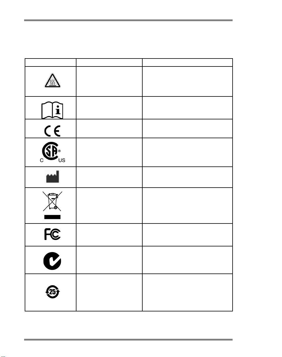
1.10 Symbols on the Rotor-Gene Q
Symbol Location Description
Near the sample
chamber, visible when
lid is open
Back of the instrument Consult instructions for use
of the instrument
of the instrument
Heat hazard —
of the chamber can reach
temperatures above 120°C
(248°F)
CE marking for European
Conformity
CSA listing mark for Canada
and the USA
1-10 Rotor-Gene Q User Manual 11/2012
of the instrument
of the instrument
of the instrument
of the instrument
of the instrument
Legal manufacturer
Waste Electrical and Electronic
Equipment (WEEE)
FCC mark of the United States
Federal Communications
Commission
C-Tick mark for Australia
(supplier identification N17965)
RoHS mark for China (the
restriction of the use of certain
hazardous substances in
electrical and electronic
equipment)

2 Introduction
Thank you for choosing the Rotor-Gene Q. We are confident
it will become an integral part of your laboratory.
Before using the Rotor-Gene Q, it is essential that you read
this user manual carefully and pay particular attention to the
safety information. The instructions and safety information in
the user manual must be followed to ensure safe operation
of the instrument and to maintain the instrument in a safe
condition.
2.1 About this user manual
This user manual provides information about the
Rotor-Gene Q in the following sections:
1. Safety Information
2. Introduction
3. General Description
4. Installation Procedures
5. Operating Procedures — Hardware
6. Operating Procedures — Software
7. Analysis User Interface
8. Additional Functions
9. Maintenance Procedures
10. Optical Temperature Verification
11. High Resolution Melt Analysis
12. Troubleshooting
13. Glossary
The appendices contain the following:
Technical data
Safety information in French and German
Mathematical techniques
Declaration of Conformity
Rotor-Gene Q accessories
Liability clause
Introduction
Rotor-Gene Q User Manual 11/2012 2-1

Introduction
2.2 General Information
2.2.1 Technical assistance
At QIAGEN we pride ourselves on the quality and availability
of our technical support. Our Technical Services Departments
are staffed by experienced scientists with extensive practical
and theoretical expertise in molecular biology and the use of
QIAGEN products. If you have any questions or experience
any difficulties regarding the Rotor-Gene Q or QIAGEN
products in general, do not hesitate to contact us.
QIAGEN customers are a major source of information
regarding advanced or specialized uses of our products. This
information is helpful to other scientists as well as to the
researchers at QIAGEN. We therefore encourage you to
contact us if you have any suggestions about product
performance or new applications and techniques.
For technical assistance and more information, call one of
the QIAGEN Technical Services Departments or local
distributors (see back cover).
For up-to-date information about the Rotor-Gene Q, visit
www.qiagen.com/RotorGeneQ.
2.2.2 Policy statement
It is the policy of QIAGEN to improve products as new
techniques and components become available. QIAGEN
reserves the right to change specifications at any time.
In an effort to produce useful and appropriate
documentation, we appreciate your comments on this user
manual. Please contact QIAGEN Technical Services.
2.2.3 Version management
This document is the Rotor-Gene Q User Manual, version 3,
for Rotor-Gene Q instruments using Rotor-Gene Q software
versions 2.1.0 or higher.
2-2 Rotor-Gene Q User Manual 11/2012

Introduction
2.3 Intended use of the Rotor-Gene Q
The Rotor-Gene Q instrument is designed to perform realtime and end-point thermal cycling using the polymerase
chain reaction (PCR) and high-resolution melting analysis
(HRM™) in molecular biology applications as well as for
other applications such as concentration measurement,
protein analysis, and enzyme kinetics.
The Rotor-Gene Q, if used in combination with QIAGEN Kits
indicated for use with the Rotor-Gene Q instrument, is
intended for the applications described in the respective
QIAGEN Kit handbooks.
If the Rotor-Gene Q instrument is used with kits other than
QIAGEN Kits, it is the user’s responsibility to validate the
performance of such product combination for any particular
application.
The Rotor-Gene Q instrument is intended for use by
professional users, such as technicians and physicians
trained in molecular biological techniques and the operation
of the Rotor-Gene Q instrument.
Rotor-Gene Q User Manual 11/2012 2-3

Introduction
This page intentionally left blank
2-4 Rotor-Gene Q User Manual 11/2012
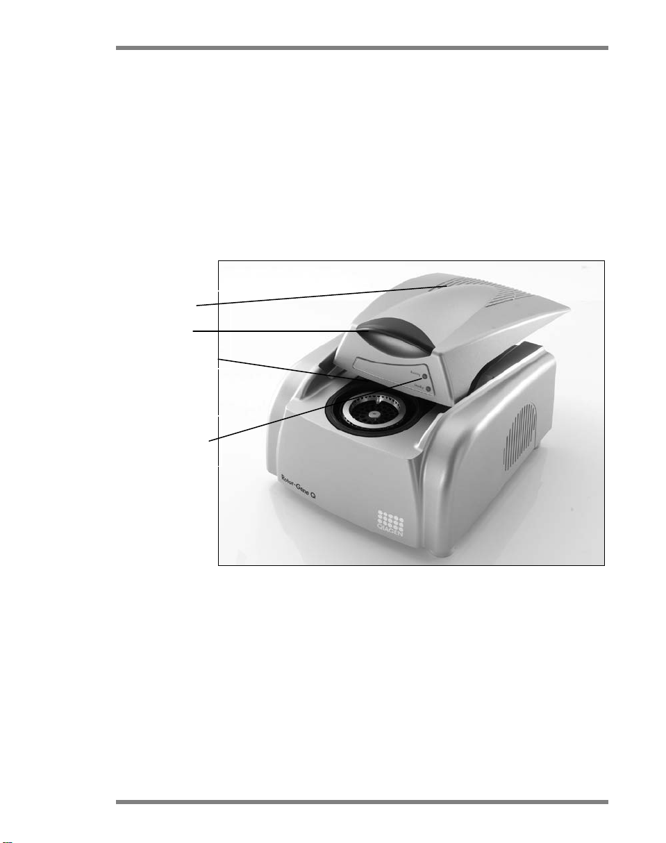
3 General Description
Rotor chamber
The Rotor-Gene Q is an innovative instrument that enables
high-precision real-time PCR, end-point PCR, and high
resolution melt (HRM) analysis. It is highly suited for use in
gene expression analysis, genotyping, pathogen detection,
and many other areas of research.
The powerful and user-friendly software provides simplicity
for beginners as well as an open experimental platform for
advanced users.
Air vents
Lid handle
Instrument
status lights
General Description
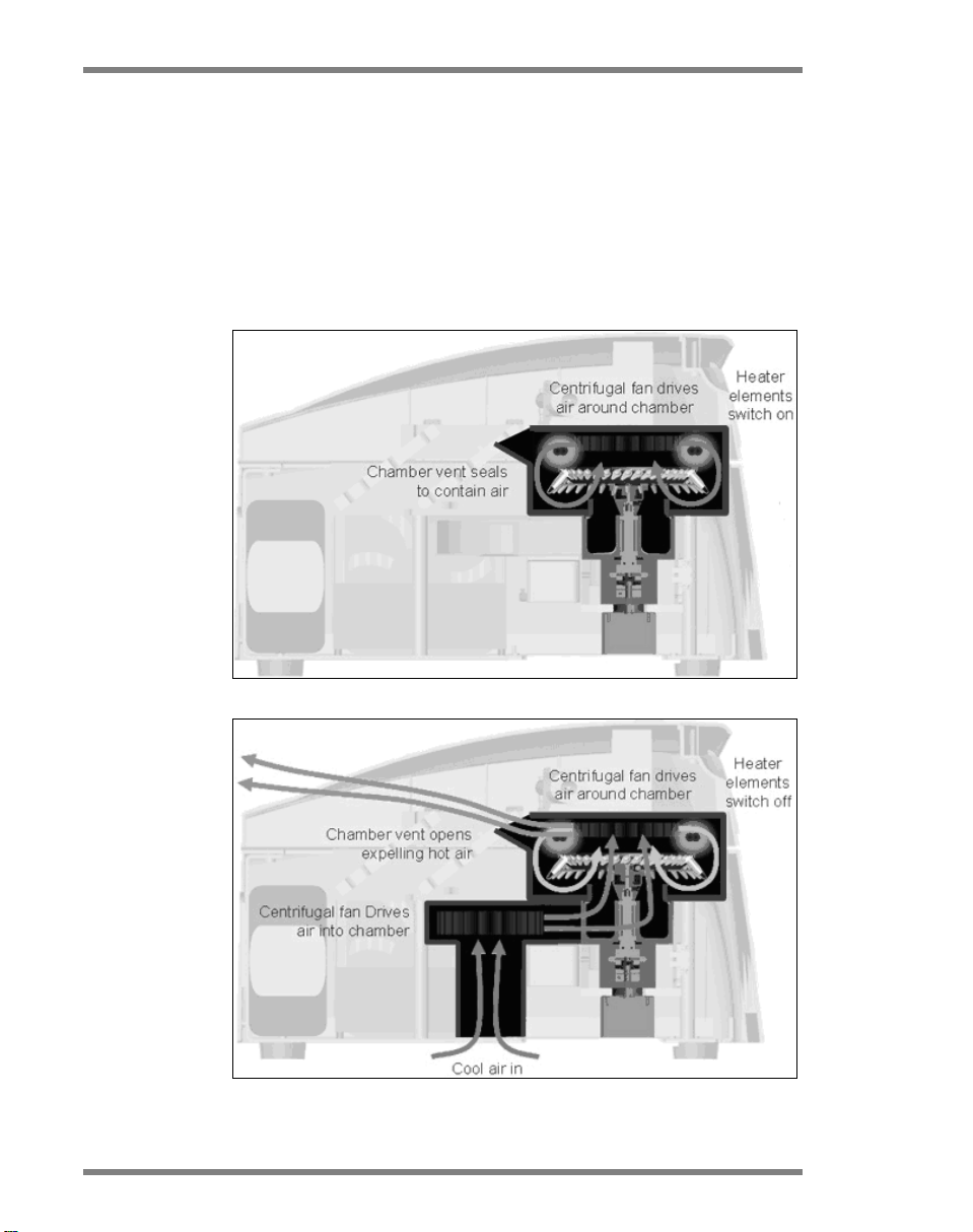
3.1 Thermal performance
The Rotor-Gene Q uses a sophisticated heating and cooling
design to achieve optimal reaction conditions. The unique
rotary format ensures optimal thermal and optical uniformity
between samples which is critical for precise and reliable
analysis.
Samples spin continually at 400 rpm during a run.
Centrifugation prevents condensation and removes air
Rotor-Gene Q User Manual 11/2012 3-1
General Description
bubbles, but does not pellet DNA. In addition, samples do
not need to be spun down prior to a run.
Samples are heated and cooled in a low-mass–air oven.
Heating is achieved by a nickel-chrome element in the lid.
The chamber is cooled by venting the air out through the top
of the chamber while ambient air is blown up through the
base.
Heating
Cooling
Illustration of the heating and cooling system.
3-2 Rotor-Gene Q User Manual 11/2012
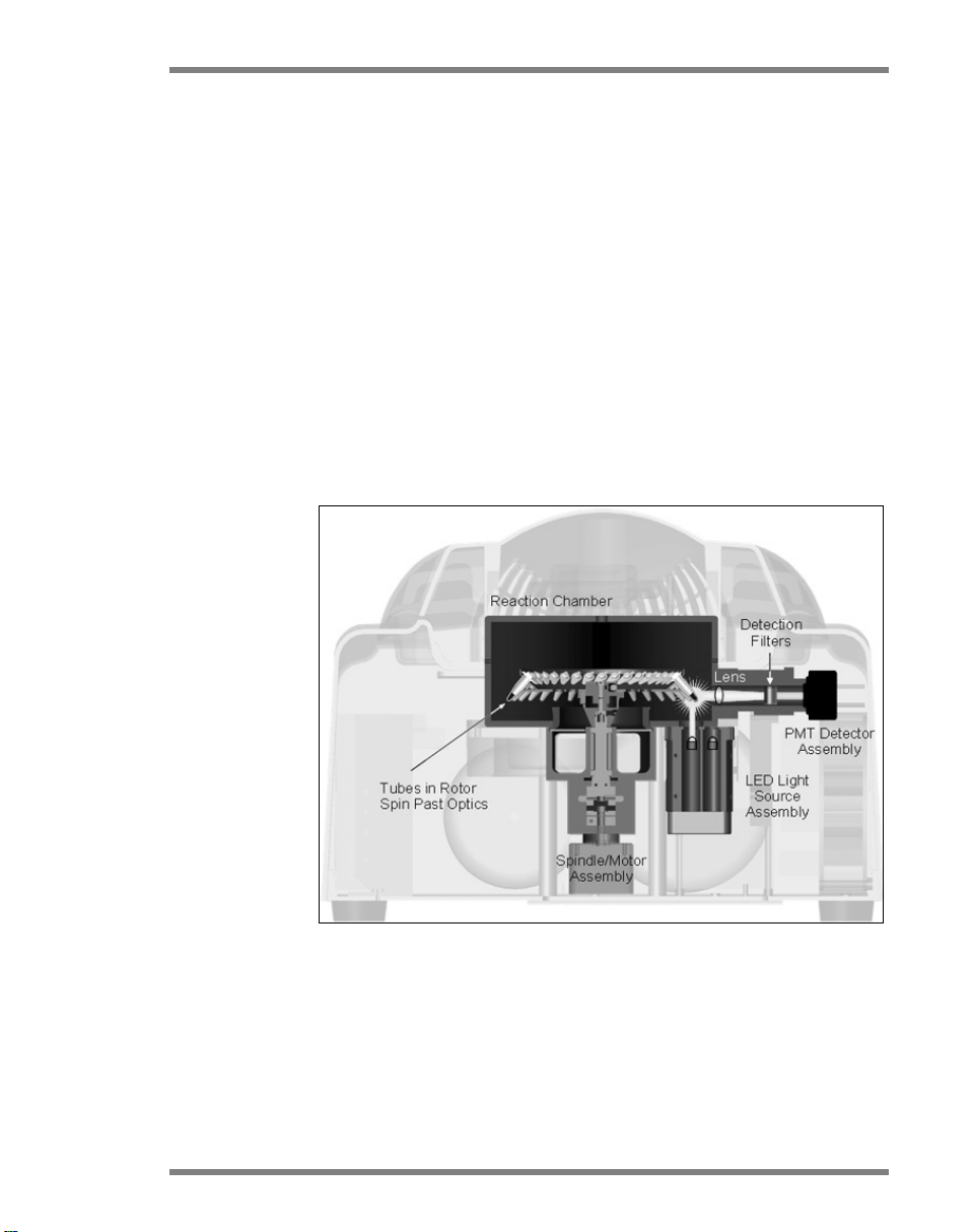
3.2 Optical system
With a choice of up to 6 excitation sources and 6 detection
filters combined with a short, fixed optical path, the
Rotor-Gene Q can be used for multiplex reactions, ensuring
minimum fluorescence variability between samples and
eliminating the need for calibration or compensation.
Samples are excited from the bottom of the chamber by a
light-emitting diode. Energy is transmitted through the thin
walls at the base of the tube. Emitted fluorescence passes
through emission filters on the side of the chamber and is
then collected by a photomultiplier. The fixed optical path
ensures consistent excitation for every sample, which means
that there is no need to use a passive internal reference dye
such as ROX.
General Description
Rotor-Gene Q User Manual 11/2012 3-3
Illustration of the optical system.

General Description
Red®, Alexa Fluor 568
Alexa Fluor 680
Available channels
Channel Excitation
(nm)
Detection
(nm)
Examples of
fluorophores
detected
®
Blue 365±20 460±20 Marina Blue
, Edans
Bothell Blue, Alexa
®
350, AMCA-X,
Fluor
ATTO 390
Green
470±10
510±5
FAM®, SYBR® Green I,
Fluorescein,
EvaGreen®, Alexa
Fluor 488
Yellow 530±5 557±5 JOE™, VIC®, HEX,
®
TET™, CAL Fluor
Gold 540, Yakima
®
Orange
585±5
610±5
Yellow
ROX™, CAL Fluor Red
610, Cy®3.5, Texas
Red 625±10 660±10 Cy5, Quasar® 670,
®
LightCycler
Red640,
Alexa Fluor 633
Crimson
680±5
712 high
pass
Quasar 705,
LightCycler Red705,
3-4 Rotor-Gene Q User Manual 11/2012
High
resolution
melt
(HRM)
460±20 510±5 SYBR Green I,
®
SYTO
9, LC Green®,
LC Green Plus+,
EvaGreen
Note: QIAGEN kits indicated for use with the Rotor-Gene Q
instruments are optimized with respect to certain dye
combinations. Please refer to the corresponding kit
handbooks, for example, the Rotor-Gene Multiplex
®
Handbook or the QuantiTect
Virus Handbook for more
information.
Installation Procedures
4 Installation Procedures
4.1 Site requirements
Rotor-Gene Q instruments must be located out of direct
sunlight, away from heat sources, and away from sources of
vibration and electrical interference. Refer to Appendix A for
the operating conditions (temperature and humidity). The
installation site should be free of excessive drafts, excessive
moisture, excessive dust, and not subject to large
temperature fluctuations.
Refer to Appendix A for the weight and dimensions of
Rotor-Gene Q instruments. Ensure that the workbench is dry,
clean, and has additional space for accessories. For further
information about required specifications of the workbench,
contact QIAGEN Technical Services.
Note: It is extremely important that the Rotor-Gene Q
instrument is placed on a stable surface, which is level and
vibration free. Refer to operating conditions — see
Appendix A.
The Rotor-Gene Q instrument must be placed within
approximately 1.5 m (59 in.) of a properly grounded
WARNING
WARNING
Rotor-Gene Q User Manual 11/2012 4-1
(earthed) AC power outlet.
Explosive atmosphere [W10]
The Rotor-Gene Q instrument is not designed for use in an
explosive atmosphere.
Risk of overheating [W16]
To ensure proper ventilation, maintain a minimum
clearance of 10 cm (3.94 in.) at the rear of the Rotor-Gene
Q instrument.
Slits and openings that ensure the ventilation of the
Rotor-Gene Q instrument must not be covered.

Installation Procedures
4.2 AC Power connection
Power requirements
The Rotor-Gene Q operates at:
100–240 V AC, 50/60 Hz; 560 VA (peak)
Make sure that the voltage rating of the Rotor-Gene Q is
compatible with the AC voltage available at the installation
site. Mains supply voltage fluctuations are not to exceed 10%
of nominal supply voltages.
Grounding requirements
To protect operating personnel, QIAGEN recommends that
the Rotor-Gene Q be correctly grounded (earthed). The
instrument is equipped with a 3-conductor AC power cord
that, when connected to an appropriate AC power outlet,
grounds (earths) the instrument. To preserve this protection
feature, do not operate the instrument from an AC power
outlet that has no ground (earth) connection.
Installation of AC power cord
Connect the suitable end of the AC power cord to the socket
located at the rear of the Rotor-Gene Q instrument, and the
other end to the AC power outlet.
4.3 PC requirements
The laptop computer, optionally supplied with the
Rotor-Gene Q, fulfills the requirements of the Rotor-Gene Q
4-2 Rotor-Gene Q User Manual 11/2012
software, detailed in the following table.

Installation Procedures
PC system requirements
Description Minimum requirement
Operating system Microsoft
®
Windows® XP
Professional edition (32 bit);
Microsoft Windows 7
Professional edition (32 bit)
Processor Intel® Core™ 2 Duo T5500
1.66 GHz or better
Main memory 1 GB RAM
Hard disk space 10 GB HDD
Graphics Adapter and screen with al
least 1200 x 800 pixels
Interface RS-232 serial port or USB
port
4.4 Unpacking the Rotor-Gene Q
The Rotor-Gene Q is delivered with all the necessary
components for setting up and running the instrument. The
box also contains a list of all the components provided.
Note: Check this list for completeness to ensure that all the
components are present.
Note: Check that the instrument and delivered accessories
are free from transport damage before installation.
The accessories box sits on top of the foam packing. The
accessories box contains:
Installation guide
CD (software)
CD (user manuals)
Loading Block 96 x 0.2 ml Tubes
Loading Block 72 x 0.1 ml Tubes
Rotor Holder (dismantled for safe transport)
36-Well Rotor (this rotor is red in color)
36-Well Rotor Locking Ring
Rotor-Gene Q User Manual 11/2012 4-3

Installation Procedures
The following items are packed on each side of the foam
packing:
USB and RS-232 serial cable
International power cable set
PCR Tubes, 0.2 ml (1000)
Strip Tubes and Caps, 0.1 ml (1000)
Once all these components have been removed from the
box, remove the foam packing on top of the Rotor-Gene Q.
Carefully remove the Rotor-Gene Q from the box and
unwrap the plastic cover. Open the lid by sliding it towards
the back to access the reaction chamber.
The following items are already installed inside the RotorGene Q:
72-Well Rotor (this rotor is blue in color)
72-Well Rotor Locking Ring
A laptop computer may be included in the packaging,
depending on your order details.
4.5 Accessories
Rotor-Discs and accessories can be ordered separately for
use with the Rotor-Gene Q. For details, see Appendix E.
4.6 Hardware installation
Once the Rotor-Gene Q has been unpacked, proceed with
CAUTION
4-4 Rotor-Gene Q User Manual 11/2012
installation as described below.
Damage to the instrument [C7]
When Rotor-Gene Q is started immediately after delivery
in cold climates, mechanical parts can block.
Allow the instrument to acclimatize to room temperature
for at least an hour before turning the instrument on.

Installation Procedures
1. Place the Rotor-Gene Q on a level and vibration-free
surface.
2. Ensure that there is sufficient space behind the instrument
for the lid to open fully.
3. Ensure that the power switch at the back of the
instrument can be reached easily.
4. Do not obstruct the back of the instrument. Ensure that
the power cord can be easily detached if required, to
disconnect power to the instrument.
5. The Rotor-Gene Q software should be installed before
the laptop computer is connected to the Rotor-Gene Q.
Please refer to Section 4.7 below, or the Rotor-Gene Q
Installation Guide provided with the instrument, on how
to install the Rotor-Gene Q software.
6. Connect the USB cable or RS-232 serial cable supplied
to a USB or communications port on the back of the
computer.
7. Connect the USB or RS-232 serial cable to the back of
the Rotor-Gene Q.
8. Connect the Rotor-Gene Q to the power supply. Connect
one end of the AC power cord to the socket located at
the rear of the Rotor-Gene Q and the other end to the
AC power outlet.
On/off switch
Power supply
port
Type plate including
serial number
Cooling fan
Serial port
USB port
Rotor-Gene Q User Manual 11/2012 4-5

Installation Procedures
Note: Only connect the Rotor-Gene Q to the computer with
the USB and serial cables delivered with the instrument. Do
not use other cables.
4.7 Software installation
1. To install the Rotor-Gene Q software, insert the CD
(software) delivered with the instrument into the CD drive
of the computer.
2. Select “Install Operating Software” in the window that
appears.
Note: For easy installation, please refer to the Rotor-Gene Q
Installation Guide provided with the instrument to guide you
through the next steps of software installation.
4-6 Rotor-Gene Q User Manual 11/2012

Installation Procedures
I
3. Once the software has been installed, a desktop icon will
be created automatically.
4. Switch on the Rotor-Gene Q by moving the toggle switch,
located at the back on the right hand side, to the “
”
position. A blue “Standby” light on the front of the RotorGene Q indicates that the instrument is ready for use.
Note: When starting connected to a computer for the
first time, the Rotor-Gene Q will be recognized by the
operating system and a number of messages will
appear. Please refer to the Rotor-Gene Q Installation
Guide provided with the instrument (CD and printed
edition) for guidance.
5. Double-click the Rotor-Gene Q Series Software desktop
icon to initiate the software.
Rotor-Gene Q User Manual 11/2012 4-7

Installation Procedures
6. A “Welcome” window appears the first time the software
is started, but does not appear for subsequent software
upgrades.
Machine Serial
Number:
Type in the serial number (7 digits), which
can be found on the back of the
Rotor-Gene Q.
Port: Choose either USB or serial cable. Select
the appropriate communications port or
click the “Auto-Detect” button.
Auto-Detect When using this option, the corresponding
USB or serial port will be detected
automatically and displayed in the “Port”
drop-down list.
4-8 Rotor-Gene Q User Manual 11/2012
Installation Procedures
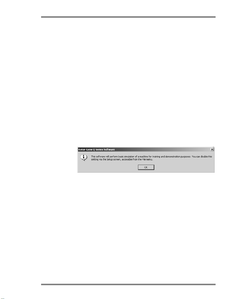
re is fully functional and can simulate
,
Run in Virtual
Mode
(for
demonstration):
Begin:
If the “Run in Virtual Mode” box is
Checking this box allows installation of the
Rotor-Gene Q software on a computer that
is not connected to a Rotor-Gene Q. The
softwa
runs.
Note: If this box is checked and a RotorGene Q is connected to the computer, the
following message appears before the run
starts: “You are about to run in Virtual
mode”. To perform a real run, the setup
must be changed in the “Setup” window
(see Section 7.5.4).
When all the information has been entered
click “Begin”. Wait until initialization is
finished, which may take a few seconds. If
virtual mode was chosen the following
message appears:
unchecked, the software initializes and
opens automatically.
Exit Program: Clicking on this button exits the program.
4.8 Software version
To find out the Rotor-Gene Q software version number, click
Rotor-Gene Q User Manual 11/2012 4-9
on “Help” then “About This Software...”.
The “About This Software…” window displays general
information about the software, including the version of the
software and the serial number and model of the instrument.

Installation Procedures
The software may be freely copied for use within an
organization that owns a Rotor-Gene Q. The software may
not be copied and distributed to others outside the
organization.
4.9 Additional software on connected
computers
Rotor-Gene Q software manages time-critical processes
during the PCR run and the data acquisition process. For this
reason, it is important to ensure that no other processes use
significant system resources and thus slow down the RotorGene Q software. It is particularly important to pay attention
to the points listed below.
System administrators are advised to consider any impact
that a modification to the system may have on the resources
before implementing it.
4-10 Rotor-Gene Q User Manual 11/2012

4.9.1 Virus scanners
We are aware of the threat that viruses cause to any
computer that exchanges data with other computers. RotorGene software is primarily installed in environments where
local policies exist to minimize this threat. These policies
usually require use of a particular anti-virus tool. Due to the
sheer number of anti-virus tools available, it is not possible
for QIAGEN to predict the possible impact on the RotorGene Q software if such a tool is active during a PCR run. In
order to get consistent results, system administrators should
therefore ensure that during performance of a PCR run:
File access is not intercepted by a virus scanner
Updates to the virus database are not performed
File scans are not performed
We strongly recommend disabling virus scanner activity
during real-time PCR data acquisition. The critical virus
scanner tasks described above can only be safely carried out
without running the risk of impacting the performance of the
instrument when the Rotor-Gene Q software is not running.
Otherwise there is a risk of adverse impact on the
performance of the instrument.
Installation Procedures
4.9.2 System tools
Many system tools may use significant system resources even
without any user interaction. Typical examples of such tools
are:
File indexing, which is performed as a background task
by many contemporary office applications
Disk defragmentation, which often also employs a
background task
Any software that checks for updates on the internet
Remote monitoring and management tools
Please be aware that due to the dynamic nature of the IT
world, this list may not be complete and tools may be
released that are not known at the time of writing. It is
important that system administrators take care that such a
tool is not active during a PCR run.
Rotor-Gene Q User Manual 11/2012 4-11

Installation Procedures
4.9.3 Operating system updates
We strongly recommend turning off any automatic update
processes of the operating system on the computer that is
used for data acquisition on the Rotor-Gene Q. We are
closely monitoring available updates and will notify
customers whenever an update is considered to be safe and
important to be installed.
4.10 Updating software
Software updates are available from the QIAGEN Web site
at www.qiagen.com/RotorGeneQ. Online registration is
necessary to download the software.
4-12 Rotor-Gene Q User Manual 11/2012

Operating Procedures — Hardware
5 Operating Procedures — Hardware
This section describes operation of the Rotor-Gene Q.
5.1 Rotor types
First, select which tube type and rotor to use. There are 4
rotors available to accommodate different tube types.
Note: 36-Well Rotor and 72-Well Rotor are delivered with
the instrument. The Rotor-Disc Rotors are accessories.
IMPORTANT: Use identical tubes in a run. Do not mix
different tube types or tubes from different manufacturers, as
this will affect optical uniformity. We recommend use of tubes
from QIAGEN which are specially designed for use with the
Rotor-Gene Q (see Appendix E). Tubes from alternative
manufacturers may autofluoresce, which could affect the
reliability of results. In addition, tubes from alternative
manufacturers can vary in length and thickness, resulting in
misalignment of the optical path of the Rotor-Gene Q and
the reaction in the tube. QIAGEN reserves the right to refuse
technical support for problems induced by non QIAGEN
certified plastic materials on the Rotor-Gene Q instrument.
IMPORTANT: Any use of non QIAGEN certified plastic
materials on the Rotor-Gene Q may void your instrument
warranty.
IMPORTANT: Visually inspect plastic consumables used on
the Rotor-Gene Q for molding imperfections or
inconsistencies. Do not use any tubes that are misshapen or
CAUTION
flawed.
Damage to the instrument [C3]
Visually inspect and make sure the rotor is not damaged or
deformed before each run.
36-Well Rotor
The 36-Well Rotor is red in color. The 36-Well Rotor and 36Well Rotor Locking Ring enable the use of 0.2 ml tubes. The
Rotor-Gene Q User Manual 11/2012 5-1

Operating Procedures — Hardware
tubes do not need to have optically clear caps because the
Rotor-Gene Q reads fluorescence from the bottom of the
tube rather than from the top. Domed capped tubes can also
be used.
72-Well Rotor
The 72-Well Rotor is blue in color. The 72-Well Rotor and
72-Well Rotor Locking Ring are used with Strip Tubes and
Caps, 0.1 ml, which can be used for volumes as low as
10 µl. The caps provide a safe and reliable seal.
Rotor-Disc 72 Rotor
The Rotor-Disc 72 Rotor is dark gray in color. The Rotor-Disc
72 Rotor and Rotor-Disc 72 Locking Ring enable use of the
Rotor-Disc 72. The Rotor-Disc 72 is a disc with 72 wells for
high-throughput use. To seal the Rotor-Disc 72, a clear
polymer film is applied to the top and heat sealed. The film
is quick to apply and prevents contamination by providing a
5-2 Rotor-Gene Q User Manual 11/2012

Operating Procedures — Hardware
strong, durable, and tamper-proof seal. For more
information on the Rotor-Disc 72, see Section 5.3.
Rotor-Disc 100 Rotor
The Rotor-Disc 100 Rotor is gold in color. The Rotor-Disc
100 Rotor and Rotor-Disc 100 Locking Ring enable use of
the Rotor-Disc 100. The Rotor-Disc 100 is a disc with 100
wells for high-throughput use. The Rotor-Disc 100 is the
rotary equivalent of a 96-well plate but with an additional 4
reference wells. It enables integration of the Rotor-Gene Q
with 96-well laboratory workflows. The extra wells can be
conveniently used for more samples, additional control
reactions, or orientation reactions, without occupying any of
the standard 96-well positions. For seamless 96-well
workflow compatibility, Rotor-Disc 100 wells use 96-well
plate labeling conventions, i.e., A1–A12 through to H1–H12.
The additional 4 reference wells are labeled R1–R4. For
more information on the Rotor-Disc 100, see Section 5.3.
Rotor-Gene Q User Manual 11/2012 5-3

Operating Procedures — Hardware
Rotor-Disc 100
30 µl
100
Rotor-Disc
15–25 µl
Rotor specifications
Well
Rotor type
capacity
Sample
no. Tube type
Recommended
reaction
volume
36-Well Rotor 200 µl 36 PCR Tubes,
72-Well Rotor 100 µl 72
Rotor-Disc 72
100 µl 72 Rotor-Disc 72 20–25 µl
Rotor
Rotor
Note: The 36-Well Rotor and 72-Well Rotor for the
Rotor-Gene Q are not to be used on Rotor-Gene 3000
instruments due to optical alignment incompatibilities. Please
continue to use the older 36-position and 72-position rotors
with Rotor-Gene 3000 instruments.
5.2 Reaction setup
IMPORTANT: Adequate controls should be used in each run
to ensure reliable results.
Reactions can be prepared using the Loading Block 96 x
0.2 ml Tubes (for PCR Tubes, 0.2 ml), the Loading Block 72 x
0.1 ml Tubes (for Strip Tubes and Caps, 0.1 ml set up with a
single-channel pipet), the Loading Block 72 x 0.1 ml Multichannel (for Strip Tubes and Caps, 0.1 ml set up with a
multichannel pipet), the Rotor-Disc 72 Loading Block (for the
Rotor-Disc 72), or the Rotor-Disc 100 Loading Block (for the
Rotor-Disc 100). All blocks are made of aluminum and can
be precooled.
20–50 µl
0.2 ml
Strip Tubes
and Caps,
10–50 µl
0.1 ml
100
5-4 Rotor-Gene Q User Manual 11/2012
The Loading Block 72 x 0.1 ml Tubes (pictured) holds 18
Strip Tubes as well as up to eight 0.5 ml tubes, which can be
used to prepare master mix, and up to sixteen 0.2 ml tubes

Operating Procedures — Hardware
which can be used to set up standard curves. The procedure
below describes reaction setup using the 72-Well Rotor. The
same procedure can be used for reaction setup using the 36Well Rotor and appropriate accessories.
1. Place the Strip Tubes into the Loading Block and aliquot
the reaction components.
2. Place the Caps securely on the Strip Tubes and visually
inspect to confirm a tight seal.
Rotor-Gene Q User Manual 11/2012 5-5

Operating Procedures — Hardware
3. Insert the Strip Tubes into the 72-Well Rotor, ensuring
that each tube sits correctly in place. Samples will not be
optimally aligned over the detection system if not placed
correctly in the rotor. This could result in a reduction in
acquired fluorescence signal and detection sensitivity. A
Rotor Holder that enables easy tube loading is provided
with the instrument.
5-6 Rotor-Gene Q User Manual 11/2012

Operating Procedures — Hardware
IMPORTANT: To achieve maximum temperature
uniformity, each position in the rotor must contain a
tube. Filling all positions in the rotor ensures even airflow
to every tube. Keep a set of empty capped tubes
available that can be used to fill any unused positions.
4. Insert the 72-Well Rotor Locking Ring onto the 72-Well
Rotor by pushing the 3 locating pins through the outer
holes of the rotor.
The Locking Ring ensures that caps remain on tubes
during a run.
Rotor-Gene Q User Manual 11/2012 5-7

Operating Procedures — Hardware
5. Insert the assembly into the Rotor-Gene Q chamber by
clicking into place using the locating pin on the rotor
hub. To remove, simply push down on the rotor hub to
release and pull out.
6. Close the lid and set up the run profile using the
Rotor-Gene Q software.
5-8 Rotor-Gene Q User Manual 11/2012

Operating Procedures — Hardware
5.3 Rotor-Disc setup
The Rotor-Disc 72 or Rotor-Disc 100 comprise 72 or 100
wells respectively in a one-piece disc designed for high
throughput. The Rotor-Disc 72 and Rotor-Disc 100 do not
use caps. Instead, Rotor-Disc Heat Sealing Film is applied to
the top and heat sealed using a Rotor-Disc Heat Sealer. The
film prevents contamination by providing a strong, durable,
and tamper-proof seal. Heat sealing the Rotor-Disc is
performed as described below.
IMPORTANT: Please read the Product Sheet supplied with
the Rotor-Disc Heat Sealer before beginning this procedure.
1. Switch on the Rotor-Disc Heat Sealer using the switch
located on the back at the right-hand side. A red
“Power” light illuminates. The Rotor-Disc Heat Sealer
takes approximately 10 minutes to reach operating
temperature, when a green “Ready” light illuminates.
Note: Once the Rotor-Disc Heat Sealer is ready, it is safe
to leave it running constantly.
2. Insert the Rotor-Disc into the Rotor-Disc Loading Block
using the position one tab on the Rotor-Disc and the tube
guide holes on the Rotor-Disc Loading Block.
3. Set up reactions in the Rotor-Disc by manual pipetting or
Rotor-Gene Q User Manual 11/2012 5-9
using the QIAgility™ automated liquid handling system.

Operating Procedures — Hardware
4. Remove the central portion from one sheet of Rotor-Disc
Heat Sealing Film by slightly folding the film in half,
pinching the center piece, and carefully tearing it out.
5. Place the film over the Rotor-Disc in the correct
orientation as shown by the “SIDE UP” label. Ensure that
the “SIDE UP” label is positioned at the bottom of the
Rotor-Disc Loading Block. The central hole in the film
should slide easily over the cylinder of the Rotor-Disc
Loading Block and onto the top of the Rotor-Disc.
6. Slide the assembly into the Rotor-Disc Heat Sealer using
the guide rails on the side of the Rotor-Disc Loading
Block. Ensure that the Rotor-Disc Loading Block is pushed
in completely.
5-10 Rotor-Gene Q User Manual 11/2012

Operating Procedures — Hardware
7. To activate the sealing mechanism, first press down on
the blue anodized bar at the top of the Heat Sealer, then
push back the black catch.
8. When the sealing mechanism has lowered, an orange
“Sealing” light illuminates. If the Rotor-Disc Loading
Block is not in the correct position, a warning beep
sounds.
Rotor-Gene Q User Manual 11/2012 5-11

Operating Procedures — Hardware
9. When sealing is finished, a beep sounds and the orange
“Ready” light illuminates. Press down on the blue
anodized bar to raise and lock the sealing mechanism
back in its original position. Do not continue sealing for
any longer than indicated by the beep or the Rotor-Disc
may deform.
10. Slide the Rotor-Disc Loading Block out of the Rotor-Disc
Heat Sealer. Allow the film to cool for approximately 10
seconds, and then gently remove the excess film.
11. Remove the Rotor-Disc from the Rotor-Disc Loading
Block.
12. Load the Rotor-Disc into the rotor using the position one
locator tab as a guide to the correct orientation.
5-12 Rotor-Gene Q User Manual 11/2012

Operating Procedures — Software
6 Operating Procedures — Software
New runs can be set up using the Quick Start wizard or the
Advanced wizard, which appear when the software is started
up. The Quick Start wizard is designed to allow the user to
start the run as rapidly as possible. The Advanced wizard
enables more options, such as configuration of Gain
Optimisation and volume settings. For convenience, the
wizards have a number of templates with default cycling
conditions and acquisition channels. To change the wizard
type, select the appropriate tab at the top of the “New Run”
window.
6.1 Quick Start wizard
The Quick Start wizard allows the user to start the run as
rapidly as possible. The user can select from a set of
commonly used templates and enter the minimum of
parameters to get started. The Quick Start wizard assumes
that the reaction volume is 25 µl. For other reaction volumes,
use the Advanced wizard (see Section 6.2).
As a first step, select the desired template for the run by
double-clicking on the template from the list in the “New
Rotor-Gene Q User Manual 11/2012 6-1
Run” window.

Operating Procedures — Software
Perform Last Run: “Perform Last Run” uses the cycling,
acquisition, and sample definitions from
the last run open in the software.
Three Step with
Melt:
This is a three-step cycling profile and a
melt curve with data acquisition on the
green channel.
Two Step: This is a two-step cycling profile with data
acquired on green, yellow, orange, and
red channels.
Quenched FRET: This is a three-step cycling profile and a
melt curve. Unlike Three Step with Melt,
acquisition is at the end of the anneal step.
6-2 Rotor-Gene Q User Manual 11/2012

Operating Procedures — Software
Nucleic Acid
Concentration
Measurement:
This is a default template for measuring
nucleic acid concentration using
intercalating dyes.
HRM: This folder contains high resolution melt
profiles.
Other Runs: This folder contains additional profiles.
The cycling and acquisition profiles for all templates can be
altered using the wizard.
Note: User-defined templates can be added to the template
list in the Quick Start wizard by copying or saving *.ret files
to C:\Program Files\Rotor-Gene Q
Software\Templates\Quick Start Templates. After
copying a file to this path, the template will appear as an
icon in the list. If you would like custom icons for your
templates, create a *.ico image with the same file name as
the template.
Subfolders can be created to group-related templates. This
allows organization of templates which could be convenient
if, for example, several users are using the same instrument.
Rotor-Gene Q User Manual 11/2012 6-3

Operating Procedures — Software
6.1.1 Rotor selection
In the next window, select the rotor type from the list.
Check the “Locking Ring Attached” checkbox and then click
“Next”.
6-4 Rotor-Gene Q User Manual 11/2012

6.1.2 Confirm profile
The cycling conditions and acquisition channels of the
template chosen are imported. These can be altered using
the “Edit Profile” window (see Section 6.2.4).
To initiate a run, click the “Start Run” button. It is also
possible to save the template before starting the run by
clicking on “Save Template”.
Operating Procedures — Software
Rotor-Gene Q User Manual 11/2012 6-5

Operating Procedures — Software
6.1.3 Save run
After clicking the “Start Run” button, the “Save As” window
appears. The run can be saved in the user’s desired location.
The run is given a file name that consists of the template
used and the date of the run. A serial number (1, 2, etc.) is
also included in the file name to allow automatic naming of
numerous runs that use the same template on the same day.
Note: The total path name should not exceed the operation
system limit of 260 characters. For example, C:\program
files\rotor-gene\experiment files\filename.rex should
not be longer than 260 characters in total.
6-6 Rotor-Gene Q User Manual 11/2012

6.1.4 Sample setup
Once the run has started, the “Edit Samples” window allows
samples to be defined and described.
Operating Procedures — Software
The “Edit Samples” window appears after the run has started
so that the user can use this time to enter sample names. For
information about setting up sample definitions in the “Edit
Samples” window, see Section 7.8.4.
6.2 Advanced wizard
The Advanced wizard enables options that are not available
in the Quick Start wizard, such as configuration of gain
optimization.
To use the Advanced wizard, select a template by doubleclicking the template name from the list under the
“Advanced” tab of the “New Run” window.
Rotor-Gene Q User Manual 11/2012 6-7

Operating Procedures — Software
Template options provided in this window are similar to
those provided when using the Quick Start wizard (Section
6.1).
Perform Last Run: “Perform Last Run” imports the cycling,
acquisition, and sample definitions from
the last run open in the software.
Empty Run: This is an empty run which allows the user
to define all parameters of the profile.
Three Step with
Melt:
This is a three-step cycling profile and a
melt curve with data acquisition on the
green channel.
6-8 Rotor-Gene Q User Manual 11/2012

Operating Procedures — Software
. For
Two Step: This is a two-step cycling profile with data
acquisition on the green channel only, to
speed up the run.
HRM: This folder contains 2 high resolution melt
profiles.
Other Runs: This folder contains additional profiles.
Instrument
Maintenance:
Note: User-defined templates can be added to the template
list by copying or saving *.ret files to C:\Program
Files\Rotor-Gene Q Software\Templates\. After copying
a file to this path, the template will appear as an icon in the
list.
This contains the template used during
Optical Temperature Verification (OTV)
more information, see Section 10. This
template is locked to ensure the profile will
always operate correctly.
6.2.1 New Run Wizard window 1
In the next window, select the rotor type from the list.
Check the “Locking Ring Attached” checkbox and click
“Next” to proceed.
Rotor-Gene Q User Manual 11/2012 6-9

Operating Procedures — Software
6.2.2 New Run Wizard window 2
In the next window, the user’s name and notes about the run
can be entered. The reaction volume must also be entered.
If the 72-Well Rotor was selected in window 1, three “Sample
Layout” options are available in the drop-down menu. “1, 2,
3...” is the default option. Most users select this option. “1A,
1B, 1C...” should be selected when samples were loaded in
adjacent 0.1 ml Strip Tubes using a multichannel pipet with 8
channels. The “A1, A2, A3...” layout may be selected if
appropriate.
6-10 Rotor-Gene Q User Manual 11/2012

Operating Procedures — Software
6.2.3 New Run Wizard window 3
In this window, the “Temperature Profile” and “Channel
Setup” can be modified. If the “Edit Profile...” button is
clicked, the “Edit Profile” window appears, enabling
alteration of cycling conditions and selection of acquisition
channels (Section 6.2.4).
After setting up the profile, click the “Gain Optimisation...”
button to bring up the “Gain Optimisation” window (see
page 6-24).
Rotor-Gene Q User Manual 11/2012 6-11

Operating Procedures — Software
allows addition of a new cycle after the
6.2.4 Edit Profile
The “Edit Profile” window allows the cycling conditions and
acquisition channels to be specified. The initial profile shown
is based on the template selected when setting up the run
(see page 6-1). The profile is displayed graphically. The list
of the segments of the profile appears below the graphical
display. This list can include Hold (page 6-13), Cycling (page
6-14), Melt (page 6-17), or HRM if the instrument has a HRM
channel (page 6-18).
Each stage of the profile can be edited by clicking on the
appropriate area of the graphical display or on the name in
the list, and then changing the settings which appear.
Insert after...:
Insert before...: This allows addition of a new cycle before
Remove: This removes the selected cycle from the
This
selected cycle.
the selected cycle.
profile.
6-12 Rotor-Gene Q User Manual 11/2012

Operating Procedures — Software
Hold
A Hold instructs the Rotor-Gene Q to remain at the
designated temperature for a set time. To change the
temperature, click on the “Hold Temperature” button and
type or use the slide bar to select the desired temperature. To
change the duration of the Hold, click on the “Hold Time”,
“mins”, and “secs” buttons.
If performing Optical Denature Cycling, a Hold can be used
as a calibration step. In this case, a calibration melt is
performed before the Hold. By default, this is configured for
the first Hold in the run, but may be changed if required.
Rotor-Gene Q User Manual 11/2012 6-13

Operating Procedures — Software
For more information about Optical Denature Cycling, see
page 6-18.
Cycling
Cycling repeats the user-defined temperature and time steps
a specified number of times. The number of repeats is set
using the “This cycle repeats X time(s).” button.
A single cycle is displayed graphically (as shown in the
screenshot, below). Each step of the cycle can be altered. The
temperature can be changed by dragging the temperature
line in the graph up or down. The duration of the step can be
changed by dragging the temperature boundary in the graph
left or right. Alternatively, click on the step and use the
temperature and time buttons to the left of the graph.
6-14 Rotor-Gene Q User Manual 11/2012

Operating Procedures — Software
Steps can be added or removed from the cycle using the “-“
and “+” buttons at the top right of the graph.
Long Range: Checking this box increases the hold time
of the selected step by one second with
each new cycle.
Touchdown: Checking this box decreases the
temperature by a specified number of
degrees for a specified number of initial
cycles. This is then shown in the display.
Acquisition
Data can be acquired on any channel at any cycling step. To
set a channel to acquire data, click on the “Not Acquiring”
button (if a channel has already been set to acquire at this
step, then the acquiring channels are listed here).
Rotor-Gene Q User Manual 11/2012 6-15

Operating Procedures — Software
After clicking the “Not Acquiring” button, the “Acquisition”
window appears.
To set a channel to acquire, select the channel and move it
from the “Available Channels” list to the “Acquiring
Channels” list using the
button. To remove a selected
6-16 Rotor-Gene Q User Manual 11/2012

Operating Procedures — Software
channel from the “Acquiring Channels” list, use the
button. The
“Acquiring Channels” list. Clicking the “Don't Acquire” button
also removes all acquisitions from the step.
If more than one cycling sequence is included in the profile,
the acquired data can be appended to the data acquired
from the earlier cycling. Use the “Same as Previous” dropdown menu to select the cycling step to which the data
should be appended.
The Dye Channel Selection Chart helps the user to decide
which channel is appropriate for dye they intend to use. The
dyes shown in the table are those that are commonly used,
and do not indicate the limits of the instrument.
The acquisition options described above also apply to “Melt”
steps, except that it is not possible to append acquisition data
using the “Same as Previous” menu.
button removes all the channels from the
Melt and hybridisation
A Melt is a ramp between 2 temperatures, from a lower to a
higher temperature. The permitted temperature range is
35–99ºC.
To set up a Melt, specify the start temperature, the end
temperature, the temperature increments, the length of time
to hold at the first acquisition temperature before the ramp is
initiated, the time each increment is to be held for, and the
acquisition channels.
A ramp will be generated between the 2 temperatures. If the
start temperature is higher than the end temperature, the
name of the step will change to “Hybridisation”. The
“Acquiring To” option, set to Melt A in the screenshot below,
can be changed by clicking the button. The “Acquisition”
Rotor-Gene Q User Manual 11/2012 6-17
window will appear and the channels can be selected.

Operating Procedures — Software
When running a standard melt the temperature is increased
by increments of 1ºC, waiting for 5 seconds before each
acquisition. The Rotor-Gene Q can be configured to perform
melts in 0.02ºC increments. The minimum hold time
between temperature steps varies depending on the number
of degrees between each step.
High Resolution Melt
High resolution melt (HRM) analysis characterizes doublestranded DNA samples based on their dissociation (melting)
behavior. It is similar to classical melting curve analysis, but
provides far more information for a wider range of
applications. Samples can be discriminated according to
sequence, length, GC content, or strand complementarity,
down to single base-pair changes.
HRM analysis can only be performed on instruments that
have HRM hardware and software installed. Data is acquired
using specialized HRM sources and detectors. HRM analysis
also includes the option to perform Gain Optimisation just
before the Melt begins. After performing HRM, the data can
be analyzed with HRM analysis software (Section 11).
Optical Denature Cycling
Optical Denature Cycling is an exciting technique, available
on the Rotor-Gene Q, which performs real-time melt analysis
to determine the melt peak of a reference sample. This
indicates PCR product denaturation with higher precision
than setting a particular denature temperature for a hold
time. To perform this technique, simply place a reference
tube of PCR product in tube position 1 of the rotor. The
6-18 Rotor-Gene Q User Manual 11/2012
Operating Procedures — Software
reference tube must also contain a detection chemistry that
enables detection of strand dissociation.
When heating to the initial denature temperature, a melt is
performed on the green channel from 80ºC to 95ºC, by
default. The parameters of this initial melt can be adjusted by
the user. From this data, a melt curve is generated and
automatically analyzed.
The melt peak is referenced back to the raw data to obtain a
denature threshold. Then, every Optical Denature Cycling
step, the instrument is heated as quickly as possible and data
is acquired continually. Once the reference tube has reached
the denature threshold fluorescence level, the instrument is
immediately cooled and proceeds to the next programmed
step in the cycle. A peak is not calculated while cycling.
Instead, the fluorescence level is referenced to the melt peak
and this designates the denature threshold.
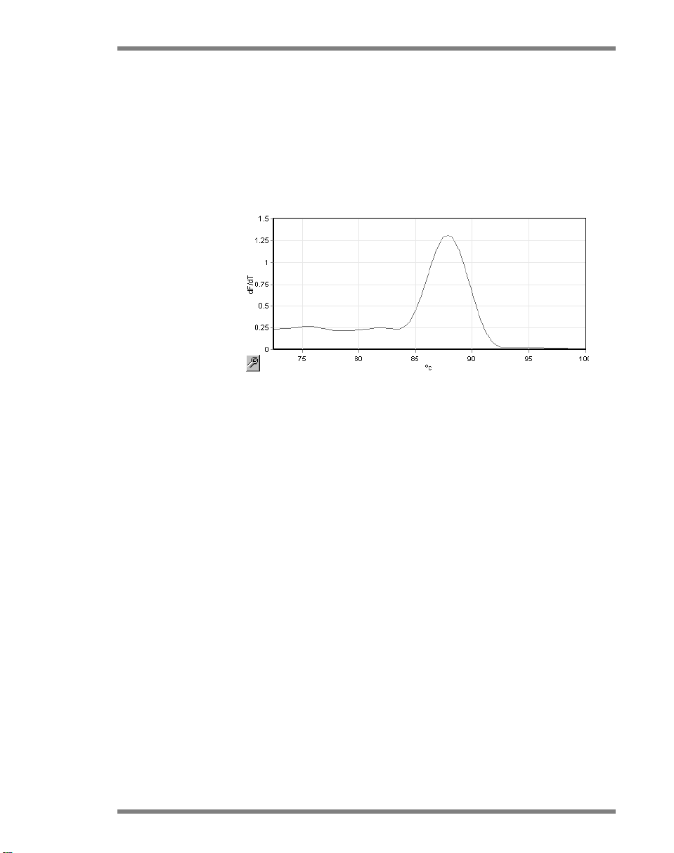
In the following graph, the raw fluorescence readings and
the first derivative have been overlaid. This shows the
correspondence between the denature threshold and the
melt peak obtained during the calibration.
Rotor-Gene Q User Manual 11/2012 6-19

Operating Procedures — Software
To perform Optical Denature Cycling, you will need:
A preamplified PCR product to place in position 1 of the
rotor. This sample should contain the same PCR product
as the samples of interest and a detection chemistry for
monitoring PCR product dissociation.
An optical denature profile. A new profile can be created
or an existing profile can be edited (see details below).
An Optical Denature Cycle appears almost identical to other
cycles. The principal differences are the melt step
automatically inserted at the beginning of the profile, and the
sharp profile of the denature step during cycling. The Optical
Denature Cycle does not require defined hold times as the
dissociation of the product is monitored at each cycle.
To perform this technique, the following information about
the run is required:
The initial denaturation temperature. This is the same
temperature as the Denature step in a standard cycling
profile.
The tube position of the PCR sample that will produce a
melt curve on the green channel.
An Optical Denature Cycling profile must be defined.
Create a new Optical Denature Cycle as follows.
1. Open the “Edit Profile” window. Then click on “New”. In
the window that appears, click the “Insert after” button
6-20 Rotor-Gene Q User Manual 11/2012

Operating Procedures — Software
and select “New Cycling” from the menu. Select one of
the temperature steps by clicking on the graph. In the
drop-down menu, change from “Timed Step” to “Optical
Denature”. A default profile containing a Denature step
and an Optical Denature Cycle step will appear.
The ramped region at the beginning of the run
represents the calibration process. The green dots
represent the acquisitions taken each cycle during
heating. The blue dots represent the acquisition at the
end of the anneal step at 60ºC. Note that while the
profile shows each step with the same denature
temperature, this may not be the case. If the sample
requires slightly longer to melt towards the end of the
run, the optical denature process waits for the melt
according to the fluorescent data, and not according to
time. For this reason, the temperature trace may vary for
each cycle.
2. Click on the first half of the graph with the Optical
Denature symbol
. The “Calibration Settings”
information appears on the left of the screen.
3. The “Calibration Settings” information is usually correct.
To modify it, if necessary, click “Edit”. The “Calibration
Settings” window appears.
Rotor-Gene Q User Manual 11/2012 6-21

Operating Procedures — Software
4. Ensure that:
The tube indicated in “Tube Position” contains a PCR
product that will show a melt peak on the green
channel.
The final ramp temperature will not burn the sample,
yet will be high enough to allow it to melt.
The hold time is sufficient to denature the sample.
The denature offset is set appropriately. The default
o
C is appropriate for most melts. Melts with very
of 0
sharp transitions may require a denature offset of
o
C to –2oC, as determined by the user, to ensure
–0.5
that melt transition is detected.
You can also define a Denature step by introducing a new
Hold step. Click on “Insert before” and select “New Hold at
Temperature” from the menu. The calibration settings will
appear.
6-22 Rotor-Gene Q User Manual 11/2012

Operating Procedures — Software
The calibration settings are synchronized with the denature
settings, so a change to the hold time in the Denature step
will automatically update the calibration hold time. This is
because the calibration process and denaturation are
equivalent in Optical Denature Cycling.
Changing an existing step to use Optical Denature Cycling
To change an existing Denature step in a cycling sequence,
select the cycle in the list in the “Edit Profile” window. Then,
select the Denature step by clicking on it in the display.
Click on the drop-down menu and select "Optical Denature".
The temperature and hold time are removed and the
“Optical Denature” icon
is displayed.
Rotor-Gene Q User Manual 11/2012 6-23

Operating Procedures — Software
Gain Optimisation
When setting up a new run, it is helpful to use the “Gain
Optimisation” function. This allows you to optimize the gain
to a setting that will provide the desired range of starting
fluorescence at a set temperature (usually the temperature at
which data acquisition occurs) in each of the channels being
acquired. The aim of Gain Optimisation is to ensure that all
data is collected within the dynamic range of the detector. If
the gain is too low, the signal will be lost in background
noise. If it is too high, all signal will be lost off scale
(saturated).
The gain range for each channel is –10 to 10, where –10 is
the least sensitive and 10 is the most sensitive.
When running reactions for the first time, we recommend
preparing a test sample containing all the reaction
components. Place the test sample in the Rotor-Gene Q and
use Gain Optimisation to determine the best gain setting. If
the gain chosen by Gain Optimisation results in a poor
signal then the “Target Sample Range” should be increased.
If it results in a signal that is saturated then the “Target
Sample Range” should be decreased.
To perform Gain Optimisation, click on the ”Gain
Optimisation…” button in New Run Wizard window 3 (see
6-24 Rotor-Gene Q User Manual 11/2012
Section 6.2.3).

Operating Procedures — Software
The “Auto-Gain Optimisation Setup” window appears. This
window enables optimization by automatically adjusting the
gain settings until the readings for all selected channels fall
within or below a certain threshold.
Rotor-Gene Q User Manual 11/2012 6-25

Operating Procedures — Software
Set temperature
to:
Before reading, the Rotor-Gene Q will be
heated or cooled to match the specified
temperature. By default, this is set as the
acquisition temperature.
Optimise
All/Optimise
Acquiring:
“Optimise All” will attempt to optimize all
channels known by the software. “Optimise
Acquiring” will only optimize the channels
that are used in the thermal profile defined
in the run (cycling and melt).
Perform
Optimisation
Before 1st
Acquisition:
Check this box to perform Gain
Optimisation at the first cycle in which data
acquisition occurs. This is recommended
for Auto-Gain Optimisation.
6-26 Rotor-Gene Q User Manual 11/2012

Operating Procedures — Software
ation is
10 and 10 that gives
Perform
Optimisation At
[x] Degrees At
Beginning of
Run:
Channel
Settings:
Edit...:
Check this box to perform Gain
Optimisation just before starting the run.
The Rotor-Gene Q is heated to the
specified temperature, Gain Optimis
performed, and then cycling begins on the
first step, usually a Denature step. This
option may be chosen if a Gain
Optimisation during the run would result in
too much time spent on the initial step.
Usually “Perform Optimisation Before 1st
Acquisition” is preferred because Gain
Optimisation is performed as close as
possible to the run conditions.
This drop-down menu allows channels to
be added. Choose the channel of interest
and click “Add”.
This opens a window in which the “Target
Sample Range” can be set. The “Target
Sample Range” is the range of initial
fluorescence that should be set for the
sample in the specified tube. Auto-Gain
Optimisation reads each channel using
gain settings in the range specified by
“Acceptable Gain Range”. It chooses the
first gain setting that results in a
fluorescence reading within the “Target
Sample Range”. In the example shown,
Auto-Gain Optimisation searches for a
gain setting between –
a reading between 5 and 10 FI in tube 1.
In general, for intercalating dyes a “Target
Sample Range” of 1–3 FI is appropriate,
while a range of 5–10 FI is more suitable
for probe chemistries.
Rotor-Gene Q User Manual 11/2012 6-27

Operating Procedures — Software
ation. A gain is
n changed.
Remove/
Remove All:
“Remove” removes the highlighted
channel. “Remove All” removes all
channels.
Start:
“Start” begins Gain Optimis
chosen which results in fluorescence signal
levels within the specified range. If
fluorescence falls outside the specified
range, the gain is set to give the closest
match possible.
Manual: This opens the “Manual Gain Adjustment”
window (see page 6-29).
Changing Gain
During a Run:
If the gain at the beginning of the run was
too high or too low, it can be changed
within the first ten cycles. A vertical line
appears where the gain has bee
The cycles before the change are excluded
from the analysis.
Note: Gain Optimisation may chose a setting which does
not fall within the specified range. This can be due to
changes in fluorescence after the first Hold step. However,
the result of Gain Optimisation provides a good indication of
the fluorescence level the run will be started on.
6-28 Rotor-Gene Q User Manual 11/2012

Operating Procedures — Software
Manual Gain Adjustment
To perform “Manual Gain Adjustment”, click on “Manual…”
in the “Auto-Gain Optimisation Setup” window. The “Manual
Gain Adjustment” window appears. This window displays the
fluorescent readings at any given temperature in real-time. It
is used when the background of a sample is unknown and
therefore the gain must be determined to ensure the sample
signal is sufficient for detection.
By default, all samples are shown in the display. Samples
can be removed from or added to the display using the
toggler to the right. The toggler consists of colored cells,
each of which corresponds to a sample in the display.
Samples with a brightly colored cell are displayed, while
samples with a faded cell are not displayed. Samples can be
switched on or off by clicking on the cell or by dragging the
mouse pointer across several cells at time.
We recommend performing Manual Gain Adjustment as
follows.
1. Adjust the temperature in the “Manual Gain Adjustment”
window to the acquisition temperature required for the
run.
Rotor-Gene Q User Manual 11/2012 6-29

Operating Procedures — Software
Note: The temperature will not be adjusted while the
Rotor-Gene Q is operating. Restart the Rotor-Gene Q to
apply changes made to the temperature.
2. Click on “Start”. The run begins. The Rotor-Gene Q
temperature is adjusted to the temperature specified in
the window. The graphs in the window start to display
data.
3. Wait for the temperature to stabilize.
4. Note the end point fluorescence (Fl) reading.
5. If the Fl reading is not at the required level, click on “Edit
Gains…” and edit as required. This process may not be
instantaneous, as the Rotor-Gene Q takes ~4 seconds to
acquire each point in each channel, and during this time
the user interface is deactivated.
6. Repeat the process until the FI is at the desired level.
7. Click on “Stop”. If the run is still acquiring data when the
“Stop” button is clicked, the Rotor-Gene Q finishes
acquiring first, and then stops. This process can take up
to 5 seconds for each acquiring channel.
6-30 Rotor-Gene Q User Manual 11/2012

Operating Procedures — Software
6.2.5 New Run Wizard window 4
This window summarizes the run. Check the parameters and
if they are correct, click “Start Run”. You will be prompted
for a file name. You can also save the run settings as a
template for future runs using the “Save Template” button.
6.2.6 New Run Wizard window 5
Enter sample types and descriptions in this window while the
run is in progress. The functionality of this window is identical
to the “Edit Samples” window (page 7-70). Sample
information may also be entered after the run has finished.
The “Finish and Lock Samples button” closes the screen and
prevents the sample names from being modified. For more
information about this and other security features, see
Security menu (Section 7.9).
Rotor-Gene Q User Manual 11/2012 6-31

Operating Procedures — Software
6-32 Rotor-Gene Q User Manual 11/2012

Analysis User Interface
7 Analysis User Interface
This chapter describes the Rotor-Gene Q software user
interface.
7.1 Workspace
The workspace is the backdrop of the main window. In this
area, raw data plots and analysis results can be opened. If
several windows are opened simultaneously, they can be
organized by clicking the “Arrange” button on the toolbar.
There are several window arrangement options available
that can be selected by clicking on the down arrow next to
the “Arrange” button.
7.2 Toolbar
These buttons are shortcuts to frequently used operations.
These operations can also be accessed from the drop-down
menus.
7.3 View raw channels
Click on these buttons to view the raw (unanalyzed) data
Rotor-Gene Q User Manual 11/2012 7-1
from particular channels in the run.

Analysis User Interface
up a window
When viewing this data, a number of options are available to
change the data presentation. The raw data may also be
transformed to facilitate different types of analysis.
Adjust Scale:
To select “Adjust Scale”, click the right
mouse button over the appropriate
window. “Adjust Scale” brings
in which a scale can be specified.
Autoscale: “Autoscale” attempts to fit the scale to the
maximum and minimum readings of the
data.
Default Scale: “Default Scale” resets the scale to display
from 0 to 100 fluorescence units.
Spanner/wrench
See Section 8.5 for more information.
icon:
Options: This displays the drop-down menu shown
above, which provides options for
transformation of the raw data.
Normalise to ...:
This enables normalization of amplification
data to data from a passive reference dye,
such as ROX, acquired in another channel.
7-2 Rotor-Gene Q User Manual 11/2012

Analysis User Interface
Crop start cycles: This creates a new channel data set in
which some start cycles have been
removed. This is useful if large jumps are
observed in the initial cycles, which can
occur when using certain chemistries.
Crop end cycles: This creates a new channel data set in
which some end cycles have been
removed.
Page 1: This indicates the page that is currently
selected to display the raw data plots. The
“Edit Sample” window allows the creation
of multiple sample definitions. For
example, data can be viewed with varying
line thickness, sample definitions, and
other display options. This is particularly
useful if relative quantitation is performed
in a single channel, because the user can
easily switch the view between the gene of
interest and housekeeper samples by
defining 2 sample pages.
7.4 Toggling samples
At the right-hand side of the main window is a toggler, which
includes a sample legend. This consists of colored cells, each
of which corresponds to a sample in the display. The toggler
is used to control which samples can be seen in the display.
Samples with a brightly colored cell are displayed while
samples with a faded cell are not displayed. Samples can be
switched on or off by clicking on the cell or by dragging the
mouse pointer across several cells at time. The “Bank On”
and “Bank Off” buttons hide or display, respectively, all
samples currently visible in the list. The scroll bar can be
used to display the next group of samples.
Note: The number of displayed samples is dynamic, and
depends on the space available in the window.
Rotor-Gene Q User Manual 11/2012 7-3

Analysis User Interface
Clicking “Named On” shows only those samples that have
been given a name. This is a quick way to show only relevant
samples. Clicking “All On” or “All Off” displays all or none
of the samples in the rotor respectively. Pressing the “Edit
Samples…” button opens the “Edit Samples” window where
sample names, types, and standard concentrations can be
edited (see Section 7.8.4).
The toggler is shown below. The additional options displayed
appear after clicking the right-mouse button over the toggler.
7-4 Rotor-Gene Q User Manual 11/2012

Analysis User Interface
indicates
channel and generate independent reports.
Empty
or
Page: This label at the top of the toggler
the sample page that is displayed. Pages
allow varied independent analyses from
one channel data set. For example, you
can run two standard curves in the green
More information on setting up sample
pages is available in Section
7.8.4.
Toggle Sample
ID Display:
Select NonSamples:
Select Groups:
7.5 File menu
If a 72-Well Rotor is used, samples are
shown in the format A1 to A8, B1 to B8,
etc. The “Toggle Sample ID Display” option
allows the user to switch to a numerical
sample order (1 to 72).
This option deselects any samples that have
a “Type” specified as "None" in the “Edit
Samples” window. This ensures that only
samples relevant for the analysis are
displayed.
If you have defined groups, this feature will
toggle (switch on/off) the display of the
samples in the groups. Groups are
arbitrary collections of samples that allow
advanced reporting of statistical results. F
example, groups of treated and untreated
patient samples can be defined. Groups
can be set up in the “Edit Samples”
window.
7.5.1 New
After selecting “File” and then “New”, the “New Run” window
appears. This window provides commonly used templates
organized under “Quick Start” and “Advanced” tabs. Once
the template is selected, the wizard guides you through the
Rotor-Gene Q User Manual 11/2012 7-5
run setup and allows modification of settings and profiles.

Analysis User Interface
For information about the templates provided, see Section
6.1 and Section 6.2.
New Run
New...: This initiates the run setup using the
selected template.
Cancel: This closes this window.
Help: This opens the online help.
Show This Screen
When Software
Opens:
If this box is checked, the “New Run”
window is displayed when the software is
started.
7-6 Rotor-Gene Q User Manual 11/2012

7.5.2 Open and Save
Use this function to save the run file or data
Open...: This opens a previously saved Rotor-Gene
Q run file (*.rex) or Rotor-Gene Q run
archive (*.rea file).
Open Recent...: This displays the last 4 files that have been
opened or saved.
Save: This saves any changes that have been
made to a run file.
Analysis User Interface
Save As...:
Run File...: This saves a copy of the file. The user can
Template...: This saves the profile setup and associated
Rotor-Gene Q User Manual 11/2012 7-7
in various formats. The options are listed
below.
change the name and the save location.
This is the default format.
settings but not the run data. The template
can be used to initiate future runs.

Analysis User Interface
tact QIAGEN Technical
are
Run Archive...: This saves in a more compact file format.
Save files in this format before they are emailed. This reduces the time required to
send the file and ensures that files are not
corrupted by e-mail clients.
LIMS Export
This saves the analysis in LIMS compatible
formats according to the requirements of
the user. Please con
Services for more information.
Excel Data
Sheet...:
This exports all the raw channels to an
®
sheet. Only the selected samples
Excel
exported.
Excel Analysis
Sheet...:
LinReg Export
Format...:
This exports all the analysis in the current
run into a single Excel sheet.
This exports all raw channel data into a
format that can be read by LinReg (an
efficiency analysis tool). See “Exporting To
LinReg” below for more details.
Matlab Export...: This exports the data into a format that can
be read by the scientific package Matlab
(or its open-source equivalent, Octave).
This may be useful for methods research.
Exporting To LinReg
LinReg is a tool developed by C. Ramakers and coworkers.*
The LinReg tool is available from: http://LinRegPCR.nl.
Rotor-Gene Q software allows the user to export raw data in
a format that can then be imported by the LinReg tool for
analysis.
1. Open the Rotor-Gene Q run file containing the raw data.
* Ramakers, C., Ruijter, J.M., Deprez, R.H., and Moorman, A.F. (2003)
Assumption-free analysis of quantitative real-time polymerase chain reaction
(PCR) data. Neurosci. Lett. 339, 62.
7-8 Rotor-Gene Q User Manual 11/2012

2. Export the data to the LinReg export format by selecting
“Save As…” and then “LinReg Export Format…”.
3. Microsoft Excel automatically displays the exported raw
data.
4. Start up the LinReg tool.
5. The tool asks you to select the cell range where the raw
data is located. The tool can only analyze one raw
channel at a time, so an appropriate region of the Excel
sheet should be selected.
7.5.3 Reports
After selecting “Reports”, the “Report Browser” window
appears. If the data has already been analyzed, the report of
that analysis can be displayed from the “Report Browser”
window. Several report types are offered with varying
degrees of detail.
Analysis User Interface
7.5.4 Setup
The initial setup of the Rotor-Gene Q should be completed
during installation. However, this option allows you to
change the Rotor-Gene Q connection setup, if you wish to do
so after installation.
Rotor-Gene Q User Manual 11/2012 7-9

Analysis User Interface
mode is useful for demonstration purposes,
. If you are
Virtual Mode:
Select this option if the software will be
used without a connected Rotor-Gene Q.
The software retains all functions. This
data analysis, and setting up templates.
Allow access to
this setup screen:
If this option is not checked during setup,
this window can no longer be accessed.
This security measure prevents users from
altering the settings. To reestablish access,
contact your distributor.
Port:
Select the correct communication port to
enable communications between the
computer and the Rotor-Gene Q
unsure which port to select, click “AutoDetect” to search for all available ports.
Auto-Detect If you are unsure which port to select, click
“Auto-Detect” to search for all available
ports.
7-10 Rotor-Gene Q User Manual 11/2012

7.6 Analysis menu
7.6.1 Analysis
After clicking “Analysis”, the “Analysis” window appears. This
window allows creation of new analyses and display of
existing analyses. The method of analysis is selected using
the tabs. A list of the channels that can be analyzed using the
selected method is shown. Multiple assays run in the same
channel can be analyzed independently, provided they have
been set up as separate pages in the “Edit Samples” window.
Pages that have already been analyzed have a green
checkmark next to them. This means that threshold and
normalization settings have been saved for this analysis. To
view or analyze a channel, double-click on it. The specific
analysis window appears.
Analysis User Interface
Auto-shrink
window:
Rotor-Gene Q User Manual 11/2012 7-11
Selecting “Auto-shrink window” shrinks the
window when it is not in use. Moving the
cursor over the window enlarges the
window again.

Analysis User Interface
or melt bins set up in
Organizing the workspace
Each time a new analysis is started, its windows are arranged
to fit in with those already on the screen. If many windows
are displayed, this can be cumbersome. Close the windows
you do not require, then click “Arrange” on the toolbar. The
windows are automatically arranged according to the “Smart
Tiling” method. Alternatively, select another arrangement
method by clicking the arrow next to the “Arrange” button.
Clicking the right mouse button on the name of an analysis
also provides additional options.
Show: This displays the selected analysis.
Hide: This hides the selected analysis.
Remove
Analysis…:
7.6.2 Quantitation
Select the “Quantitation” tab in the “Analysis” window and
then double click on the channel name or select the channel
and then press the “Show” button to open the channel of
interest. Three windows appear: the main screen, the
standard curve, and the results.
This removes the selected analysis
completely. This means that any
normalization settings
the analysis will be lost.
7-12 Rotor-Gene Q User Manual 11/2012

Analysis User Interface
of the “Preview” window
Reports
Reports: “Reports” opens the “Report Browser”
window where a report of the current
analysis can be generated. There are 3
options: standard report, full report, and
concise report. Double-click on the desired
option to open the report in the “Preview”
window.
After the report has been generated, the
buttons on the top
can be used to print, save, or e-mail the
report, or export it to Word.
Standard Curve
Std. Curve: This button opens the “Standard Curve”
window. By default, this window is opened
when an analysis is opened. If you close
the window, it can be reopened using this
command.
Rotor-Gene Q User Manual 11/2012 7-13

Analysis User Interface
If redefining standards to recalculate
The values on the standard curve are
Efficiency: This is the reaction efficiency of the run.
recalculated dynamically as the threshold
level is varied by clicking and dragging the
threshold line in the main window.
Blue dots on the curve represent the
samples that have been defined as
standards and red dots represent the
unknown sample data points.
Note:
the standard curve, toggling the standard
sample visibility to off using the toggler on
the right of the screen will remove it from
the standard curve calculation. Removing
standards from the graph to increase the
R^2 value is not scientifically valid. A
failed standard is an indication that the
samples may also have failed, and so
should be included in the results.
This value is discussed in more detail on
page 7-28.
7-14 Rotor-Gene Q User Manual 11/2012

Analysis User Interface
the calculated concentrations) may not
ave been
accurate indication of the reliability of
standard curve are automatically calculated
ption to export
R^2 value
(correlation
coefficient):
R value (square
root of
correlation
coefficient):
M and B:
The R^2 value, or R2 value is the
percentage of the data that is consistent
with the hypothesis that the standards form
2
a standard curve. If the R
value is low,
then the standards do not easily fit onto a
line of best fit. This means that the results
(i.e.,
be reliable. A good R2 value is
approximately 0.99.
Note: It is possible to achieve a high R^2
value with a poor standard curve if an
insufficient number of standards h
run. The R^2 value improves as the
number of standards decreases. For a
more
the results, use the confidence intervals on
the calculated concentrations as a guide.
The R value is the square root of the R^2
value. In general, the R^2 value is more
useful for determining correlation.
The slope (M) and the intercept (B) of the
Export Graph...: Clicking the right mouse button over the
Overlay: When multiple quantitation runs have been
Rotor-Gene Q User Manual 11/2012 7-15
using the formula y = Mx + B, and shown
in the “Standard Curve” window.
standard curve displays the o
the graph (see Section 8.4).
performed in the same run, it is possible to
overlay the standard curves in the same
window. This is useful for graphically
viewing the difference between different
thresholds. This feature is shown in the
screenshot below.

Analysis User Interface
Standard curve calculation
“conc = ...*C
equation used to relate C
publications, the “C
+ ...” and “CT = ...” are 2 versions of the
T
values and concentrations. In
T
= ...” formula is most commonly used.
T
The standard curve can be either “Floating” or “Fixed”. If
“Floating”, an optimal equation for the standard curve is
calculated each time the threshold is moved in the main
window. If “Fixed”, the equation does not change because it
has been imported from another run.
Import Curve
Importing a standard curve allows estimation of
concentrations when a standard curve is not available in a
particular run and the reaction efficiency has not varied
7-16 Rotor-Gene Q User Manual 11/2012
 Loading...