

Page 1

www.qfix.de
Instructions
Document No. D0305005R3
Page 2

Contents
1 Introduction 4
1.1 Components supplied . . . . . . . . . . . . . . . . . . . . . . . . . . . . 5
1.2 Additionally required components . . . . . . . . . . . . . . . . . . . . . . 6
1.3 Interesting extensions . . . . . . . . . . . . . . . . . . . . . . . . . . . . 6
1.4 Reference . . . . . . . . . . . . . . . . . . . . . . . . . . . . . . . . . . 6
2 Building the Crash Bobby 7
2.1 Step 1 - Assembling the wheels . . . . . . . . . . . . . . . . . . . . . . . 7
2.2 Step 2 - Assembling the motors . . . . . . . . . . . . . . . . . . . . . . . 8
2.3 Step 3 - Assembling the support wheel . . . . . . . . . . . . . . . . . . . 9
2.4 Step 4 - Assembling the sensors . . . . . . . . . . . . . . . . . . . . . . . 10
2.5 Step 5 - Fitting the controller board supports . . . . . . . . . . . . . . . . 11
2.6 Step 6 - Mounting the wheels . . . . . . . . . . . . . . . . . . . . . . . . 12
2.7 Step 7 - Mounting the support wheel . . . . . . . . . . . . . . . . . . . . . 13
2.8 Step 8 - Mounting the sensors . . . . . . . . . . . . . . . . . . . . . . . . 14
2.9 Step 9 - Attaching the controller board . . . . . . . . . . . . . . . . . . . . 16
2.10 Step 10 - Connecting motors and sensors . . . . . . . . . . . . . . . . . . 17
2.11 Preparing the robot for operation . . . . . . . . . . . . . . . . . . . . . . . 20
3 Software installation 21
3.1 Requirements . . . . . . . . . . . . . . . . . . . . . . . . . . . . . . . . 21
3.2 Content of the CD . . . . . . . . . . . . . . . . . . . . . . . . . . . . . . 21
3.3 Installation of the WinAVR software . . . . . . . . . . . . . . . . . . . . . 22
3.4 Installation of the qfix sample software . . . . . . . . . . . . . . . . . . . . 24
4 First steps 25
4.1 Putting the controller into operation . . . . . . . . . . . . . . . . . . . . . 25
2
Page 3

CONTENTS 3
4.2 Editing a program . . . . . . . . . . . . . . . . . . . . . . . . . . . . . . 25
4.3 Compiling a program . . . . . . . . . . . . . . . . . . . . . . . . . . . . . 26
4.4 Downloading the program into the controller . . . . . . . . . . . . . . . . . 28
4.5 Creating your own programs . . . . . . . . . . . . . . . . . . . . . . . . . 28
A Controller circuitry 29
B Standard Programm 30
C Command Overview 31
C.1 Class BobbyBoard . . . . . . . . . . . . . . . . . . . . . . . . . . . . . . 32
C.2 Class LCD . . . . . . . . . . . . . . . . . . . . . . . . . . . . . . . . . . 33
D Demo programs 34
Page 4

Chapter 1
Introduction
Congratulation on your purchase of the Crash Bobby kit!
The qfix kits are specially designed so that you can gain experience in the mechatronic
fields of mechanics, electronics and software. They are equally suited for educational
purposes in schools, universities or industry, as they are for the advanced hobby modeler
who wishes to become involved in the exciting area of robotics.
In order to keep yourself informed about the latest developments or to obtain spare parts
and extension sets or to exchange items with other qfix users, be sure to regularly visit the
qfix homepage at www.qfix.de.
We wish you many hours of enjoyment with Crash Bobby!
The qfix team
4
Page 5

CHAPTER 1. INTRODUCTION 5
1.1 Components supplied
Please check the contents of the pack. If, despite our comprehensive quality control
checks, you find that individual parts are missing, please contact us immediately. The
missing parts will, of course, be dispatched to you without delay.
The Crash Bobby kit contains the following individual parts:
Mechanics
1x base plate, blue
3x sensor mount
3x distance piece
2x motor mount
1x plate1 20x20x5
1x plate2 25x20x5
2x wheel bush
4x controller board support
1x steel wire (for pennant)
1x holder for steel wire
2x wheel, diameter 50mm
1x caster wheel incl. threaded pin
11x screw M6x10
3x screw M6x20
10x screw M3x6 (for controller board and sensors)
4x screw M2x6 (for motor)
2x countersunk screw M4 (for wheel)
2x setscrew (for wheel)
2x washer (for caster wheel)
Electronic components
1x controller board
2x motor
3x distance sensor
3x sensor cable
1x download cable for parallel port
Software
1x CD with qfix software
Tools
1x hexagonal wrench, size 1.5
1x hexagonal wrench, size 2.0
1x hexagonal wrench, size 2.5
1x hexagonal wrench, size 4.0
Miscellaneous
1x “pennant” sticker
Page 6

CHAPTER 1. INTRODUCTION 6
1.2 Additionally required components
For Crash Bobby, a standard model-making rechargeable battery of 7.2, 9.6 or 12 volts can
be used. However, the qfix rechargeable battery pack (order No. QAAC000) is especially
suited to this use since it already contains the required adapter cable and Velcro strips for
simple mounting of the batteries.
For charging the battery, a standard battery charger can be used or, alternatively, the qfix
plug-in battery charger (order No. RBAD000) is available.
1.3 Interesting extensions
The following extensions to the Crash-Bobby kit bring even more fun into your robotics
adventure:
• Line sensor set (No. QAAAB000) for moving along a line.
• Bumper set (No. QAAB005) to react to contact with obstacles.
• LC-display board (No. QAAF001) for displaying arbitrary information.
For beginners in computer programming the graphical programming environment “Grape”
(No. QAAH000) is an interesting tool.
1.4 Reference
This manual refers to software version 1.2.
Page 7
Chapter 2
Building the Crash Bobby
2.1 Step 1 - Assembling the wheels
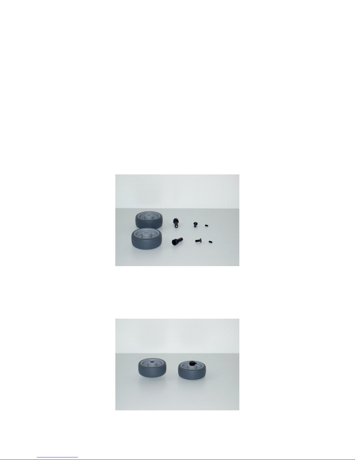
For assembly of the wheels, the components shown in the following picture are required:
First of all, the small setscrew should be screwed into the side of the wheel bush. Next, the
wheel bushes should be pushed as far as possible into the wheels, so that the countersunk
screw M4 can be inserted from the other side. This is then tightened with the appropriate
hexagonal wrench.
The assembled wheels are shown in the next picture:
7
Page 8
CHAPTER 2. BUILDING THE CRASH BOBBY 8
2.2 Step 2 - Assembling the motors
In order that the motors can subsequently be screwed on to the base plate, they must first
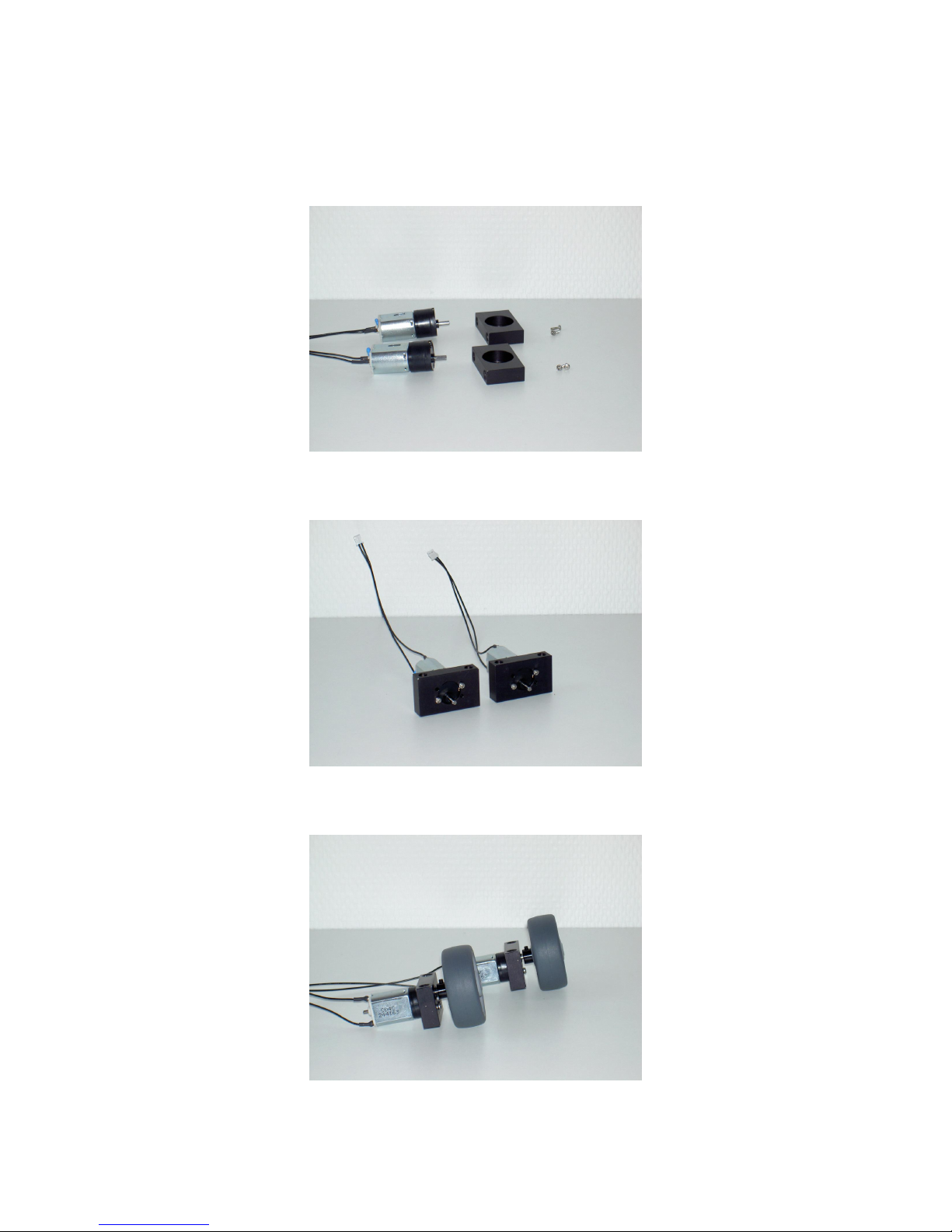
of all be assembled on the motor mounts. The required components are shown in the next
picture:
The motors are located in the large recess of the motor mounts and tightened using the
small screws M2x6. Take care with plastic threads – do not overtighten the screws!
Finally, the pre-assembled wheels are placed on to the motor axles and the setscrew is
tightened:
Page 9
CHAPTER 2. BUILDING THE CRASH BOBBY 9
2.3 Step 3 - Assembling the support wheel
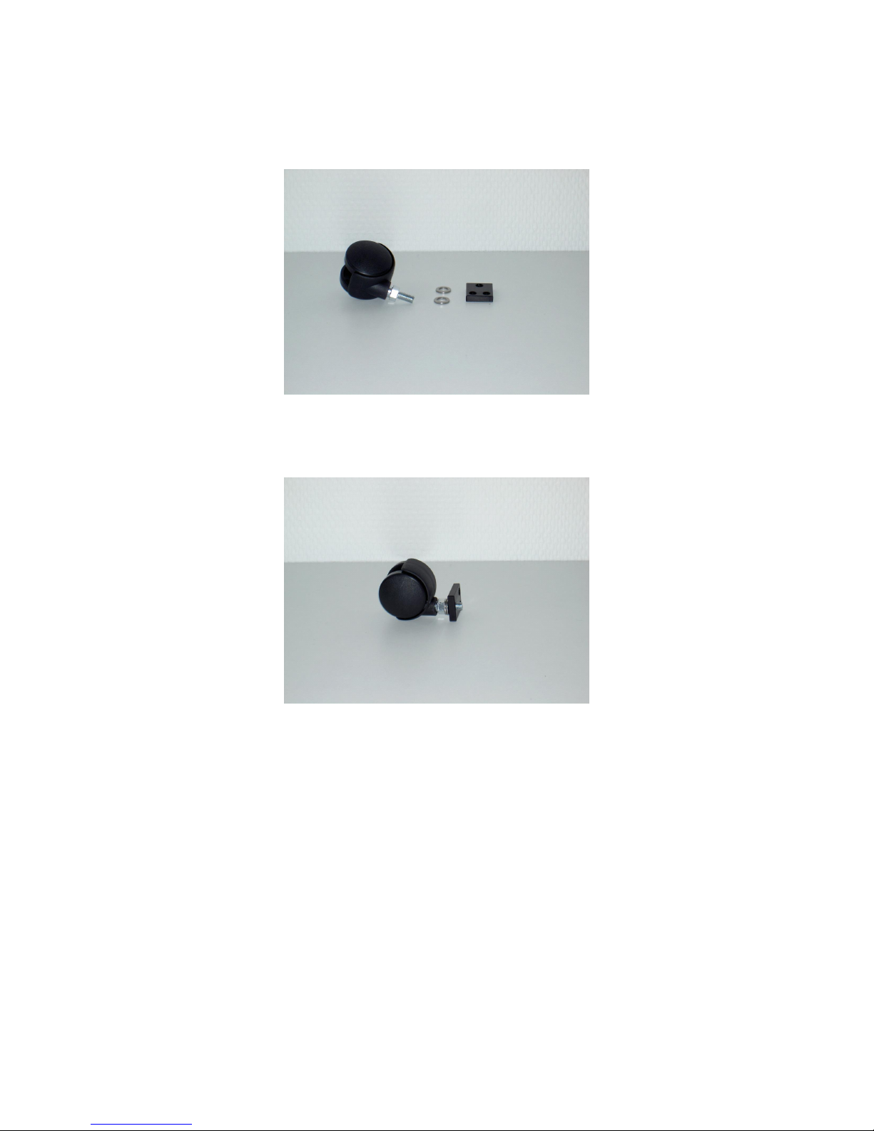
For assembly of the support wheel on the rectangular mounting plate, the components
shown in the following picture are required:
The washers are used as distance spacers and are simply placed on to the threaded pin.
Afterwards, the threaded pin is then screwed firmly into the single threaded hole located
in the rectangular plate.
Page 10
CHAPTER 2. BUILDING THE CRASH BOBBY 10
2.4 Step 4 - Assembling the sensors
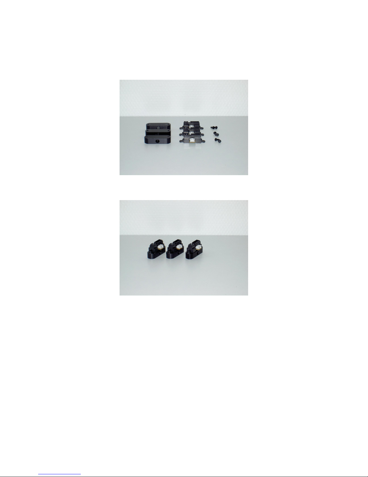
In order that the sensors can subsequently be screwed on to the base plate, they must
first of all be assembled on the sensor mounts. The necessary components are shown in
the following picture:
The three sensors are each screwed to the mounts using two screws. The next picture
shows the assembled sensors:
Page 11

CHAPTER 2. BUILDING THE CRASH BOBBY 11
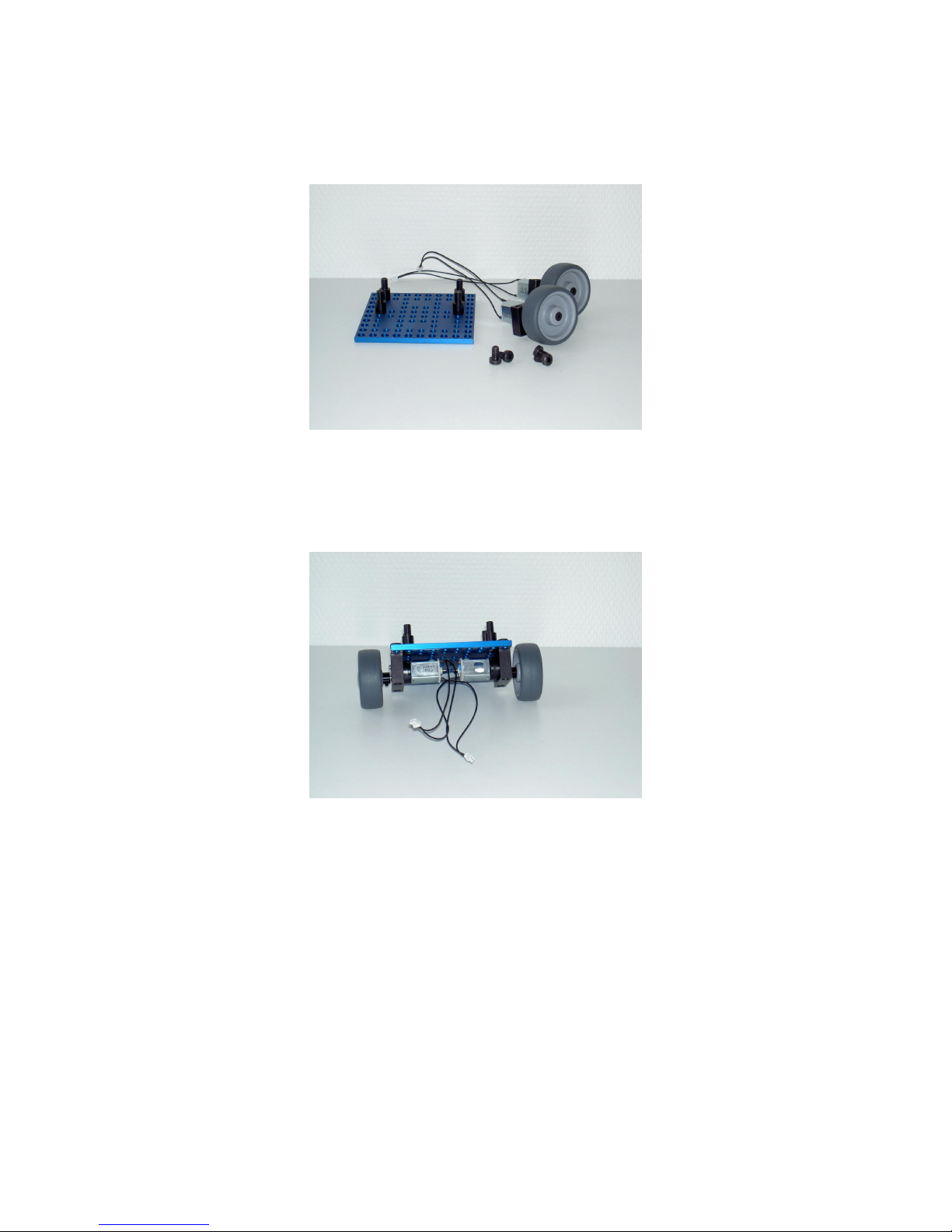
2.5 Step 5 - Fitting the controller board supports
The controller board supports are now screwed into the base plate. The base plate and
four controller board supports are required:
As shown in the following picture, two of the supports are screwed into the corner locations
of the outermost row of threaded holes. The two further supports are then fixed in an offset
position using two threaded holes of the intermediate area.
Page 12
CHAPTER 2. BUILDING THE CRASH BOBBY 12
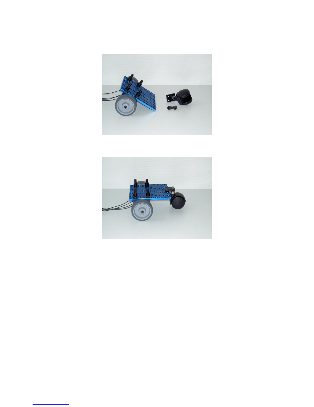
2.6 Step 6 - Mounting the wheels
In this step, the pre-assembled wheels can be mounted on the base plate. The following
components are required:
The wheel supports are located directly next to the controller board suppor ts and screwed
from above with the screws M6x10.
Caution: The wheels must be mounted in such a way that the wheel axles protrude from
the bottom of the support, so that the “ground clearance” is therefore as large as possible.
Page 13
CHAPTER 2. BUILDING THE CRASH BOBBY 13
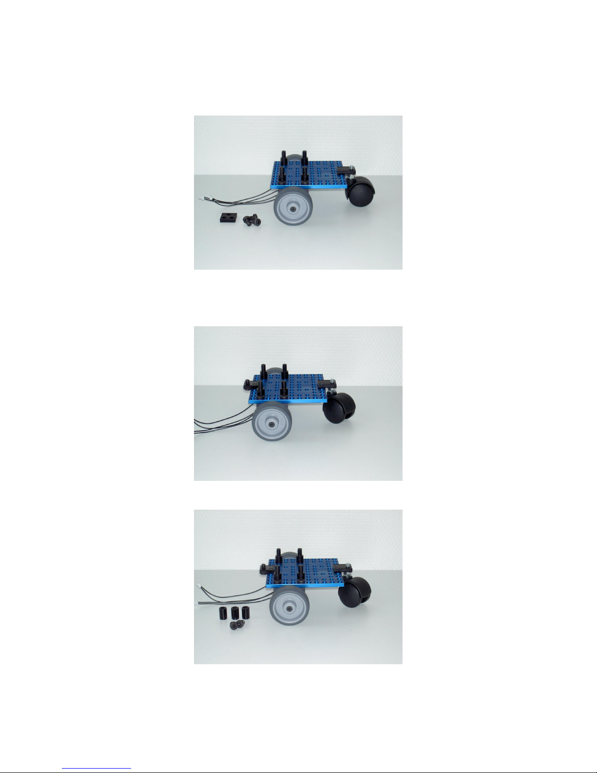
2.7 Step 7 - Mounting the support wheel
Two screws are also required for mounting the pre-assembled suppor t wheel:
The mounting plate is placed on the base plate from above and then screwed on from
below using the screws M6x10.
Page 14
CHAPTER 2. BUILDING THE CRASH BOBBY 14
2.8 Step 8 - Mounting the sensors
Now, the square mounting plate is required, to which the middle distance sensor will subsequently be screwed.
First, one of the three screws M6x10 is screwed firmly into the single threaded hole located
in the plate. Then, in the same way as for the support wheel, the plate is placed on top of
the base plate and screwed on from below:
Next, the three distance pieces and two further screws M6x10 are required:
Page 15

CHAPTER 2. BUILDING THE CRASH BOBBY 15
The distance piece for the middle sensor is fitted on the screw which projects upwards in
the square plate. The two further distance pieces are placed on the front right and left
corner holes of the base plate and screwed on from below:
The longer M6x20 screws are now required in order to screw the pre-assembled sensors
on to the distance pieces:
The sensors are screwed firmly on to the mounts with the connection facing downwards.
The middle sensor should point exactly straight ahead, while the side sensors should point
outwards at a slight angle:
Page 16
CHAPTER 2. BUILDING THE CRASH BOBBY 16
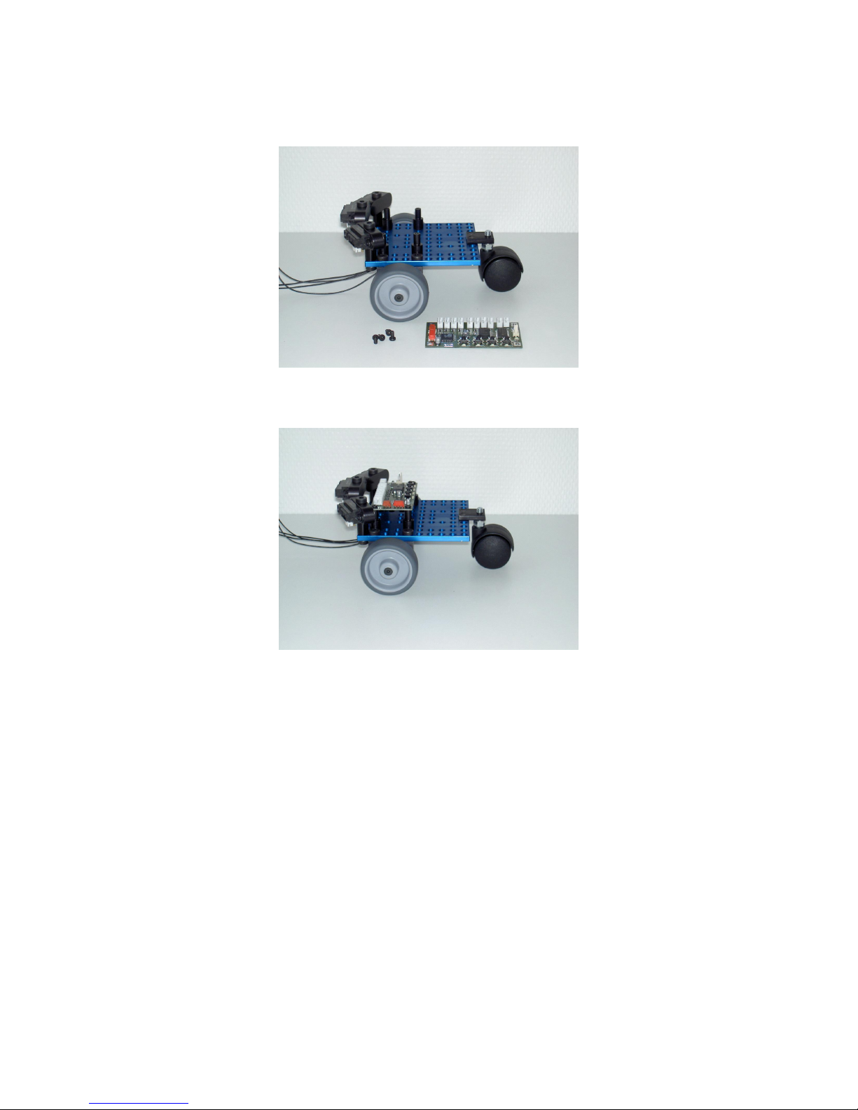
2.9 Step 9 - Attaching the controller board
For the attachment of the controller board, 4 screws M3x6 are required:
With these, the controller board should be screwed on to the four supports so that the
connections for the sensors are located at the front and, therefore, lie close to the sensors.
Page 17
CHAPTER 2. BUILDING THE CRASH BOBBY 17
2.10 Step 10 - Connecting motors and sensors
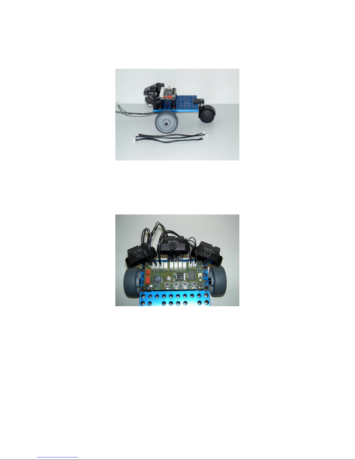
As the last step, it now remains to connect the motors and sensors to the controller board.
For this, the three sensor cables are required:
The sensors are connected to the connections An0 to An3; the motors are connected to
the connections Mot0 and Mot1. In order that the supplied software will run without any
changes being required, the connection configuration should be as follows:
An0=left sensor, An1=middle sensor, An2=right sensor
Mot0=left motor, Mot1=right motor
Finally, the cables should now be “concealed” below the controller board:
Page 18

CHAPTER 2. BUILDING THE CRASH BOBBY 18
Page 19
CHAPTER 2. BUILDING THE CRASH BOBBY 19
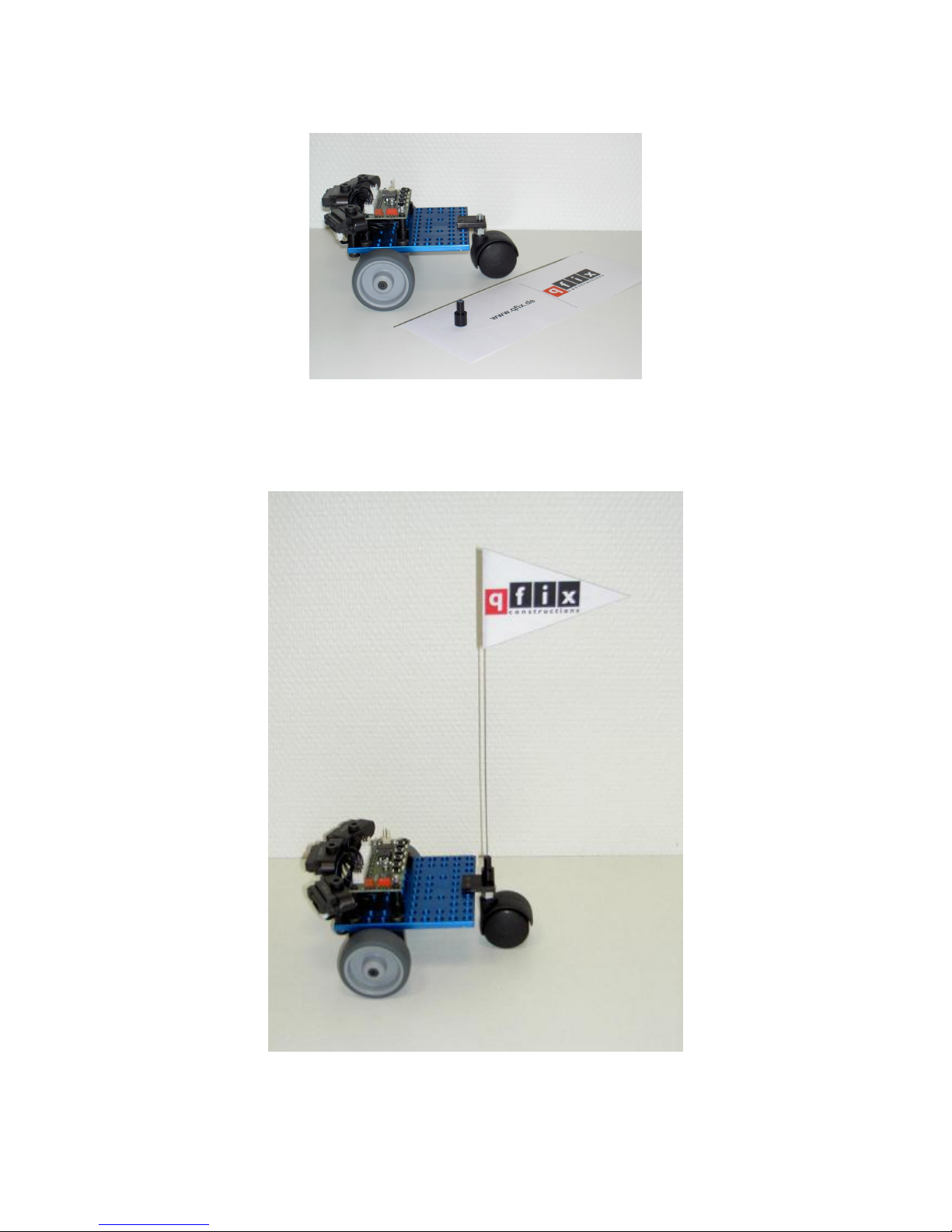
In order to give Crash Bobby the finishing touch, its pennant must of course be attached.
For this, the following parts are required:
The holder for the steel wire is screwed on to the screw of the support wheel, which
projects upwards. Then, the pennant sticker can be detached and the steel wire laid
exactly on the center line, so that the two points of the pennant are brought together in
precise alignment. Now, the finished pennant is pushed into the holder complete!
Page 20
CHAPTER 2. BUILDING THE CRASH BOBBY 20
2.11 Preparing the robot for operation
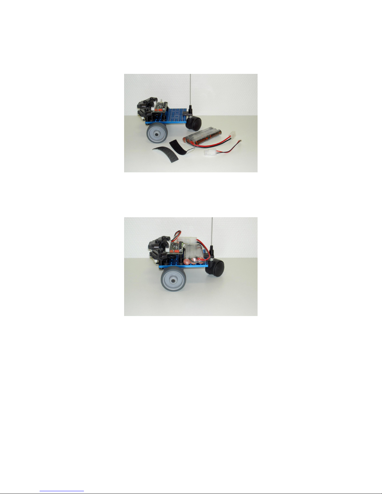
In order to put the robot into operation, a rechargeable battery is required. The following
picture shows the qfix rechargeable battery pack with its components:
The Velcro strip is simply fixed to the base plate with adhesive; the velour strip is positioned
on the underside of the battery pack. One piece of adhesive tape helps to secure the
cable to the battery without being disturbing. After plugging in the adapter cable, the robot
is ready for operation.
Page 21

Chapter 3
Software installation
Note: Instructions and software on this CD are updated regularly. Please check if you
have the most recent version or if there is a new CD version on the website www.qfix.de
(downloads). The version identifier of this CD can be found in the file README.txt in the
main directory of the CD.
3.1 Requirements
The software can be installed under Windows XP or windows 2000 operating systems.
The application has not yet been tested for use with older versions of Windows.
In order to load programs into the qfix controller, it is necessary to use the parallel port
(printer connection).
3.2 Content of the CD
The CD contains the following entries:
• File “README.txt”
• File “LIESMICH.txt”
• File “install.bat”
• Director y “software”
• Director y “doc”
• Director y “WinAVR”
21
Page 22
CHAPTER 3. SOFTWARE INSTALLATION 22
3.3 Installation of the WinAVR software
Concealed behind “WinAVR” is the compiler for the Atmel controller that is used on the
qfix boards.
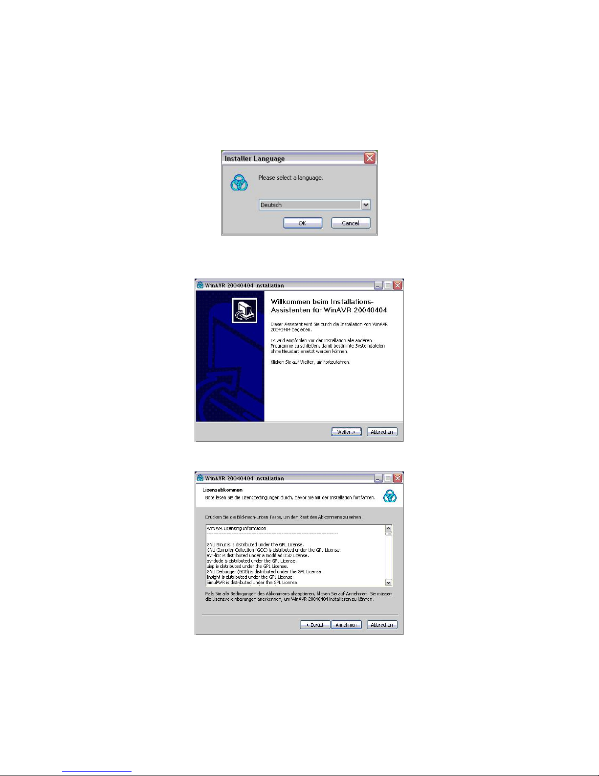
Please start the installation by double clicking on install.bat. First of all, you will be
requested to select the desired language:
Select e.g. English and then click on OK. In the following description, we assume German was chosen. Now, a welcome screen appears:
By clicking on Continue, you reach the license agreement:
Here, please select Accept. Now, a window appears for selection of the target directory:
Page 23

CHAPTER 3. SOFTWARE INSTALLATION 23
Please leave the suggested path unchanged (C:\WinAVR).
Caution: If the wrong path is selected, the supplied programs may not compile correctly!
(However, WinAVR may be uninstalled again at any time and can then be installed correctly.)
Confirm your selection by clicking on Continue. A window opens for the selection of the
components to be installed:
Please leave all entries selected (or select all entries) and then click on Install. Now, a
window opens which shows the installation status by means of a progress bar:
Page 24
CHAPTER 3. SOFTWARE INSTALLATION 24
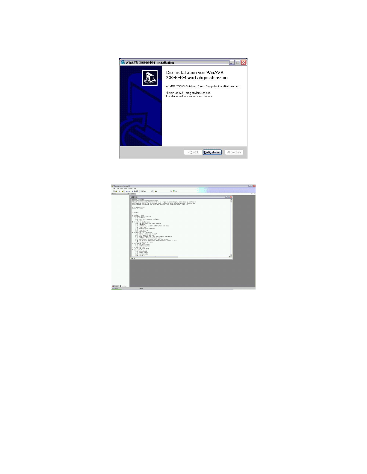
Depending on the computer, this may take a few minutes. When the installation is complete, click on Continue. Finally, the last window opens which you can acknowledge with
Finish:
In some cases, the program “Programmers Notepad” also opens, together with the last
window, in order to display additional information for you to read, concerning WinAVR:
You may simply close this program before or after reading the contents.
Now, the compiler is installed!
3.4 Installation of the qfix sample software
For installation of the qfix sample software it is sufficient to copy the complete directory
named “software” from the CD into any desired directory on the hard disk. You can, for
example, drag the software directly onto your desktop or place it in your “My Documents”
folder.
Page 25

Chapter 4
First steps
This chapter will describe how to put the qfix controller into operation, how to edit and to
compile a program and how to transfer it from the PC into the controller.
4.1 Putting the controller into operation
In order to put the controller into operation, you simply need to connect the battery. The
battery connection socket is protected against polarity reversal. After inserting the plug,
the red Power LED must immediately light up. If it does not light up, please immediately
remove the plug and check the connection.
In order to load a program from the PC into the controller, the download cable must be
plugged into the parallel port (printer connection, LPT1) of the PC and the red plug must
be connected to the larger red socket of the controller board.
4.2 Editing a program
Note: In order to load a demo program into the editor you should have copied the software
directory onto your hard disk as described in section 3.4.
Please start the programming environment “Programmers Notepad” (e.g. in Start → WinAVR
→ Programmers Notepad) and open via the menu File→Open e.g. the qfix demo file
ledTest.cc.
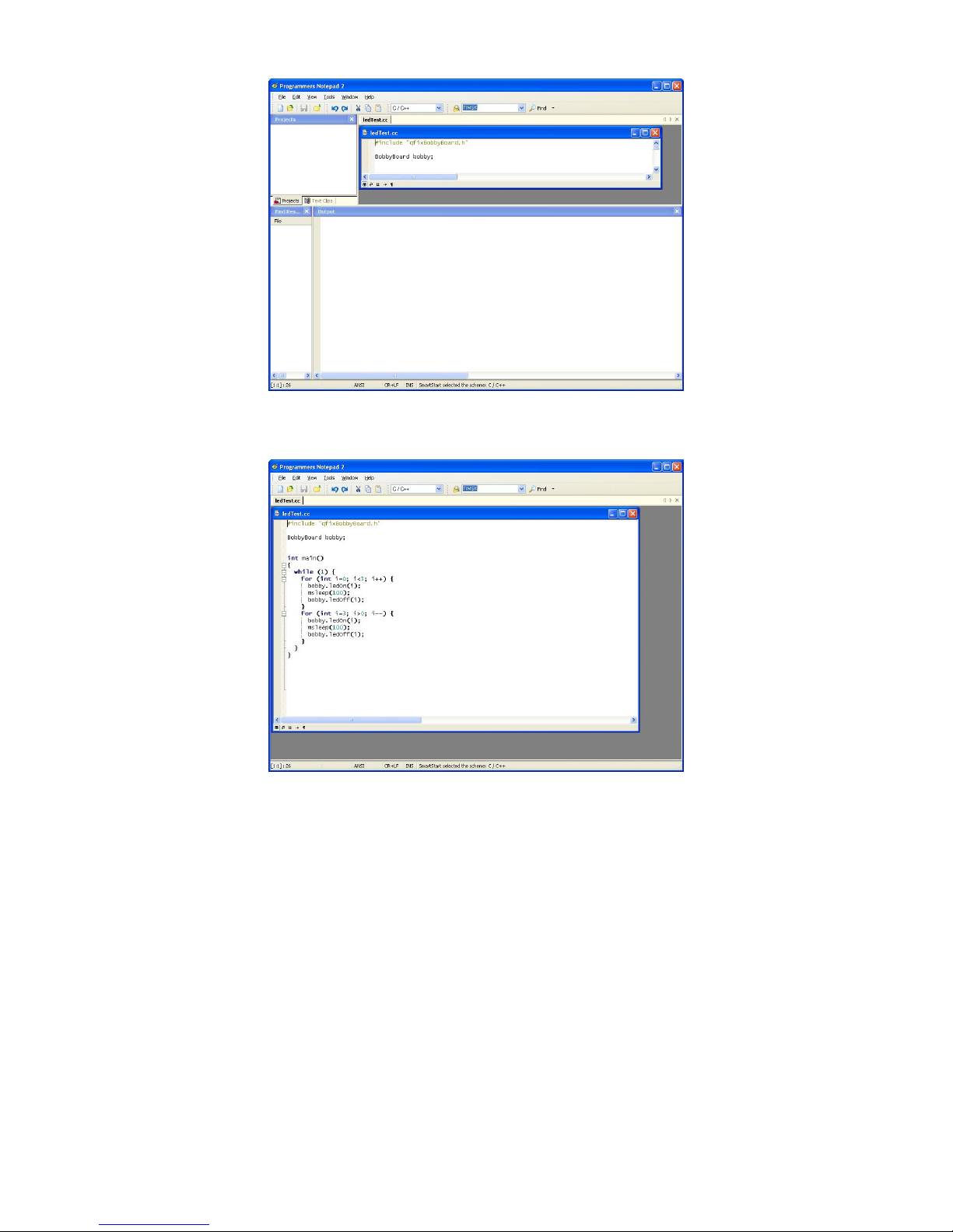
The first time the Programmers Notepad is started, it opens a lot of unnecessary windows:
25
Page 26
CHAPTER 4. FIRST STEPS 26
You can close all windows except the one with the desired source code ledTest.cc. The
editor looks like the following now:
4.3 Compiling a program
In order to compile the program for your board the correct controller must be selected.
The qfix kits currently support the Atmel controllers mega32, mega128 and AT90CAN128.
Crash-Bobby comes with the mega32 controller board, so please select qfix C++ mega32
from the selection list on the toolbar of the editor:
Page 27

CHAPTER 4. FIRST STEPS 27
For compiling the program in the editor simply press F5. A new output window opens at
the bottom of the editor window displaying the status of the compilation:
As you can see in the topmost line of the output window the tool c:→WinAVR→compile-mega32.bat
was called for compilation. If the messages compiling ... and OK occur the compilation
was successful and the program can then be transferred into the controller. If the program
still contains errors these are also displayed here.
Page 28
CHAPTER 4. FIRST STEPS 28
4.4 Downloading the program into the controller
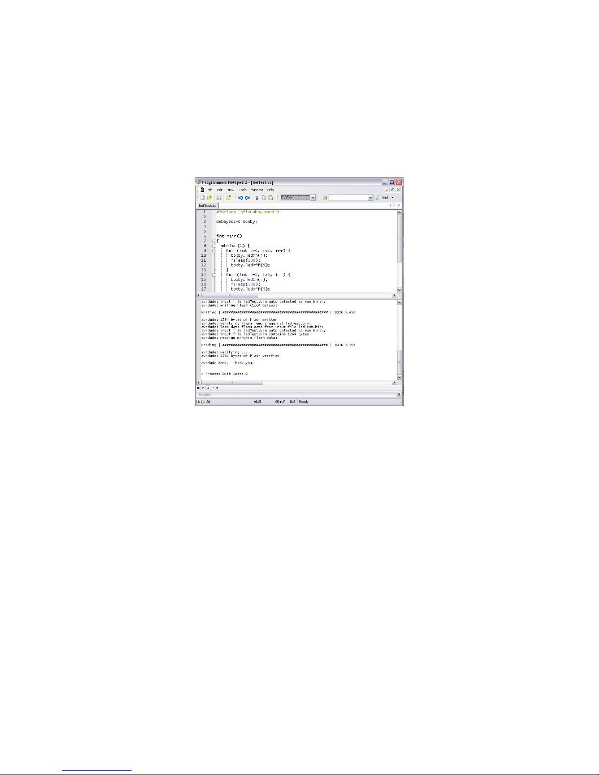
After successful compilation, press F6 to transfer the program to the controller board.
Here, you also have to be sure that the correct controller is selected! The transfer takes
several seconds. Output messages of the used transfer program avrdude are displayed
in the output window.
After a successful download, the controller starts immediately running the program. E.g.
the ledTest sample makes the four LEDs blink.
The same steps (compilation plus download) can be performed for the other sample programs, too. A list of provided samples can be found in the appendix.
If there is a problem transferring the program to the board, please check the status of the
battery. The parallel interface LPT1 should be in mode “ECP” (refer to your BIOS manual).
4.5 Creating your own programs
In order to create a program yourself, the simplest way is to copy an already existing
program file (e.g. “ledTest.cc” to “myFirstTest.cc”) and open this file in the editor.
For programming the controller, the C++ class BobbyBoard can be used. The methods of
this class are described in appendix C.1.
Page 29
Appendix A
Controller circuitry
Clock: 8MHz
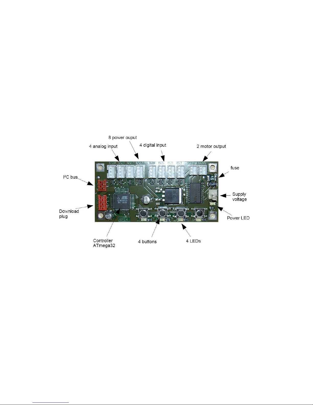
Pin assignment of the three-pole input / output plugs:
• The outer pin is the power output. It can be swithed on and off by the commands
powerOn and powerOff.
• The middle pin is ground.
• The inner pin is the input signal pin. For analog input a voltage of between 0 and 5V
can be impressed. For digital input a voltage of 0 or 5V can be impressed.
29
Page 30

Appendix B
Standard Programm
#include "qfixBobbyBoard.h"
BobbyBoard bobby;
int main()
{
/* Here go the commands */
}
The standard program can be used as a starting point for own programs.
First, it includes the required library qfixBobbyBoard.h and then creates an object bobby.
This object can be used to invoke arbitrary commands.
For example, the command bobby.<command>; calls the “method” command of the
object bobby.
All methods of class BobbyBoard are described in appendix C.
30
Page 31

Appendix C
Command Overview
Each of the following tables describes one class with their methods. To call these methods,
an object of this class must exist. Please refer to the sample programs on the CD.
The column RValue in the class table describes the type of the return value for each
method. The following types are used:
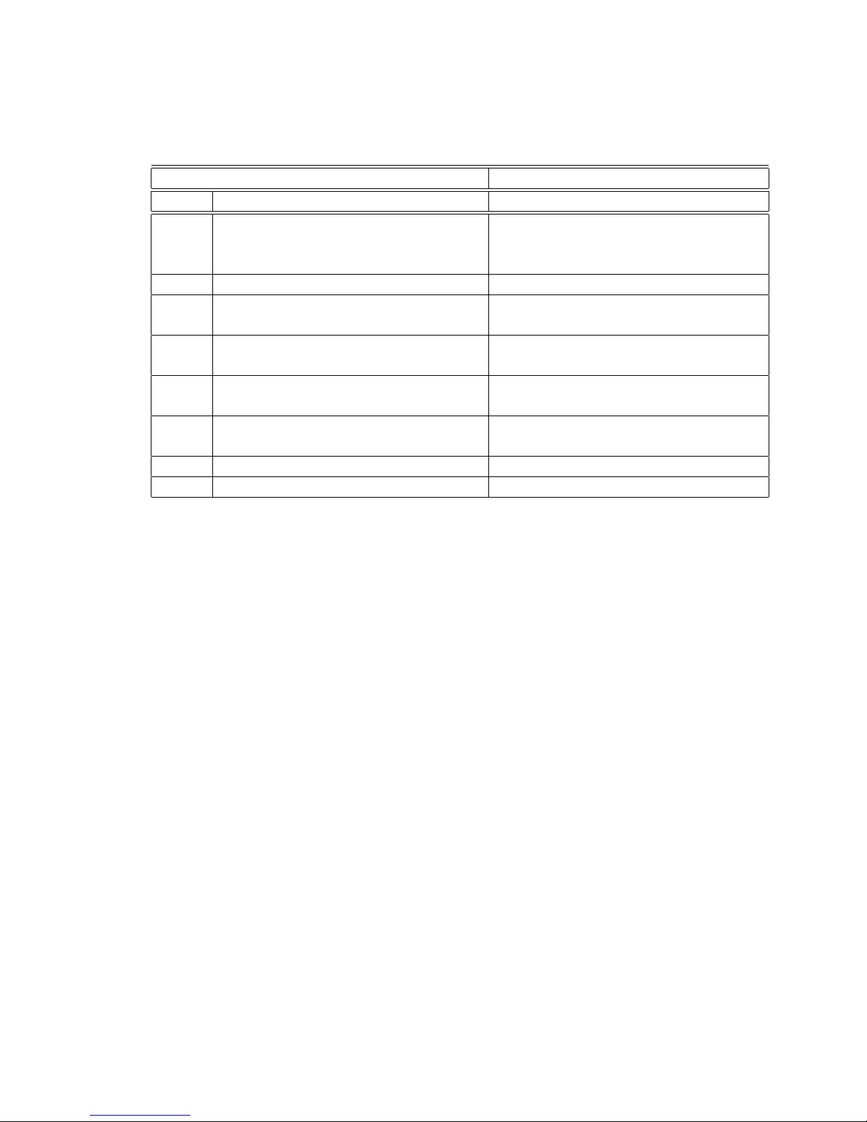
Type Description
void No value (used as return type in functions with-
out return value)
bool Boolean value (true or false)
int
Integer value (-32767 – 32768)
char Character (e.g. ’A’)
char* Pointer to a character. This is used for char-
acter strings as parameters to a function (e.g.
"Hello")
31
Page 32

APPENDIX C. COMMAND OVERVIEW 32
C.1 Class BobbyBoard
Class: BobbyBoard File: qfixBobbyBoard.h
RValue Method Description
BobbyBoard() This constructor is called automatically
when the object is created. It initializes the
object as follows: The motors are set to 0,
all LEDs are off, all power outputs are on.
void ledOn(int i) Puts on LED with index i. i must be in
the range 0 to 3.
void ledOff(int i) Puts off LED with index i. i must be in
the range 0 to 3.
void ledsOff() Puts off all LEDs.
void led(int i, bool state) Puts on LED with index i if state=true,
else off. i must be in the range 0 to 3.
bool button(int i) Returns true if the button with index i is
pressed, else false. i must be in the
range 0 to 3.
bool waitForButton(int i) Waits until the button with index i is
pressed and released again. i must be
in the range 0 to 3.
void motor(int i, int speed) Sets the motor with index i to the value
speed which must be in the range -255 to
+255. A value of 0 puts off the motor..
void
motors(int motor0, int motor1) Sets both motors to the respective values
motor0 and motor1. Both values must be
in the range -255 to +255.
void motorsOff() Puts off both motors.
int analog(int i) Returns the value of the analog input with
index i. The returned value is in the range
0-255. i must be in the range 0 to 3.
bool digital(int i) Returns true if the digital input with index
i is high (+5V), else false. i must be in
the range 0 to 3.
void powerOn(int i) Puts on the power output with index i. i
must be in the range 0 to 7.
void powerOff(int i) Puts off the power output with index i. i
must be in the range 0 to 7.
void power(int i, bool state) Puts on the power output with index i if
state=true. i must be in the range 0 to
7.
void ledMeter(int i) Displays the given value in the range 0-
255 using the four LEDs.
void sleep(int s) Waits for s seconds.
void msleep(int ms) Waits for ms milliseconds.
Page 33
APPENDIX C. COMMAND OVERVIEW 33
C.2 Class LCD
The class LCD supports the qfix LC-displays. The used display must be connecte via the
I2C-bus to the controller board.
Class: LCD File: qfixLCD.h
RValue Method Description
LCD() The constructor initializes the connection
to the display, clears the display and puts
the cursor to (0,0).
void clear() Clears the display.
void print(int i) Prints the number i at the current cursor
position.
void print(char* s) Prints the string s at the current cursor po-
sition.
void print(int row, int col, int i) Prints the number i at row row and col-
umn col.
void print(int row, int col, char* s) Prints the string s at row row and column
col.
void
lightOn() Puts on the backlight.
void lightOff() Puts off the backlight.
Page 34

Appendix D
Demo programs
This chapter describes tre sample programs delivered with the CD.
analogTest
This program outputs a value at the analog port 0 via the LEDs. At a voltage of 0V (internal
value 0) no LEDs light up; at a voltage of 5V (internal value 255) all four LEDs light up. In
between, the corresponding number of LEDs light up.
bobbyTest
This program allows the Crash Bobby to drive around and to avoid obstacles. For this, the
three distance sensors must be connected to the controller as follows:
• Left sensor: An0
• Middle sensor: An1
• Right sensor: An2
Die Motoren m¨ussen folgendermaßen angeschlossen sein:
• Left motor: Mo0
• Right motor: Mo1
Operation:
At the start, the LED 0 lights up. Now, the sensors must be calibrated to the “critical
distance”. For this, you must hold your hand approx. 10-20 cm in front of the middle
sensor and press button 0. Now, the robot can be placed down.
After pressing button 2, it will drive off.
Pressing button 0 will stop it again; by pressing button 2, it will start up once more. To
carry out a recalibration, the battery cable must be briefly unplugged.
34
Page 35

APPENDIX D. DEMO PROGRAMS 35
buttonTest
With this program, pressing one of the buttons will cause the corresponding LED to light
up.
digitalTest
This program tests all four digital inputs and when a voltage is applied it will cause the
corresponding LED to light up.
lcdTest
This program demonstrates the usage of the qfix LC-display.
lcdChangeID
With this program it is possible to change the logical ID of a LC-display. This is needed
whenever multiple display are connected to the controller board.
ledTest
This program causes the four LEDs to flash in similar fashion to the Knight Rider automobile.
lineFollow
This program uses the qfix line sensor to move along a line.
For this, the line sensor must be connected to analog input 3.
After program start, place the robot next to the line and press button 0. Then, place the
robot exactly on the line and press button 1. Now, button 2 starts the robot.
While moving, the robot can be stopped by pressing button 0. Button 1 starts again.
motorTest
This program controls both motors at 4 different speeds in both directions. The 4 possible
choices can be selected via the buttons.
Page 36

APPENDIX D. DEMO PROGRAMS 36
myTest
This program has no actual function and merely contains an empty base structure for your
own programs. To use it for this purpose, the whole directory should be copied.
powerOutTest
This program corresponds to the program “ledTest”, but with the difference that instead of
switching the LEDs, the power outputs are switched.
slaveBoardTest
This program shows how to connect two BobbyBoards via the I2C-bus. One board is the
master, the other one the slave. Thus, she sample consists of two programs: master.cc
and slaveBoard.cc.
The slave program is compiled and transferred to the slave board. It simply waits for any
command (like “motor on”) by the master and reacts according to the command. The
program code must not be known or understood (“black box pr inciple”).
In the master program two objects are instantiated: (bobby and slave). It always polls the
buttons of the master board and sends a command to the slave according to the pressed
button:
• Master button 0 switches slave LED 0 on and off.
• Master button 1 switches slave motor 0 on and off.
• Master button 2 checks slave button 0 and returns its value on master LED 2.
• Master button 3 checks slave digital in 0 and returns its value on master LED 3.
vehicle
This program corresponds to the Braitenberg vehicle. It drives around and avoids obstacles. This is similar to the program “bobbyTest”, but is constructed in a much simpler
manner and uses only 2 sensors.
For this, the three distance sensors must be connected to the controller as follows:
• Left sensor: An0
• Right sensor: An1
The motors must be connected as follows:
Page 37
APPENDIX D. DEMO PROGRAMS 37
• Left motor: Mo0
• Right motor: Mo1
KTB mechatronics GmbH Tel.: +49-7344-929330
Helfensteinerstrasse 26 Fax.: +49-7344-929331
89143 Blaubeuren Mail: info@qfix.de
GERMANY
powered by
 Loading...