

QED MusiQ RFS, MusiQ IS Instruction Manual
MusiQ
MusiQ User Instructions
Declaration of Conformity, Safety
DECLARATION OF CONFORMITY
All MusiQ models have been designed and independently tested to be in compliance with the following standards:
Safety - EN60065:1993/IEC65, EMC-EN55013:1990, EN50082-1:1997, EN61000-3-2:1995, EN61000-3-3:1995
SAFETY
This symbol is to alert the user to the presence of
dangerous voltages inside the MusiQ enclosure.
To reduce the risk of electric shock do not remove
any parts of the MusiQ.
Read all the instructions before connecting or operating the MusiQ. Pay particular attention to the safety information.
Keep this manual so you can refer to these safety instructions.
WARNING:
There are no user serviceable parts inside. Refer all servicing to qualified service personnel.
WARNING:
To reduce the risk of fire or electric shock, do not expose the MusiQ to moisture or water. Do not allow foreign
objects to get into the enclosure. If the unit is exposed to moisture, or a foreign object gets into the enclosure,
immediately disconnect the power cord from the wall. Take the unit to a qualified service person for inspection
and necessary repairs.
The RFS MusiQ product must only be used with the supplied aerial. The aerial must not be attached via an extension
cable. Under no circumstances should the MusiQ be connected to any other receiving system.
Installation of the KMM Keypad/Display and the RF Docking Handset should only be carried out by a competent
person with reasonable DIY knowledge or a professional builder/Installer.
Clean the MusiQ only with a dry cloth or a vacuum cleaner.
Place the MusiQ on a fixed, level surface strong enough to support its weight. Keep the MusiQ away from radiators,
heat registers, stoves, or any other appliance that produces heat.
If the MusiQ is placed in an enclosure, there must be sufficient ventilation of the enclosure to allow proper cooling.
Connect the MusiQ to the power outlet only with the supplied 3-pin grounded power supply cable or an exact
equivalent. The cable should be connected to a properly grounded 3-pin wall outlet. Do not modify the supplied cable
in any way. Do not use extension cords.
Do not route the power cord where it will be crushed, pinched, bent at severe angles, exposed to heat, or damaged in
any way. If the cable shows any sign of wear or damage, immediately stop using it and obtain a proper replacement
from a qualified service agency or from the QED service department.
If the MusiQ shows signs of improper operation, or if it has been dropped or damaged in any way, immediately
disconnect the power cord from the wall. Take the MusiQ to a qualified service person for inspection and
necessary repairs.
The MusiQ product should not be used in locations where it will be subjected to high levels of radiated R.F., or where
its connecting cables will be subjected to high levels of R.F. interference from other sources.
GUARANTEE
All products are covered by a 2 year guarantee for parts and labour. Site visits are not covered by this guarantee and
will normally result in a call out charge if such a visit is requested or deemed necessary.
This symbol is to alert the user to important
operating instructions in the owner's information
accompanying the MusiQ.
CONTENTS
Page
Section 1: INTRODUCTION AND DESCRIPTION 02
Section 2: INSTALLATION 04
Section 3:
CONFIGURING THE SYSTEM 12
Section 4:
TROUBLESHOOTING 15
Section 5:
TECHNICAL SPECIFICATION 16
Section 6:
OPERATION 16
Section 7:
ADDITIONAL NOTES 20
01
Contents
02
MusiQ User Instructions
Introduction and Description
1 INTRODUCTION
This manual is designed to enable you to install your MusiQ system, to configure it to meet your particular needs and
to use the system as required.
1.1 OVERVIEW
MusiQ enables you to expand your Hi-Fi system into other areas of your home or commercial premises, and to control
two of its sources remotely. Inside each MusiQ are two Stereo Pre-amplifiers and Power amplifiers that distribute sound
from your main Hi-Fi sources, such as CD and tuner, to additional sets of loudspeakers.
A typical domestic MusiQ application would be to add suitable pairs of speakers in the kitchen and master bedroom.
This would, for example, allow one person to listen to the radio in the kitchen while another listens to the CD player
in the bedroom.
MusiQ allows you to select and control* the same or different sources at any time in each remote zone, and to have
independent control over the volume level in each location.
MusiQ features high quality audio circuitry that is capable of giving excellent results with many types of loudspeakers.
* See System Features- Built-in Source Control
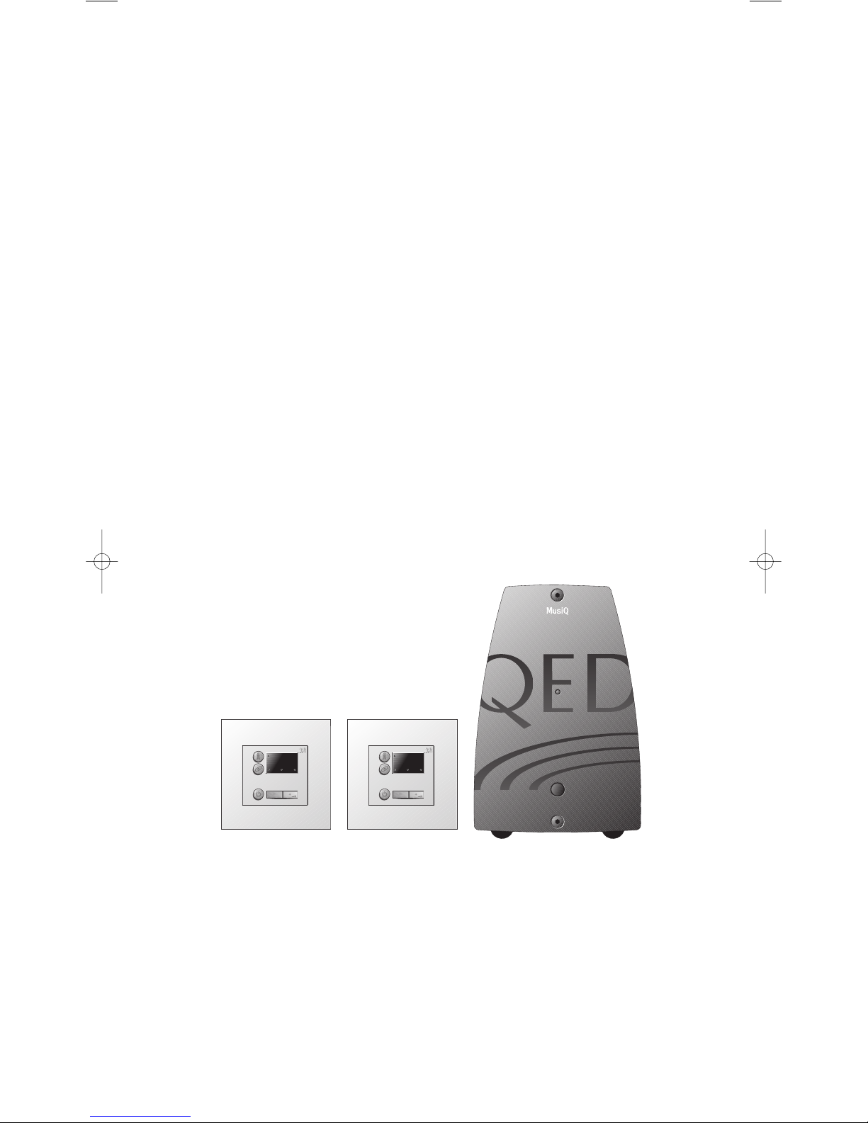
1.2 MUSIQ VARIANTS
MusiQ is available in two model types: IS and RFS. Both models have the same basic functionality; the difference being
in how each model is controlled and the way in which its status is displayed.
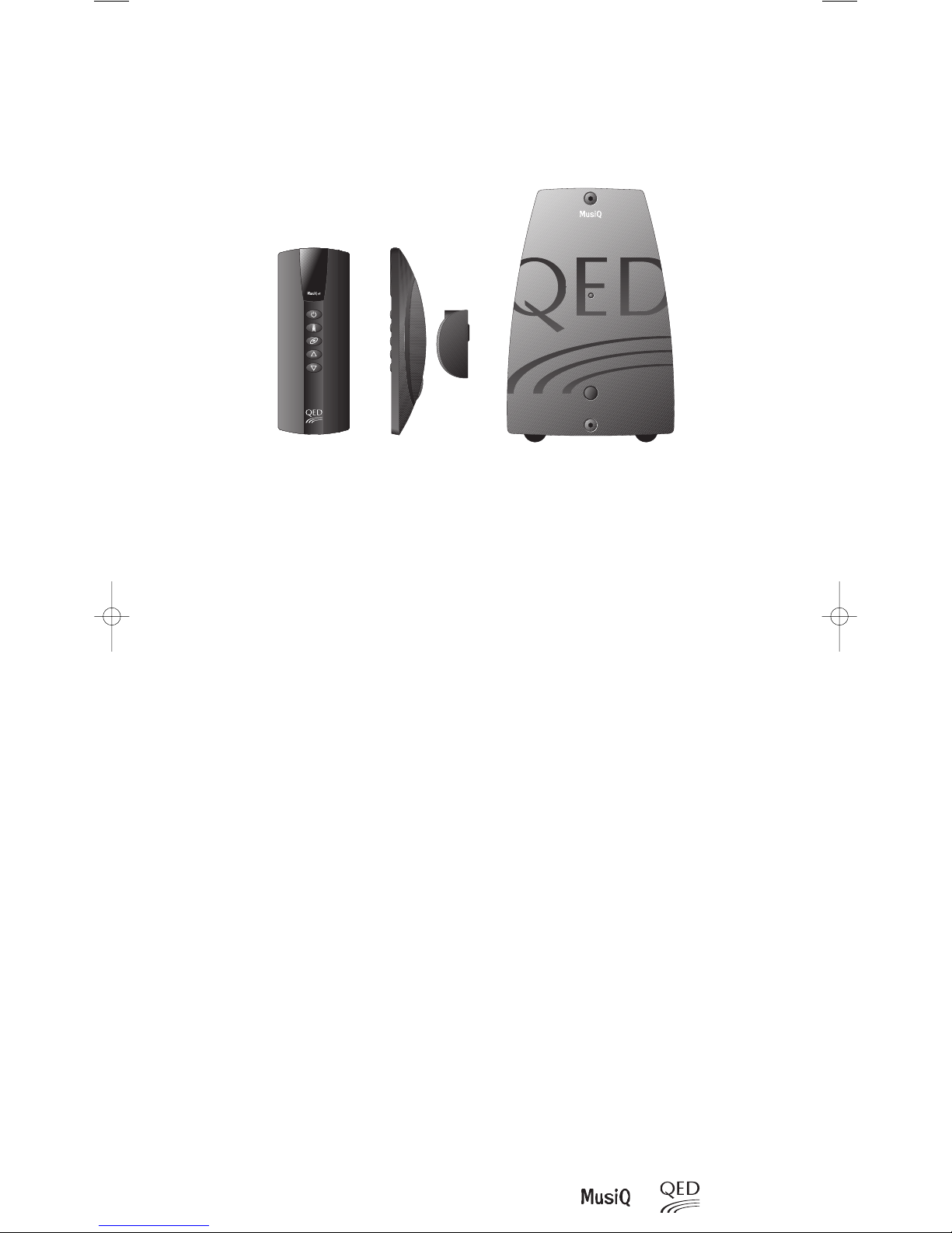
MusiQ IS - Control is via a wall mounted keypad (KMM Keypad/Sensor) in each remote room/zone. The keypad
controls the MusiQ and, when applicable, the sensor function acts as a universal infra-red link to relay control
commands to a source component from that unit's infra-red handset.
The MusiQ IS System includes Controller
and two KMM Keypads
MusiQ IS System
03
Introduction and Description
The MusiQ RFS System includes Controller
and two Docking RF Handsets.
MusiQ RFS System
MusiQ RFS - This model includes the front panel control option and in addition offers full remote control via a wireless
RF (radio frequency) handset. Additionally, if the handset is mounted on a hard-wired docking station, the handset can
be used as a universal infra-red link in the same way as the Keypad/Sensor to relay control commands to a source
component from that unit's infra-red handset.
The RFS version is particularly suited as a retro-fit in domestic installations where speaker wires are already in place or
can be easily routed. It can also be used for commercial applications requiring more flexible control.
04
MusiQ User Instructions
Introduction and Description, Installation
1.3 SYSTEM FEATURES
Note: The following features are common to all MusiQ variants.
• Two Stereo Source inputs - These inputs will normally be from a Tuner and CD player. They can, however, be
connected to any source which provides a line level output between 500 mV and 2.0 V rms.
• Microphone input via a 3.5mm jack socket. Announcements can be made over one or both Zones. For the best
performance, an Electret Condenser type microphone is recommended with an impedance of approximately 600
ohms. Microphones featuring an on/off switch terminated in a 2.5 mm jack are particularly suitable as they will
operate the microphone paging trigger.
• Two remote keypad inputs - The keypad socket enables remote control of each MusiQ zone via a wired link to a
MusiQ KMM Keypad module. Also used if the RF Handset docking station is to be used for IR relay.
• Four infra-red (window emitter) outputs via 3.5 mm jack sockets. These outputs enable up to four sources to be
controlled through MusiQ by re-transmitting IR control codes from remote zones (and from the unit’s internal
software), directly into the IR sensors of the source components.
• SDB (Serial Data Bus connection) - This allows multiple MusiQ units to be connected together, enabling larger
installations to be constructed and controlled from a single point.
• Active EQ Sound Enhancement - Each Zone can be configured independently to enhance the sound image. This is
particularly useful when using MusiQ with smaller loudspeakers that do not have a full frequency range.
• Party Mode - When you are having a party, MusiQ lets you control all zones from a single keypad. This feature is
extremely useful in multiple MusiQ installations where you want to listen to the same source in all zones at a
common volume level.
• Built in source control - Prime CD & Tuner control functions have been embedded into MusiQ for some of the most
popular brands of Hi-Fi equipment (See Specification section for list of supported brands). This means that with a
simple button press on the wall mounted keypad, control panel keypad or RF handset you can skip presets on the
Tuner, start the CD player and even skip tracks and discs. No need to carry a second remote around the house!
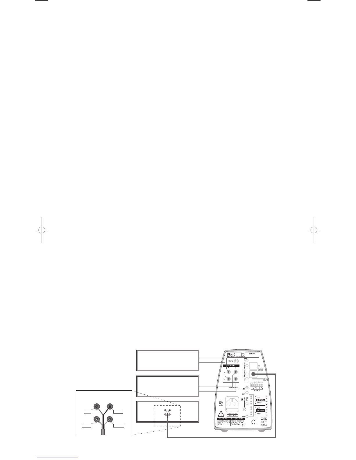
2 INSTALLATION
2.1 Source Connection Options
There are essentially two different types of connection
2.2 Direct Connection of Hi-Fi Separates
This involves connecting the MusiQ directly to two pieces of source equipment such as a CD player and a Tuner (see
diagram below). A loop through cable is provided to allow the sources to be shared with a normal Hi-Fi amplifier.
The Tuner should be connected to Input 1 and the CD should be connected to input 2. Connecting the sources up in
this manner enables the loop through cable to be used as shown in the following diagram. Use standard shielded
phono to phono cables to connect the sources to the appropriate inputs on the MusiQ. Ensure that care is taken to
maintain channel continuity between the left and the right channels.
2.3 Connection of Mini & Micro Hi-Fi Systems
TUNER
CD
AMPLIFIER
Yellow
Black
White
Red
R
L
TUNER
CD
05
Installation
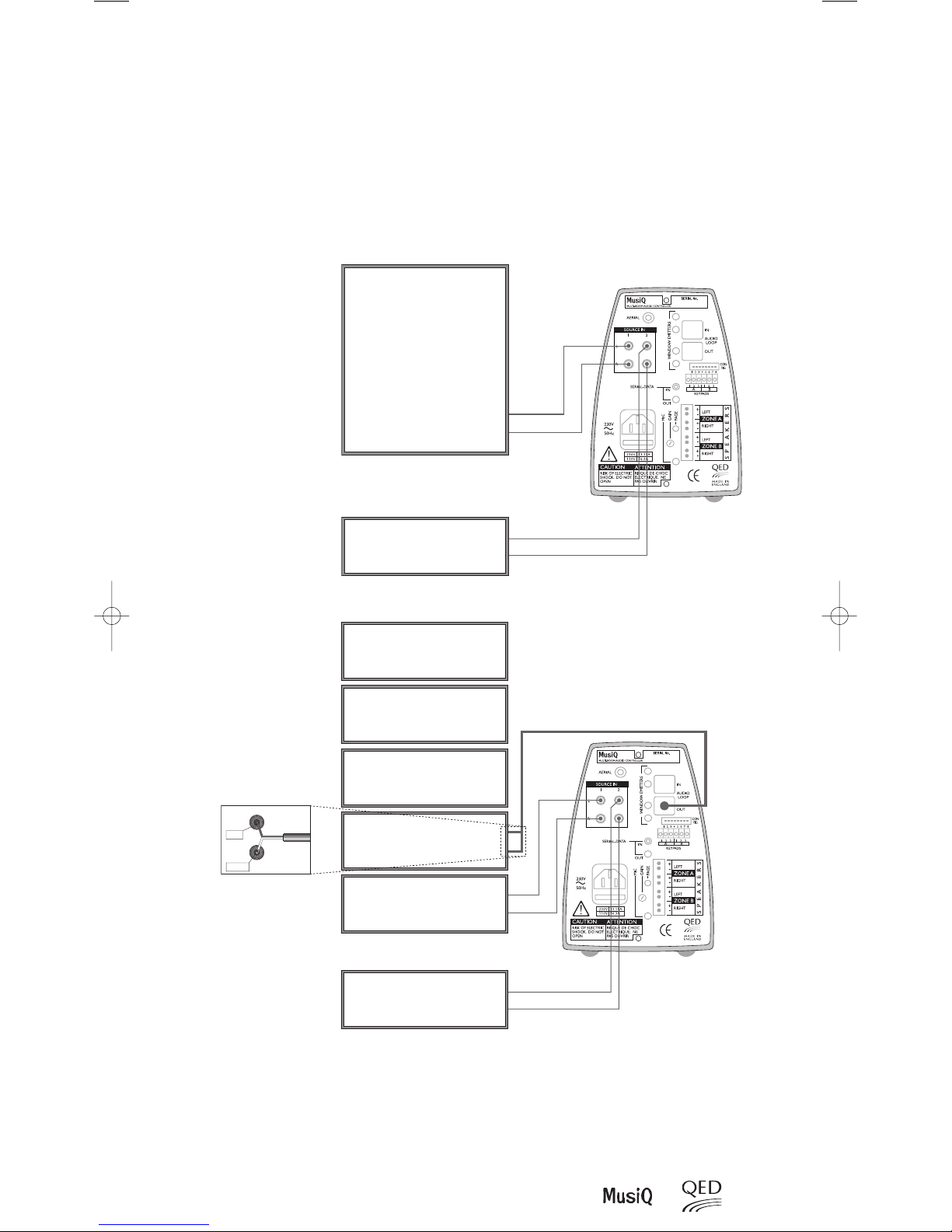
When using an integrated Hi-Fi system without individual source outputs, the recommended connection is to the
“Line Out” sockets. These sockets are provided on many systems and may be labelled as “Aux Out” or “Tape out”.
Most Mini & Micro systems route the currently selected source to these sockets, this enables MusiQ to distribute the
sound from the main system into other areas with independent volume control. Many of these systems can be
controlled remotely through MusiQ using their own handset. However, it should be noted that most Mini & Micro
systems ‘enable’ only the last source to receive a command. This may be inconvenient if two listeners want to listen
to different sources!
Connection to a Mini or Micro
System
Connection to Hi-Fi Separates using
the Amplifier’s Tape Output
When connecting more than two source components it may be more convenient to use the Tape Output sockets
from the main amplifier. This type of connection enables access to all source components by using the ‘Record
Out’ signal. Whatever source is selected on the main amplifier will be routed through to the MusiQ for distribution.
Some amplifiers have a separate record selector which enables the MusiQ to receive a different source to that
being played by the main amplifier.
MINI SYSTEM
(Integrated CD, Tuner etc)
Tape Out, Aux. Out or Line Out
AUX. SOURCE
e.g. VCR, Multi-disc CD, 2nd Tuner etc.
DVD
TUNER
CD
TAP E
Tape In
AMPLIFIER
Tape Out
AUX. SOURCE
e.g. VCR, Multi-disc CD,
2nd Tuner etc
Out
Red
White
R
L
TAPE
06
MusiQ User Instructions
2.5 GENERAL INFORMATION
2.5.1 COMPONENT LOCATION
Locate MusiQ near to the components that you wish to connect. Ensure that adequate ventilation is allowed around
the MusiQ case as this can become warm under use. When installing the MusiQ RFS ensure that both the unit and
docking handset (if located on a wall) are positioned away from large metal objects such as filing cabinets. These can
block the radio signal and reduce the effective control range of the RF Handset. In most installations RF reception
should not be a problem, however you are advised to note the following warning:-
WARNING: IMPORTANT INFORMATION: Always check the operation of the RF handset before installing wires. Do
this by temporarily connecting a music source and speakers to MusiQ, and then checking that you are able to operate
the unit from all locations where you want control. If you are installing an RFS check that the RF receive symbol stays
on continuously when a button is pressed on the RF Handset. Any flickering indicates poor reception. This test is
particularly important before affixing the RF docking port.
2.5.2 EMBEDDED SOURCE CONTROL COMMANDS
To enable easy control of Tuner and CD source components the MusiQ has a number of prime control functions built
into its software. This means, for example, that its possible to skip tuner stations or tracks on a CD without having to
use a separate handset. The available control functions are detailed in Section 6.4.
For this feature to work correctly you need to ensure that the source components are compatible with the latest version
of the MusiQ software. The supported brands/operating codes are as follows:
• RC-5 - A Philips code set used by many other companies including Arcam, Linn and Marantz.
Caution: Some manufacturers who claim to use this code set do not follow the correct protocol and therefore their equipment may not respond
correctly, or at all.
• Denon Caution: MusiQ will operate tuners with direct preset selection only.
• Pioneer
• Sony
• Yamaha
Please Note: Every effort has been made to ensure compatibility with the latest models of the above branded
equipment. However, compatibility cannot be guaranteed. We strongly recommend that you confirm operation with
the equipment you plan to use. If in doubt, consult with the Hi-Fi Dealer supplying the MusiQ product.
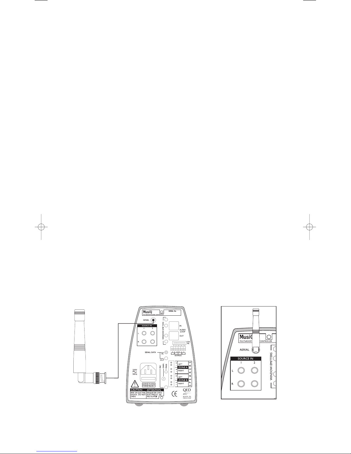
2.5.3 AERIAL CONNECTION (RFS Model only)
The Wireless Control System employed by the RFS Controller requires a special aerial to be fitted as shown.
Installation
RF/RFS AERIAL
Rotate bezel to lock into place
07
Installation
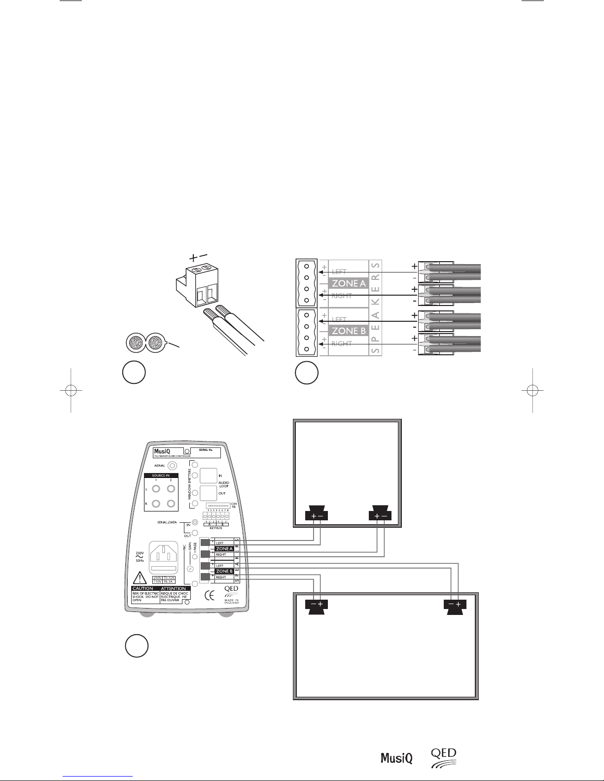
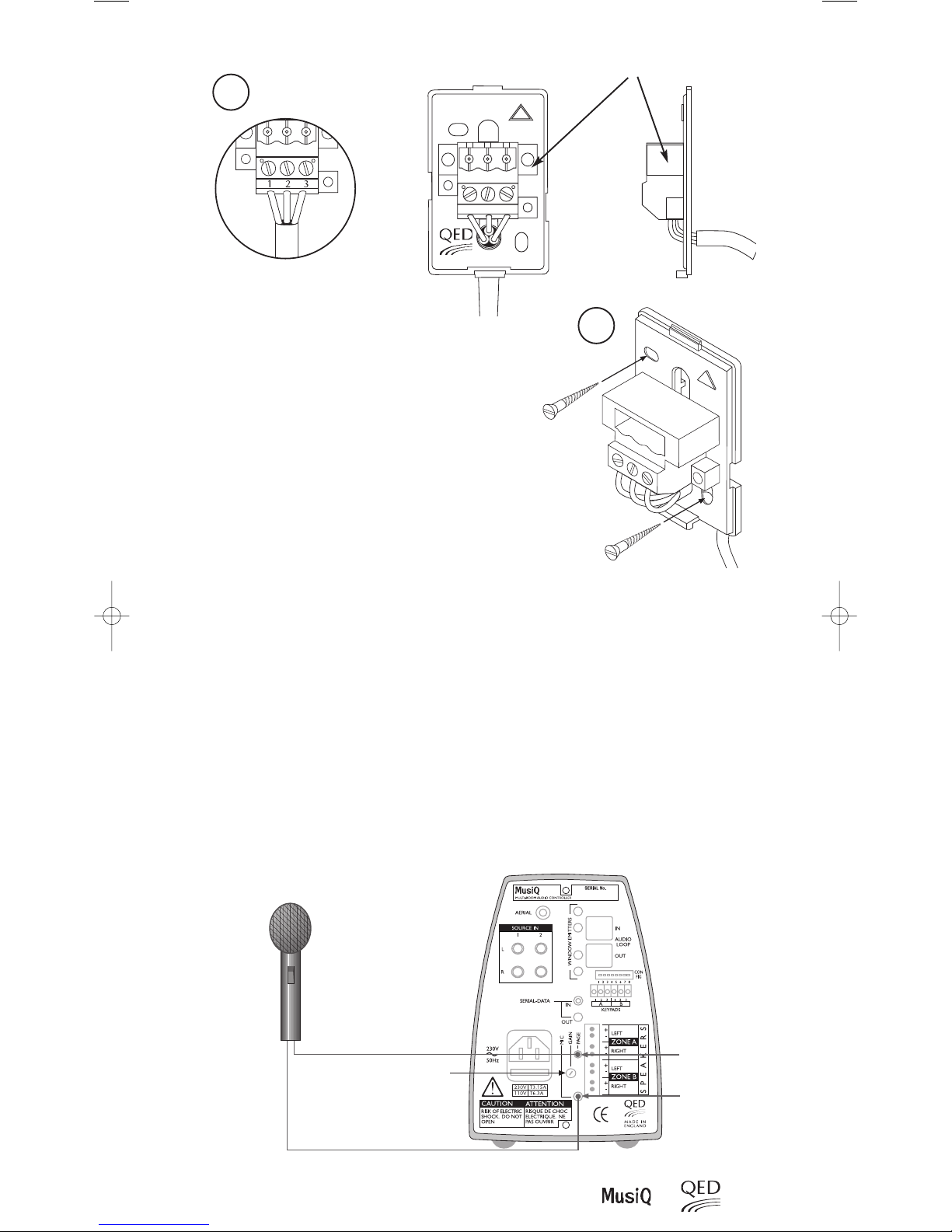
2.5.4 SPEAKER CONNECTIONS
Note: The recommended speaker impedance for use with MusiQ is 8 ohms.
The minimum impedance for use with MusiQ is 4 ohms.
Use the supplied quick-fit terminals for all speaker cable connections.
Strip back each conductor's outer insulation by 6mm, insert bare wire into quick fit plug and secure using the screw
terminal fixing. Take care to ensure proper polarity (note "+" is normally identified by a fine rib running along one edge).
BE CAREFUL AND BE PATIENT. It is essential to have the speakers correctly connected for maximum system enjoyment.
“Out of phase” loudspeaker hookups (where one speaker in a stereo pair is inadvertently connected “+” to “-” and vice
versa) may not be immediately noticeable but will not be as pleasing in the long term as a properly connected stereo pair.
Route speaker cables from each remote Zone to the rear of the MusiQ and connect as follows:
1
2
3
USING QUICK FIT PLUGS SUPPLIED
CONNECT UP SPEAKERS AS SHOWN
Speaker Cable
Positive
ROOM ONE
LEFT RIGHT
RIGHT LEFT
ROOM TWO
08
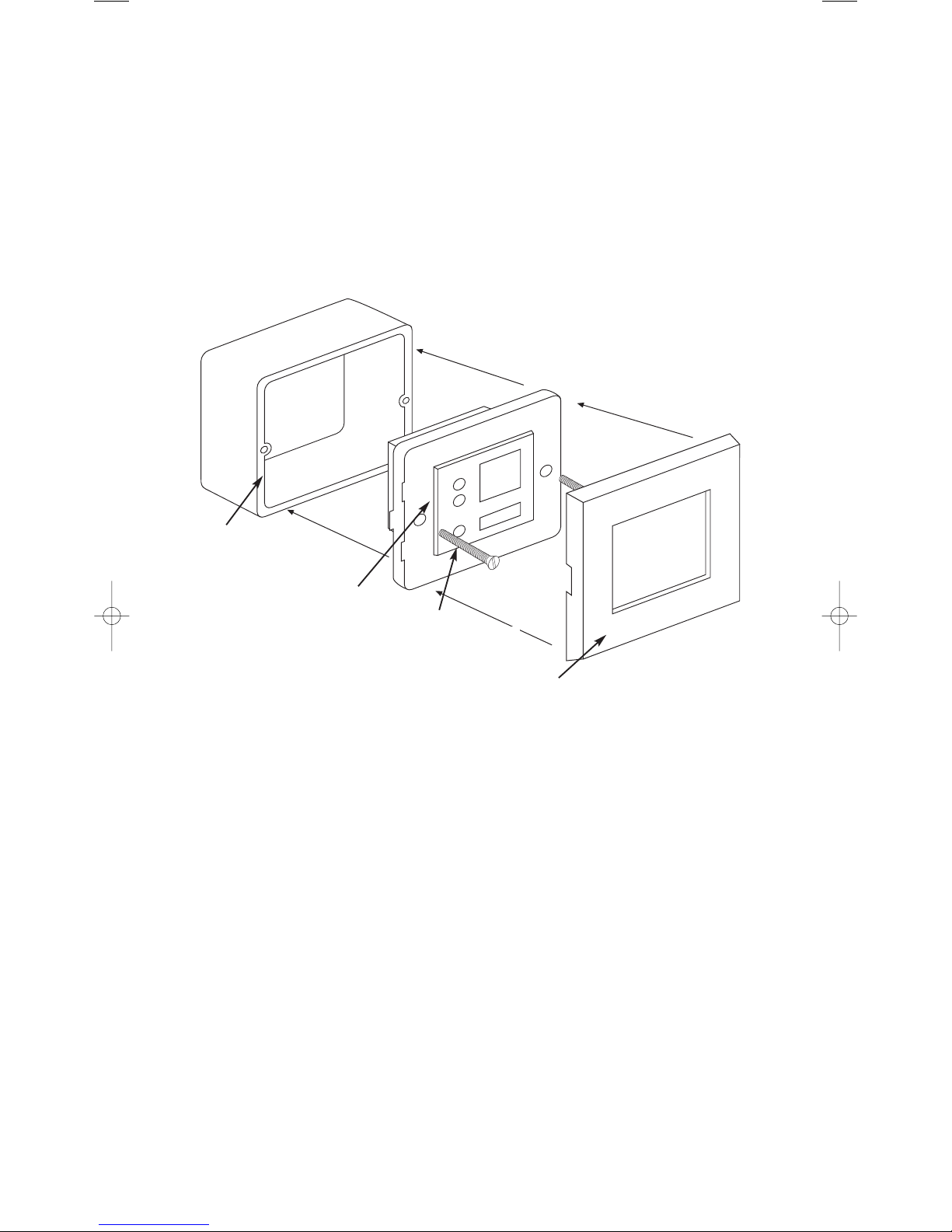
2.5.5 FITTING KMM MODULE INTO BACK BOX AND WALL PLATES.
1) Clip module into grey mounting frame, as shown.
2) Make all necessary wire connections to module.
3) Screw in to wall box.
4) Clip on System 45* facia plate.
*System 45 and Sistema 45 are trade marks of Hamilton Ltd. England and Ave Spa Italy respectively. Alternative
versions of mounting plates and facias are available to fit a wide variety of mainland European back-boxes including
the round type - please ask your distributor for details.
A very wide variety of System 45 facias are available in numerous colours and finishes, ask your dealer for details.
Installation
MusiQ User Instructions
“MK TYPE”
45mm DEEP BACK BOX ( not supplied)
GREY MOUNTING FRAMES
KMM KEYPAD
SYSTEM45 RANGE FACIA
09
Installation
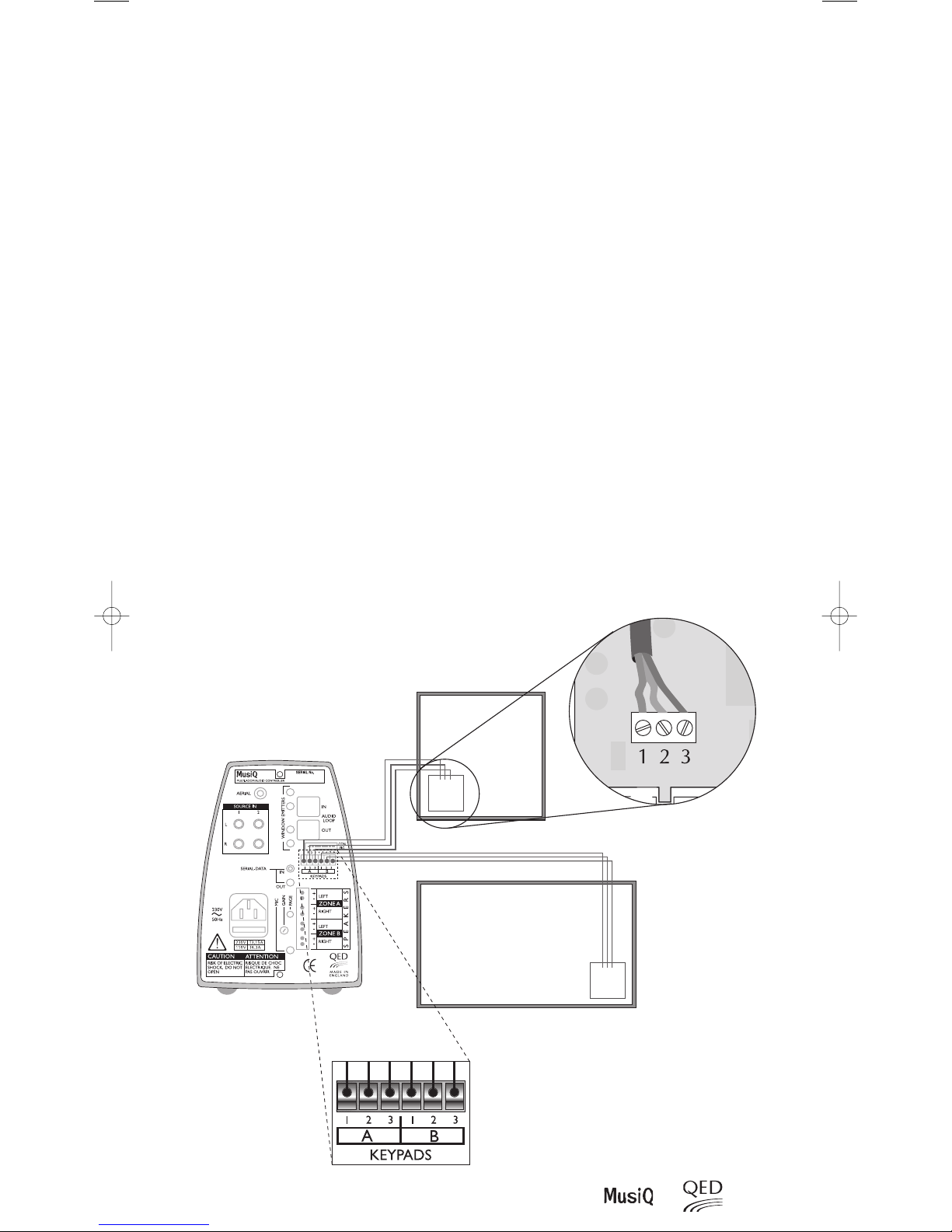
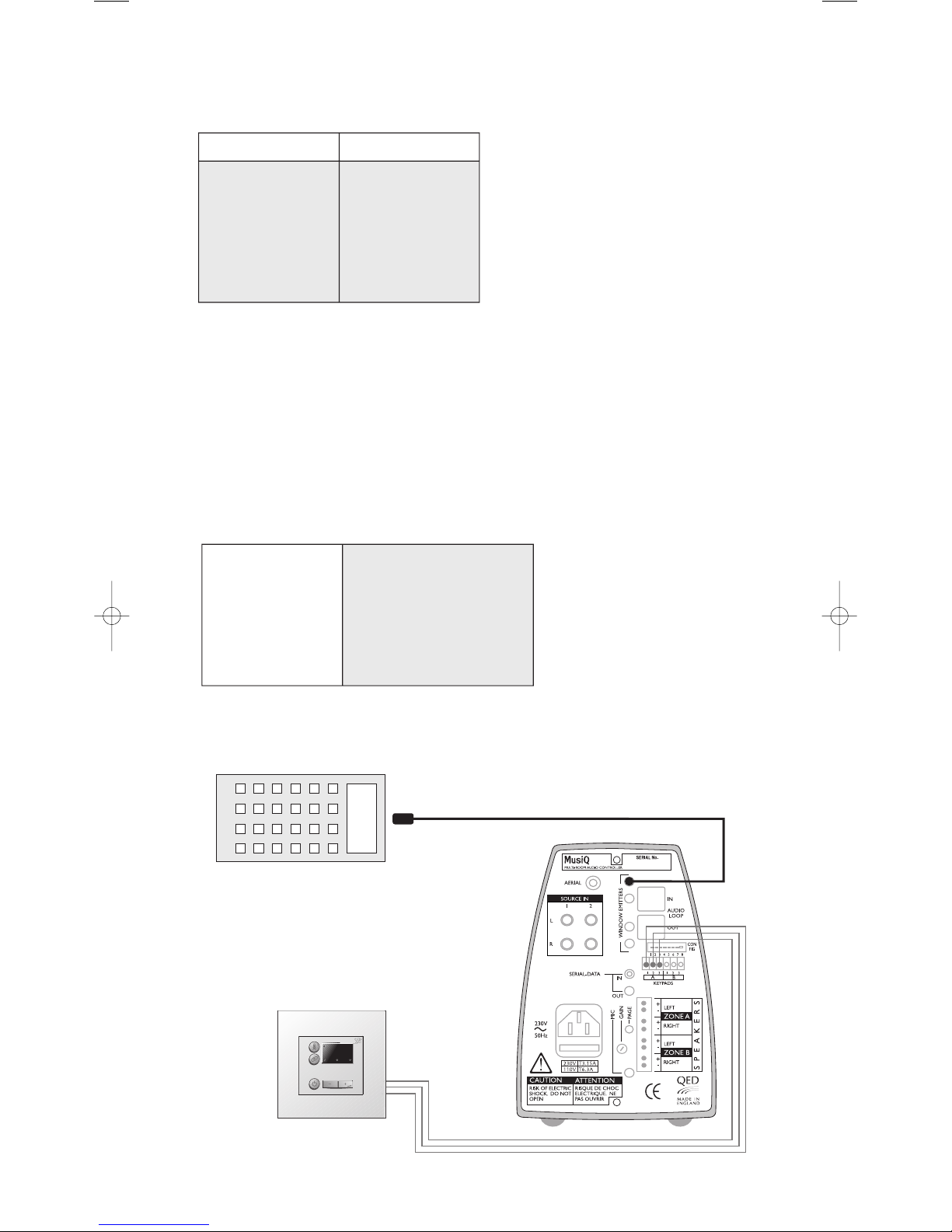
2.5.6 KMM KEYPAD/SENSOR CONNECTIONS
When using KMM Keypad/Sensors, route a three core cable (telephone cable is ideal for this purpose) from each remote
Zone to the rear of the MusiQ and connect as follows (see diagram below).
Note: The 6-way connector plug that locates into the Keypad socket at the rear of the MusiQ is inserted UPSIDE DOWN (Screws facing
downwards). Remember this when wiring the plug as the connections will be reversed when the plug is turned through 180°.
Do not take any notice of the 1 embossed on the 6-way connector plug.
Setting the KMM Keypad Module:
At the rear of each KMM Keypad you will see two small two-way switches at the rear of the unit.
To configure the Keypad to the correct Zone, set the switch as follows:
Keypad for Zone A - Switch 1 to OFF
Keypad for Zone B - Switch 1 to ON
To Enable or Disable display LEDs
Switch 2 is normally not used
ON - LED display active
OFF - LED display NOT active
Note: The purpose of this switch is to disable the LED display on the KMM when connecting to a MusiQ RFS. With these MusiQ controllers any
control function issued from the front panel controls will not be reflected by the LED display on the KMM and hence the KMM will display
incorrect information. In this case disable the LED display to avoid confusion.
The KMM is supplied with a choice of button caps to enable selection of the most appropriate input labelling. The
buttons are ‘1’ & ‘2’to match the front panel source controls of the RFS and also “Music”, “Video”, “CD” and “Tuner”
symbols. The “Music” symbol is ideal for a MusiQ input that is connected to a Tape or Auxiliary Output.
Rear view of KMM Keypad
KMM Keypad
ROOM TWO
ROOM ONE
KMM Keypad
123
123
10
MusiQ User Instructions
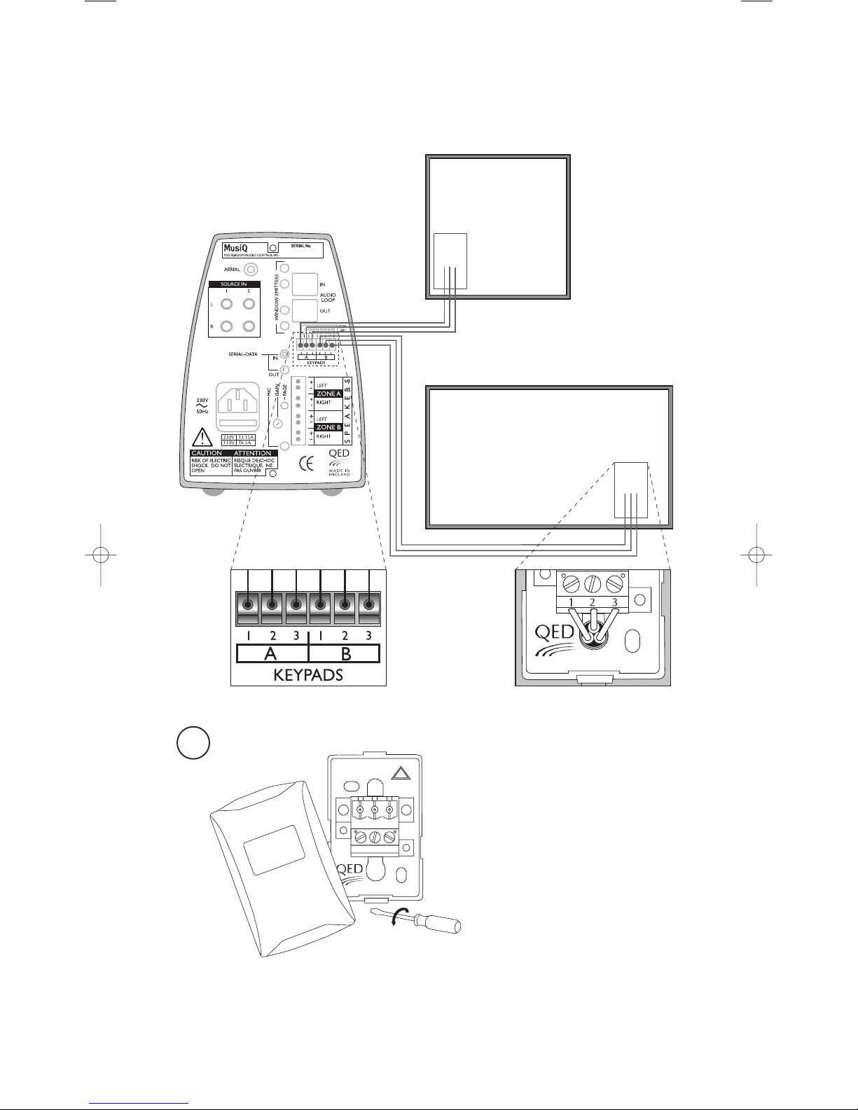
2.5.7 RF HANDSET DOCKING PORT
To use the infra-red relay feature of the RF handset, route a three core cable (telephone cable is ideal for this purpose)
from each docking port to one of the Keypad sockets at the rear of the MusiQ.
Connect as follows:
Installation
1
REMOVE DOCKING STATION COVER
LEVER OFF COVER WITH SMALL FLAT
BLADED SCREWDRIVER
Docking Station
ROOM ONE
Docking Station
ROOM TWO
123
123
123
11
Installation
2.6 CONNECTING A MICROPHONE
If using a microphone, ensure that it is fitted with a 3.5 mm jack plug. Insert the jack plug into the MIC socket at the
back of the MusiQ. If the microphone also has a contact-switched (ON/OFF) 2.5 mm Jack, this should be inserted into
the PAGE socket.
Note:ONLY Mono Microphones should be used.
Always ensure that plugs are fully inserted into their sockets.
If the MIC volume is too high, adjust the MIC Gain Control at the rear of the unit using a flat bladed screwdriver.
WARNING:
Ensure that the gain is not set too high. If any distortion is noticed when using the microphone then reduce the gain
until the distortion is removed.
2
3
TERMINAL NUMBERING
FIX TO WALL USING SCREWS
SUPPLIED AND REPLACE COVER
DOCKING PORT
1) Place the Docking Station back plate into the desired
location and mark the hole positions.
2) Using a 5mm masonry drill bit, drill two holes 35mm
deep at the marked positions.
3) Insert the rawl plugs flush to the wall surface.
4) Wire the connector as detailed in the above diagram.
5) Secure the back plate into position using the screws
provided. Do not overtighten.
6) Affix the cover by locating the top edge and clipping the
bottom into place.
MICROPHONE GAIN CONTROL
PAGE CONNECTION
MICROPHONE
AUDIO
2.5mm Jack Plug
3.5mm Jack Plug
12
MusiQ User Instructions
3 CONFIGURING THE SYSTEM
MusiQ will work straight out of its box, however there are a number of settings that can be adjusted by altering the
CON FIG switches at the rear of MusiQ.
Note: It is particularly important to configure the address switches correctly when using more than one RFS MusiQ.
Installation, Configuring the System
2.7 FITTING WINDOW EMITTERS
In order for the MusiQ to control the source equipment, either by the embedded functions or the I.R. Relay, Window
Emitters must be fitted. Each Window Emitter has a lead approximately 1.5m long and is fitted into MusiQ by means
of a 3.5mm Jack Plug. The small emitter LED fits to the front of the source component by means of a sticky pad. Correct
positioning of the emitter should be checked before being attached, by sending codes through a KMM module or using
the embedded control commands from the front panel or RF handset.
3.1 CONFIGURATION SWITCH SUMMARY
ROOMLINK INFRA RED WINDOW EMITTER ATTACHED TO
IR WINDOW ON SOURCE EQUIPMENT
SOURCE EQUIPMENT
SOURCE EQUIPMENT
Configuration Switch Configuration Switch
Up = ON
Configuration Switch
Down = OFF
Switch No.1
Switch No.2
Switch No.3
Switch No.4
Switch No.5
Switch No.6
Switch No.7
Switch No.8
Paging inhibit
Active EQ sound
Enhancement Zone A
Active EQ sound
Enhancement Zone B
Master/Slave
Party Mode
MusiQ Address 1
(Used only on RF model)
MusiQ Address 2
(Used only on RF model)
MusiQ Address 2
(Used only on RF model)
Only Page Zone A
Enhanced Bass
& Treble
Enhanced Bass
& Treble
MusiQ is Master
Unit in Party Mode
Paging Active in
Zone A & B
Flat Frequency
Response
Flat Frequency
Response
MusiQ is Slave unit
Zone A & B work
independently
13
Configuring the System
3.1.1 SWITCH 1 - PAGING INHIBIT
When using MusiQ with a microphone, you may only want the announcement to be broadcast over one zone. By
setting the switch to ON, only Zone A will relay microphone announcements.
3.1.2 SWITCHES 2 AND 3 - ACTIVE EQ SOUND ENHANCEMENT
When using very small speaker systems or low cost ceiling speakers you should set the Active EQ sound enhancement
feature ON in the appropriate Zone/s to give a fuller and more powerful sound. Experiment to decide which switch
position gives the best results in your environment.
Note: When resetting the Active EQ sound enhancement switches you must turn the mains power Off and then On for the new settings to take
effect.
3.1.3 SWITCH 4 - SLAVE OR MASTER
When using a single MusiQ switch 4 should always be set to Master (ON).
When using multiple MusiQs it is possible to control all units from a single keypad. To do this, switch 4 on all units
other than the Prime MusiQ, must be set to Slave (OFF). This limits the units communication to the SDB Serial Data
Bus only.
There are many different configuration options; refer to section 3.2 for further details.
Note: You can Mix RFS and IS units together if you wish. When constructing a large system where control is required from a central location, it is
recommended that a Master RFS unit be used in conjunction with IS units set in Slave mode. This gives the most economical solution.
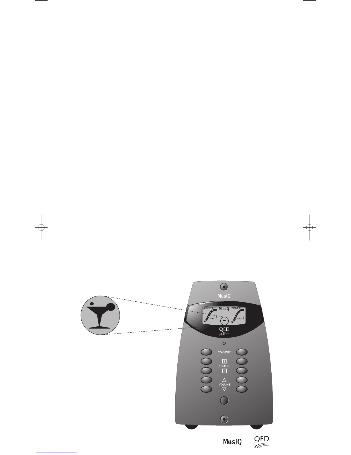
3.1.4 SWITCH 5 - PARTY MODE
MusiQ can be configured to operate Zone A and Zone B simultaneously from the RF handset, KMM Keypad or front
panel control by setting switch 5 to ON. This means that if either a Zone A or Zone B command is issued both zones
will respond, selecting the same source and volume level. This is particularly useful when you want the same sound
in all zones. When party mode is selected, the standby LED will glow AMBER when both zones are in standby. To enter
party mode on the RFS units depress both standby buttons simultaneously when both zones are in standby. If the unit
is an RFS, the display will show a Party Cocktail glass when the unit is active. To exit party mode depress both standby
buttons simultaneously when in standby.
14
MusiQ User Instructions
Configuring the System
3.2 CONFIGURING MULTIPLE MUSIQ RFS
When using the RFS version of MusiQ it is important that the address switches of both the MusiQ and RF handsets are
set to the same settings. When using more than one MusiQ RFS, it is advisable to set each MusiQ to a different address.
The factory defaults will enable the use of one MusiQ RFS without the need to change the address switch settings on
the MusiQ or RF Handsets. If more than one MusiQ RFS is being used, you are advised to follow the table below:
Note: Switch 1 at the rear of each handset determines which Zone is controlled, as follows:
Handset for Zone A Switch 1 ON
Handset for Zone B Switch 1 OFF
You can use as many RF handsets as you want to control each zone. If additional handsets are required, these can simply be set to the required
address of the MusiQ RFS and Zone you want to control.
RF HANDSET ADDRESS SWITCHES
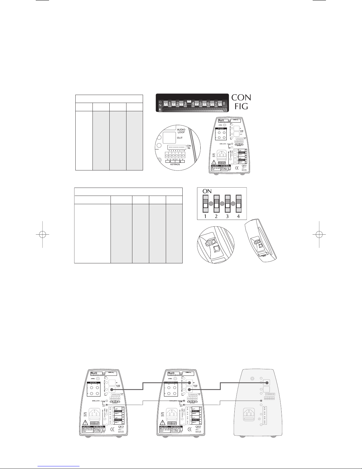
3.3 CONNECTING MULTIPLE MUSIQ USING SERIAL DATA LEAD AND
AUDIO PASS THROUGH CABLE
If one or more slave MusiQ’s are connected to a master, a serial data lead is used to relay the control code from from
the master to the slave. The audio pass through cable is used to pass the audio signal from the master to the slave/s.
Connect as per the following diagram:
If required a 3rd MusiQ can
be connected as shown
RFS CONTROLLER ADDRESS SWITCHES
MUSIQ
Switch 6 Switch 7 Switch 8
MusiQ 1 OFF OFF OFF
MusiQ 2 OFF OFF ON
MusiQ 3 OFF ON OFF
MusiQ 4 OFF ON ON
MusiQ 5 ON OFF OFF
MusiQ 6 ON OFF ON
MusiQ 7 ON ON OFF
MusiQ 8 ON ON ON
HANDSET
Switch 1 A/B Switch 2 Switch 3 Switch 4
MusiQ 1 Handset A/B ON/OFF OFF OFF OFF
MusiQ 2 Handset A/B ON/OFF OFF OFF ON
MusiQ 3 Handset A/B ON/OFF OFF ON OFF
MusiQ 4 Handset A/B ON/OFF OFF ON ON
MusiQ 5 Handset A/B ON/OFF ON OFF OFF
MusiQ 6 Handset A/B ON/OFF ON OFF ON
MusiQ 7 Handset A/B ON/OFF ON ON OFF
MusiQ 8 Handset A/B ON/OFF ON ON ON
4 TROUBLESHOOTING
If you are having problems with the installation DON’T PANIC. It does not necessarily mean that the equipment is
faulty. Please follow the following chart to help you diagnose faults and remedy them quickly.
PROBLEM SOLUTION
15
Troubleshooting
IS THE UNIT
CONNECTED TO THE
MAINS SUPPLY
?
IS THE FRONT
PANEL LED ON
DO THE FRONT PANEL
CONTROLS WORK
(RFS)
IS THE DISPLAY ON THE
MIC SYMBOL SHOWN
CONSTANTLY
?
DOES THE MUSIQ
OPERATE FROM A KMM
KEYPAD
?
DOES THE RF
HANDSET WORK
?
DO BOTH RF HANDSETS
CONTROL THE SAME
ZONE
?
DO BOTH KMM KEYPADS
CONTROL THE SAME
ZONE
?
DO BOTH ZONES
OPERATE TOGETHER
WHEN YOU WANT
THEM TO OPERATE
INDEPENDENTLY
?
DOES MORE THAN ONE
MUSIQ RFS OPERATE AT
THE SAME TIME
?
NO
NO
NO
YES
NO
NO
YES
YES
YES
NO
Connect the mains cable and ensure that both the mains switch on
the front of the MusiQ and at the wall socket are ON.
Check the mains fuse located at the rear of the MusiQ
and also in the main plug.
If the unit is not a ‘slave’ ensure that switch 4
of CON FIG is UP = ON
Disconnect the plug from the Mic page socket.
It may be constantly shorted.
If MusiQs are daisy chained ensure that it is not another
unit that has its Mic socket shorted.
If there is no LED illumination on the keypads re-check the
corrections. They may be reversed. Check also for breaks in the data
cable. Connect the KMM to the MusiQ with a short length of data
cable to confirm fault/operation. If the unit is not a ‘slave’ ensure that
switch 4 CON FIG is UP = ON.
Ensure that the handset battery is ok and inserted correctly.
Check that the handset address and MusiQ address match.
Check the aerial is connected to the musiQ.
Ensure that switch 1 on the RF Handset is set differently on each.
ON/UP=Zone A, OFF/DOWN=Zone B.
Ensure that switch 1 at the rear of each keypad is set differently.
Ensure that switch 5 of CON FIG is set OFF = Down
If two MusiQ RFS units operate from a single handset you need to
change the address of one of the MusiQs.
This is done by altering switches 6, 7 and 8 of the CON FIG to a
different setting (see section 3.2).
YES
YES
YES
YES
YES
YES

16
MusiQ User Instructions
Technical Specification, Operation
5 TECHNICAL SPECIFICATION
Power Output into 5 Ohms @ 1 kHz 22 W at 0.1%THD One channel driven.
Power Output into 5 Ohms @ 1 kHz 20 W at 1.0%THD Two channels driven.
Recommended Speaker Impedance: 4 - 16 Ohms
Frequency Response: 20 Hz to 20 kHz ±0.5dB
Frequency Response of +2.75 dB @ 100 Hz relative to 0 dB at 1 kHz
Active EQ Sound Enhancement: +0.55 dB @ 5.3 kHz relative to 0 dB at 1 kHz
Distortion THD 1 kHz at 10 W <0.04% One channel driven
(measured into 5 Ohms)
Channel Separation: >80 dB @1 kHz between Left & Right Channels.
>90 dB @1 kHz between Source 1 & Source 2 Inputs.
Input Sensitivity: 370 mV RMS into 100k Ohms for full output at maximum volume
5.1 Microphone Input
Input Impedance: 680 Ohms
(suitable for microphones with a nominal impedance of 200-1k Ohms)
Gain Control Range: 45 dB
Frequency Response: 40 Hz to 20 kHz ±0.8dB
5.2 General
Weight: 3.5 kg
Power Consumption: 120 W
Battery (MusiQ RF/RFS Handset only) Type MN21, GP23A or VR22 (Available from all good photography shops)
Supported Brands RC-5 - A Philips code set used by many other companies including
Arcam, Linn and Marantz
Caution: Some manufacturers who claim to use this code set do not follow the correct
protocol and therefore their equipment may not respond correctly, or at all.
Denon Caution: MusiQ will operate tuners with direct preset selection only.
Check with dealer first.
Pioneer, Sony, Yamaha
6 OPERATION
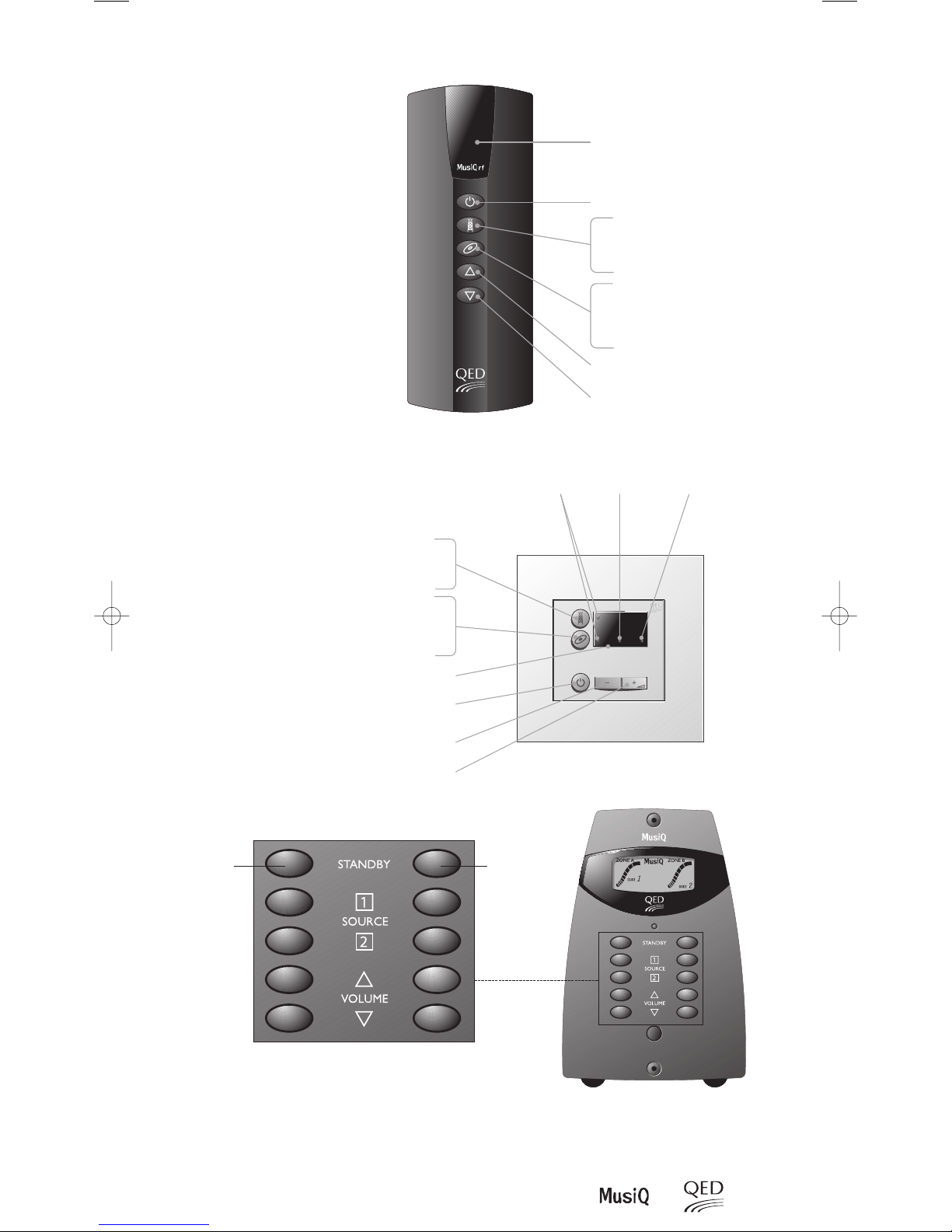
6.1 MUSIQ FRONT PANEL CONTROLS (RFS MODELS)
Two columns of buttons on the front panels of the RFS models enable control of both Zones directly from the unit. The
left hand buttons control the functions of Zone A and the right hand buttons control the functions of Zone B.
1. Pressing the Source 1 (tuner) or Source 2 (CD) button when the unit is in Standby will turn the zone ON and select
the appropriate source. The volume will increase to a low listening level (see note below), and both the display and
buttons will illuminate.
2. Pressing the Standby button will return the zone to standby. If both zones are active and one is switched into standby
the other zone will remain ON. The display will remain active until both zones are in standby.
Note: When either Zone is returned to standby the Volume level is remembered, providing the unit is not switched
OFF.
This means that the volume will return to the previous listening level when the zone is re-activated on
subsequent occasions.
3. Pressing the Volume Up button will increase the listening level in the zone. The LCD volume bar graph display rises
to indicate the level reached.
4. Pressing the Volume Down button will decrease the listening level in the zone. The LCD volume bar graph display
falls to indicate the level reached.
6.1.1 ENTERING PARTY MODE
In normal operation both zones operate independently. Whether you are using a single MusiQ or multiple MusiQs it
is sometimes desirable to have all zones selected to the same source, listening at the same volume level. To enter this
mode of operation, if using a MusiQ RFS, ensure that both zones are in standby and press both Standby buttons (Zone
A & B) together until the RED Standby LED turns AMBER. The unit is now in Party Mode and using either Zone A or
Zone B controls will operate both zones. To exit party mode repeat the above procedure.
Note: The setting of CON FIG switch 5 (Party mode) determines whether Party mode is automatically ON or OFF when
the unit is powered ON from the mains. This setting can always be overridden by the front panel controls on the RFS
models. Once the unit is disconnected from the mains supply the CON FIG switch setting will override any alternative
setting when mains power is re-applied.
If a slave is connected to a master RFS then enabling party mode from the front panel controls will also alter the mode
on the slave units.
6.2 SOURCE CONTROL COMMANDS
The embedded key functions built into the MusiQ software enable easy operation of the main control functions for
many tuner and CD source components (see Section 2.5.2). The available control functions are as follows:
• Tuner Channel Skip - If you wish to skip preset channels, simply depress the Source 1 key on the front panel of
the RFS model (or on the remote RF handset/KMM keypad) until you hear the channel skip (approximately 1.5
seconds) and then release it. Only one preset is skipped; to skip further presets you must repeat the procedure for
each preset.
• CD Play - To start the CD playing, depress the Source 2 key on the front panel of the RFS models (or on the remote
handset/keypad) for approximately 3 seconds and then release it. After a few moments you should hear the CD
playing.
• CD Track Skip – To skip tracks on a CD, hold down the Source 2 key on the front panel of the RFS models (or on the
remote handset/keypad) for approximately 1.5 seconds and then release it. Repeat the procedure to skip further tracks.
• CD Disc Skip - If you are using a Multi Disc CD player and you wish to skip to the next disc, double click of the
Source 2 key on the front panel of the CM or RFS models (or on the remote handset/keypad). The button should be
depressed and released twice within a period of 0.5 seconds.
17
Operation
ZONE A
ZONE B
STANDBY LED
Press for 1.5 seconds
Note: Once the first 8 presets are skipped the tuner will be
returned to preset 1 on the next preset skip command.
Press for 3 seconds
Press for 1.5 seconds
Press and Release within a period 0.5 seconds
Note: It is advisable to try all the above functions initially whilst you can see the source equipment
operating. This will help you to obtain a feel for the button operation that issues each command.
Operation
6.3 USING A PROGRAMMABLE REMOTE CONTROL WITH KMM MODULES
It is possible to teach high quality learning handsets the 10 control commands. These commands are:
NOTE: The following IR learning handsets have been tested and work:
Marantz RC-1200
Marantz RC-2000
Marantz RC-5000 (also Philips Pronto)
ARCAM CR-9000
Procedure
1) Connect an IR window emitter to the MusiQ controller
2) Connect a KMM module to the Zone A of Zone B keypad input at the rear of the MusiQ.
3) Ensure that switch 1 of the KMM module is set to Zone A.
4) Position the IR window emitter a few inches away from the programmable handset IR receiver window.
5) There are 5 commands to learn for Zone control. (See note below)
6) Ensure that switch 1 of the KMM module is set to Zone B.
7) Repeat the above steps 4 & 5 for Zone B operation
Note: Please refer to the programmable handset manual for specific instructions on how to learn codes.
18
MusiQ User Instructions
LEARNING HANDSET
WINDOW EMITTER
KMM KEYPAD
‘ZONE A’ Commands ‘ZONE A’ Commands
Select Source 1
Select Source 2
Standby
Volume Up
Volume Down
Select Source 1
Select Source 2
Standby
Volume Up
Volume Down
Select Source 1
Select Source 2
Standby
Volume Up
Volume Down
By pressing Button 1 on the KMM
By pressing Button 2 on the KMM
By pressing Standby on the KMM
By pressing Volume Up on the KMM
By pressing Volume Down on the KMM
Operation
19
Important Notice
These functions are only possible
when using suitable products from
supported brands (see specifications
for list of brands).
The infra-red relay feature of the
Docking handset can only be used
when the handset is docked and the
Docking Port suitably wired.
MusiQ RFS front panel controls
These enable both zones to be controlled directly from the unit. The functionality is the same as the
RF handset detailed above. In addition, the LCD display conveys comprehensive information about
the status of both zones.
Zone “B”
Zone “A”
6.4 KEY FUNCTIONS
Infra-red receiver window
Switches zone off
Increase volume
Decrease volume
*Double press will skip the next disc.
Press once switches zone on and selects
Tuner (Source 1)
Press and hold down will skip radio stations
(8 stations loop)
Press and hold down for 3 seconds, will
switchzone on and send play command* to
C.D.player (Source 2)
Press and hold down for 1.5 seconds will
skip to next track
Press once switches zone on and
selects Tuner (Source 1)
Press and hold down will skip radio
stations (8 stations loop)
Press and hold down for 3 seconds, will
switchzone on and send play command* to
C.D.player (Source 2)
Press and hold down for 1.5 seconds will
skip to next track
Infra-red receiver window
Switches zone off
Decrease volume
Increase volume
*Double press will skip the next disc.
Source selected Standby indication
Infra-red receive
indication
 Loading...