

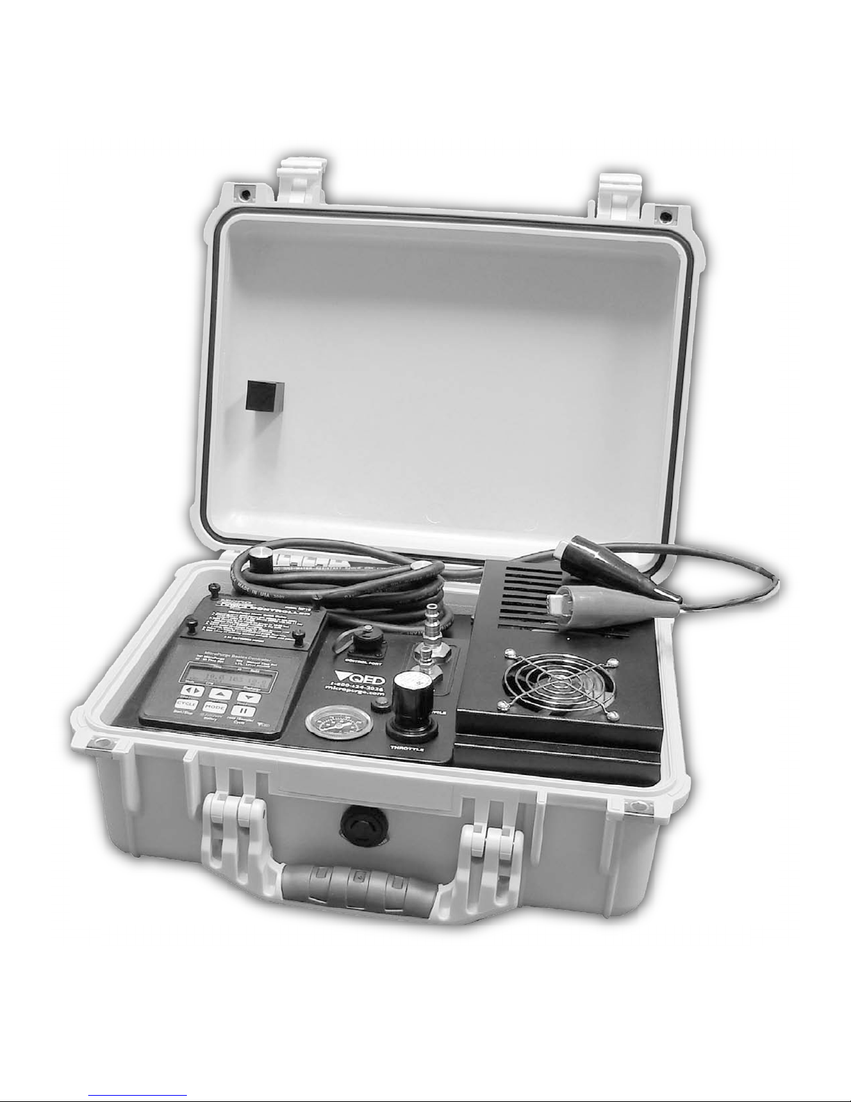
QED MP50 Instruction Manual

O
U
a
MODEL
sics
CONTROLLER/COMPRESSOR
Instruction
MP50
PATENT PENDING
Manual
Part No. 95258 2-15-10
P.O. Box 3726 Ann Arbor, MI 48106-3726 USA
1-800-624-2026 Fax (734) 995-1170
info@qedenv.com www.qedenv.com
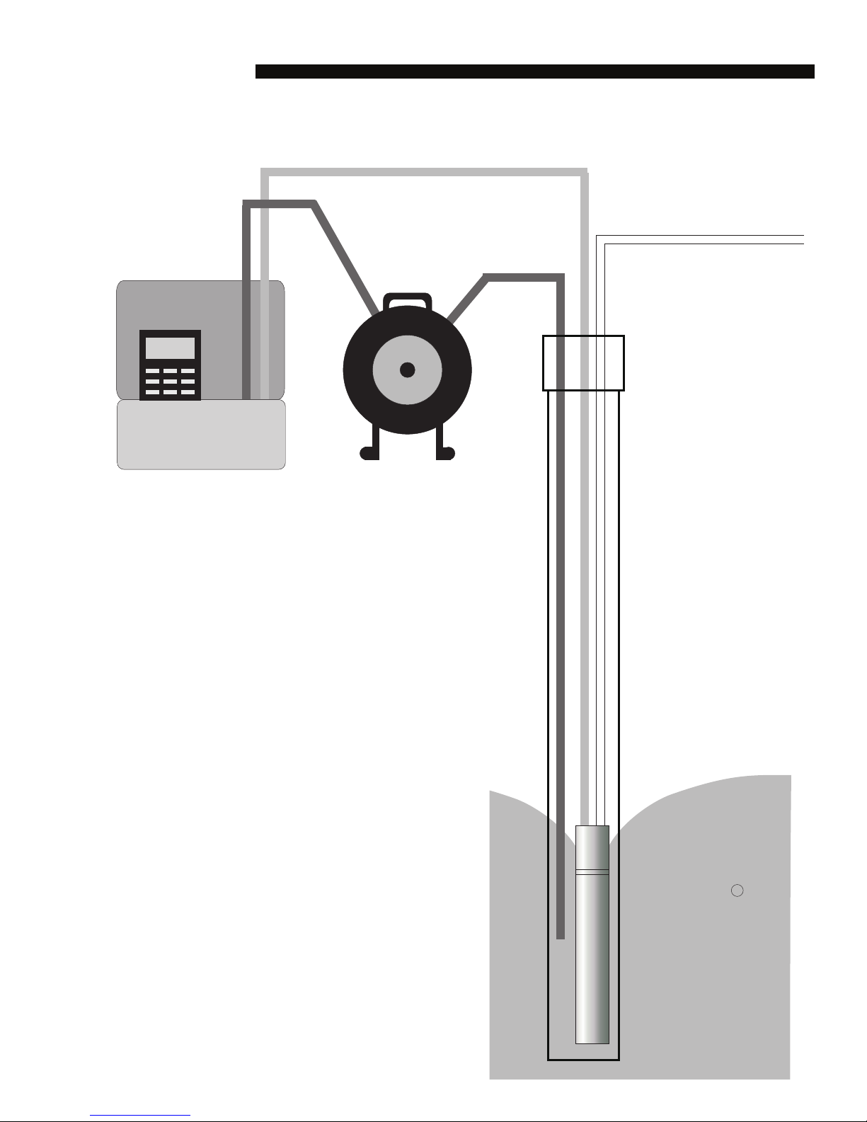
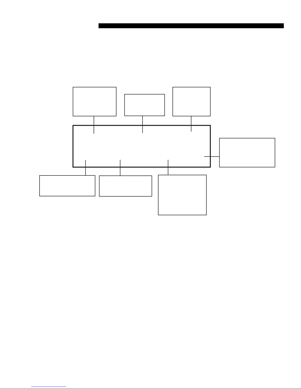
MP50 Basic Setup
Pump Air Supply
Pump Discharge
Well
Cap
MP50
Controller
Optional
MP30 Drawdown
Meter
Tubing
Well Wizard
Bladder
Pump
R

Contents
Topic
Page
Safety Warnings
Conventions and Diagrams
Introduction / Quick-Start
Bladder Pump Operation in Low-Submergence Applications
Turning the MP50 On
Opening Display
MicroPurge Mode
Using CPM
1
1
4
6
7
7
8
8
Sampling
Use with the MP30 Level Sensing Water Level Meter
ID Mode
User Time Set (MN) Mode
MP50 Battery
Troubleshooting
MP50 Specifications
QED Service Contacts
QED Warranty
10
11
14
15
16
17
18
19
20
Appendix 1 ID Data Table
21
Safety Warnings
Safety warnings
Compressed air - Use caution when working with compressed air or gas. Compressed gas
cylinders are under extreme pressure and can cause unrestrained hoses to whip about dangerously. Do not over pressurize your controller. Failure to operate the controller within the pressure limits could result in failure. Read all operating instructions before operating the MP50
controller.
Warning - Do not disassemble the pneumatic pump while it is connected to a compressed gas
source. Dangerous pressures could cause injury.
Diagrams and Conventions used in the Text
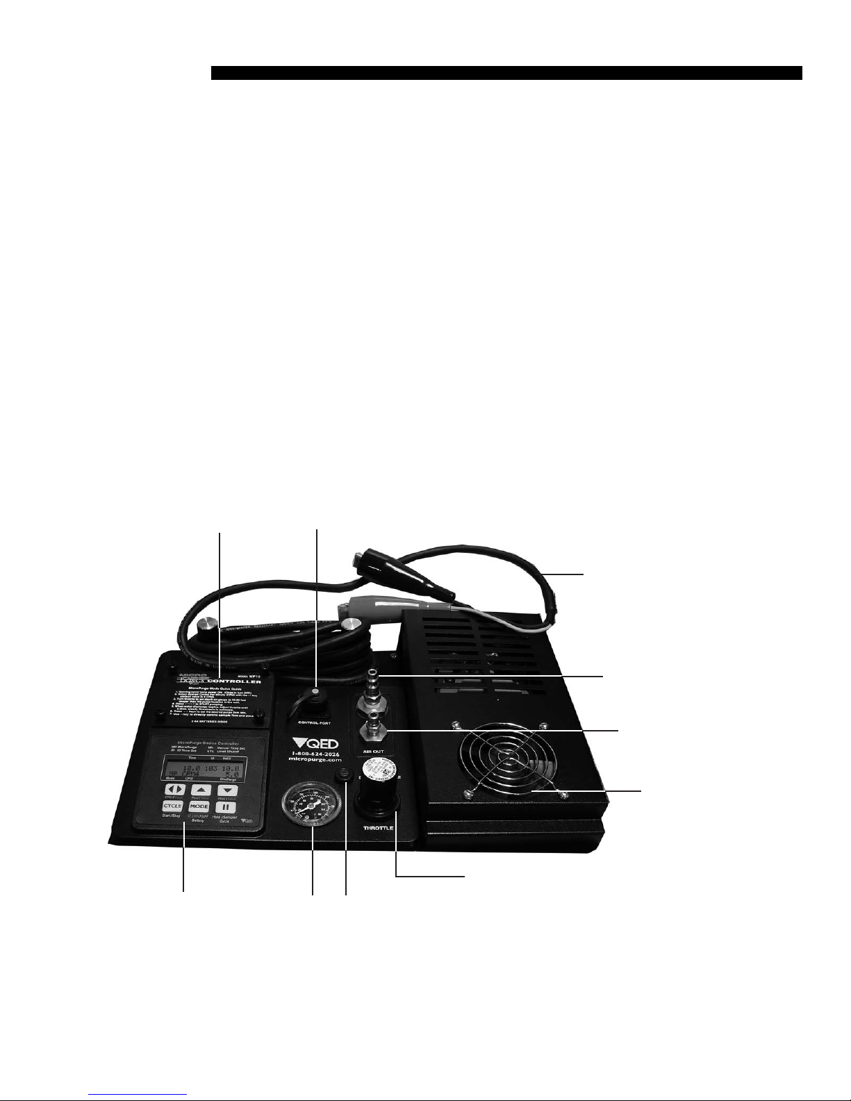
MP50 Panel Layout:
Battery
Cover
MP50 Control
Keypad and
display
Connector for optional
MP30 Drawdown Control
Pressure
Gauge
Discharge
cycle
indicator
Battery
Connectors
Compressed
Gas Source
Connection
Controller
To Pump
Connection
Compressor
Fan
Flow
Throttle
1
Diagrams / Conventions
Diagrams And Conventions Used In The Text (Cont.)
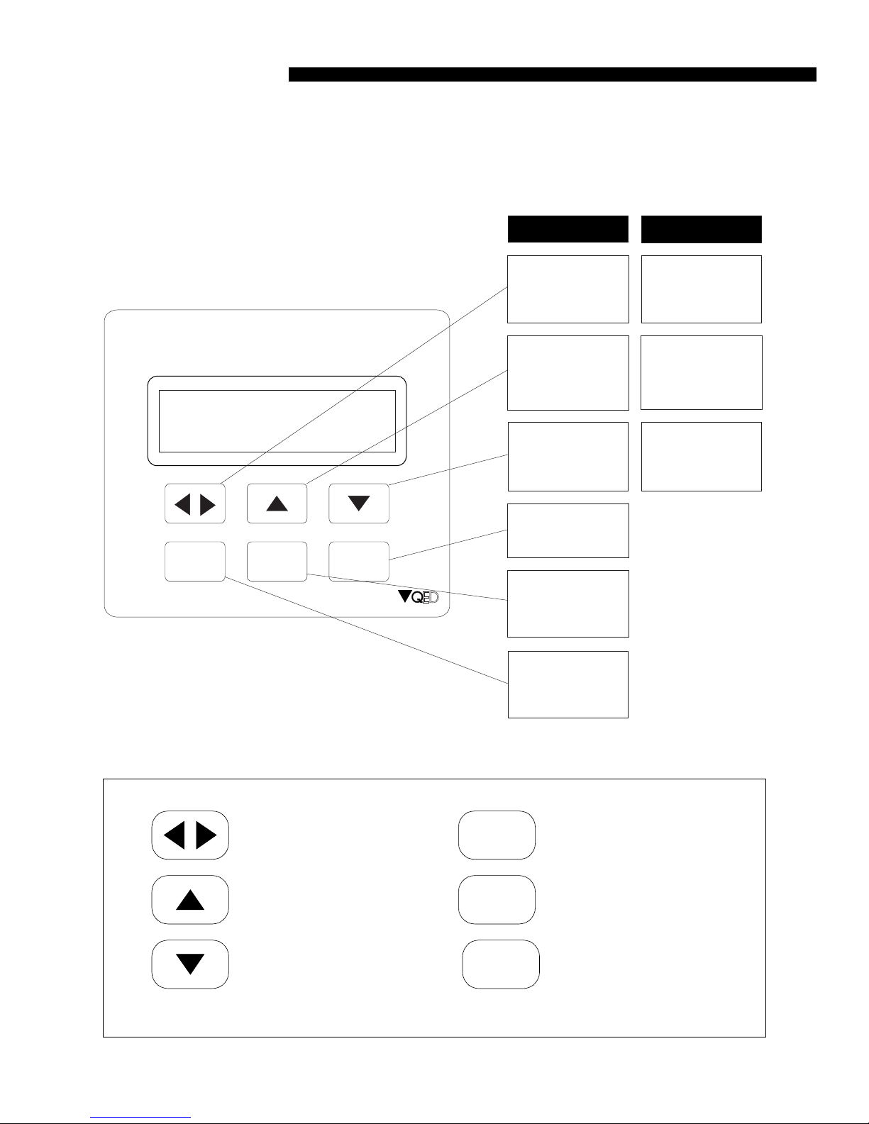
MP50 Control Keys:
MicroPurge Basics Controller
MP Micro Purge
ID ID Time Set
Time
00.1
MP
CPM4 >05.0
Mode CPM
CPM/Value Flow/Value Flow/Value
CYCLE
Start/Stop
MN Manual Time Set
LVL LevelShutoff
ID
103
Discharge
MODE
ID/MN/MP/
Battery
Refill
10.0
I I
Hold/Sample
/Cycle
D E
In MP Mode
Cycle Per Minute
key - Changes
cycle per minute
Faster key Speeds up flow
Slower key Slows down
flow
Pause key Pauses flow for
sampling
Mode key -Selects
the operation
mode. Also battery
check
In Other Modes
Scrolls cursor
Changes a value
at the cursor
location
Changes a value
at the cursor
location
CPM Button (also scroll for
item selects)
UP Button, faster pumping
(also increase item)
DOWN Button, slower
pumping (also decrease
item)
2
Cycle key -Selects
Start and Stop of
pump cycling
CYCLE
MODE
I I
CYCLE Button
MODE Button (also battery
check)
PAUSE Button (also
manual sample)
Diagrams / Conventions
Diagrams And Conventions Used In The Text (Cont.)
MP50 Display:
Time
remaining
in the cycle
00.1
MP CPM4
The mode the
controller is in
ID for time
settings
103 10.0
Cycles per
minute setting
Refill time
setting in
seconds
>05.0
Indicates if
pump is
Refilling or
Discharging
Discharge time
setting in
seconds
Abbreviations:
CPM
MP
ID
HELD
MN
BAT
LVL
>
Cycles Per Minute
MicroPurge Mode
ID Time Set Mode
Held In A Cycle
Manual Time Set Mode
Battery
Level Pause
Indicates Refill Or Discharge Cycle
3

Introduction / Quick Start
Introduction / Quick Start
Introduction: The MP50 Micro Purge Basics Controller/Compressor is used to operate QED
Well Wizard™ bladder sampling pumps to purge and sample ground water. The MP50 has
specific design features to make MicroPurge ™ sampling easier. These features include:
MicroPurge Mode Operation Simple Increase / Decrease keys allow you to easily set
the flow rate you need for each well.
ID Time Set Mode Operation Quickly recalls pre-determined settings for each well by
specifying a 3-digit ID.
Level Delay Interface The controller plugs into the optional MP30 MicroPurge Drawdown / Water Level Meter to provide direct feedback of well drawdown and to pause
pump operation until the level recovers.
The optional MP30 MicroPurge Drawdown / Water Level Meter plugs into the MP50 to provide water level feedback. The MP30 uses a standard conductivity probe to detect the
ground water surface and a marked tape allowing the user to measure the depth. When the
meter is set in MicroPurge mode, the probe is lowered a specific distance below the static
water level and fixed in this position. During well sampling if the water level drops below
the user-set probe position, the MP50 is paused which prevents further drawdown by the
pump. Once the level recovers the MP50 begins pump operation again, starting in the pump
refill cycle. Use of the MP50 with the MP30 is detailed later in this manual.
Insert Batteries: Remove the battery cover on the top of the MP50. Insert 3, AA alkaline batteries into the battery holder and carefully replace the holder in the carrier. Replace the
battery cover and tighten the 4 screws. Batteries should last for about 6-8 weeks of typical
full-time field use. If the MP50 will be stored longer than about 3 months, the alkaline batteries
should be removed to prevent leakage.
4
 Loading...