

Leaders in Environmental Compliance Products
OPERATIONS
Au
to
Pump
+
MANUAL
ATEX Version
602418-02 (doc # 602418 ) (Rev 12/10/12)
DURABLE,
DEPENDABLE,
& DELIVERS
AutoPump Controllerless System
(For 4 inch wells or larger)
1-800-624-2026 (North America Only) (734) 995-2547 - Tele (734) 995-1170 - Fax info@qedenv.com - E-mail www.qedenv.com
QED Environmental Systems - P.O. Box 3726 / 2355 Bishop Circle W. Dexter, Michigan 48130-3726
QED Environmental Systems (West) - 1565 Alvarado Street San Leandro, California 94577-2640
1-800-537-1767 (North America Only) (510) 346-0400 - Tele (510) 346-0414 - Fax
Copyright QED Environmental Systems, Dec. 2012

Patents/Trademarks
The equipment in this manual is protected under U.S. and foreign patents issued and pending:
U.S. Patents:
AutoPump (AP)
"AP" is a Registered Trademark of "QED Environmental Systems"
"AutoPump" is a Registered Trademark of "QED Environmental Systems"
The QED Environmental Systems logo is a Registered Trademark of "QED Environmental Systems"
QED Environmental Systems is a Registered Trademark of "QED Environmental Systems"
5,004,405

Table of Contents
Introduction
Chapter 1: Safety
_________________________________________________
_______________________________
Safety
How to Contact QED
_______________________________
____________________________________________
A Partial List of Safety Procedures
Fire and Explosion Protection
_______________________________
Chapter 2: ATEX Certification Information
ATEX Certifications, Label Detail and Explanation
Chapter 3: Overview
Chapter 4: Equipment
Chapter 5: Installation
Chapter 6: Maintenance
Chapter 7: Troubleshooting & Repairs
_________________________________________
General Specifications
This is How it Works
_______________________________
_______________________________
________________________________________
Unpacking
Equipment List
Single Stage Filter/Regulator
_______________________________
_______________________________
_______________________________
_____________________________
Installation
Hose Bundling
_______________________________
_______________________________
______________________________________
Cleaning Pump Interior
Iron Build-up Cleaning Procedure
_______________________________
__________________________
Troubleshooting
Returning Equipment for Service
Equipment Cleaning Requirements
_______________________________
_______________________________
____________________________________________
_______________________________
_______________________________
_______________________________
_______________________________
1
1
1
2
2
2
3
3
5
5
5
8
8
8
8
9
9
10
13
13
13
20
20
22
22
Pump Specifications
_______
AP4+ Bottom Inlet Long
AP4+ Bottom Inlet Short
AP4+ Bottom Inlet Low Drawdown
AP4+ Top Inlet Long
AP4+ Top Inlet Short
AP4+ Top Inlet Low Drawdown
Terms, Conditions and Warranty
Figures:
Figure 1 -
Figure 2 -
Figure
Figure
Figure
Figure
Figure
Figure
Figure
Figure
Figure
Figure 12 -
Figure 13 -
ATEX Label Detail and Explanation
ATEX Label Location and Appearance
- 3
- 4
- 5
- 6
Examples of Well Caps
- 7
Hose Bundling
- 8
Exploded View of a Bottom-Loading AutoPump AP-4+ (Long & Short)
- 9
Exploded View of a Bottom-Loading AutoPump AP-4+ (Low Drawdown)
Exploded View of a Top-Loading AutoPump AP-4+ (Long & Short)
- 01
- 11
Exploded View of a Top-Loading AutoPump AP-4+ (Low Drawdown)
Exploded View of AP-4+ Lever Assembly
Exploded View of 1-Inch Brass Check Valve
_______________________________
_______________________________
_______________________________
_______________________________
_______________________________
_______________________________
_______________________________
_______________________________
_______________________________
_______________________________
skroW ti woH
_______________________________
metsyS pmuPotuA eht fo weivrevO
_______________________________
_______________________________
_______________________________
_______________________________
_______________________________
stcennoC-kciuQ htiw 06 rotalugeR/retliF egatS elgniS
_______________________________
_______________________________
_______________________________
_______________________________
23
23 - 26
27 - 29
31 - 34
35 - 38
39 - 42
43 - 46
47
3
4
6
7
8
11
12
14
15
16
17
18
19

Introduction
Welcome to QED Environmental Systems’ AutoPump® (AP4+) manual.
To ensure the best operator safety and system performance, it is strongly recommended that the operators read this
entire manual before using the system.
This manual reflects our many years of experience and includes comments and suggestions from our sales and
service personnel and most importantly from our customers. The chapters, their contents and sequence were designed
with you, the user and installer, in mind. We wrote this manual so it can be easily understood by users who may not be
familiar with systems of this type or are using a QED system for the first time.
Safety
Safety has been a cornerstone of our design which has been proven out in building and shipping systems throughout
the world. Our high level of performance is achieved by using quality components, building in redundancies or backup
systems, and not compromising our commitment to quality manufacturing. The net result is the highest quality and
safest pneumatic pump recovery system on the market. We feel so strongly about safety, based on years of working
with the hydrocarbon industry, that it is the first section of all our manuals
How to Contact QED
If for any reason you are unable to find what you need in this manual feel free to contact the QED Service Department
at any time. We encourage you to use following communication methods to reach us at any time:
San Leandro Service Center
1565 Alvarado Street
San Leandro, California 94577-2640
(
(510) 346-0400 — Tele.
(510) 346-0414 — Fax
QED can be reached 24 hours a day
Service Department
QED Environmental Systems
www.qedenv.com
ylnO aciremA htroN — 7671-735 )008
Ann Arbor Service Center
PO Box 3726
Ann Arbor, Michigan 48106-3726
2355 Bishop Circle W.
Dexter, Michigan 48130
(800) 624-2026 — North America Only
(734) 995-2547 — Tele.
(734) 995-1170 — Fax
info@qeden
v.com — E-mail
We welcome your comments and encourage your feedback regarding anything in this manual and the equipment you
have on-site.
Thank you again for specifying QED equipment.
1

Chapter 1: Safety
Safety has been a prime consideration when designing the AutoPump System. Safety guidelines are provided in this
manual, and the AutoPump System safety features are listed below. Please do not attempt to circumvent the safety
features of this system.
We have also listed some possible hazards involved when applying this system to site remediation. Nothing will protect
you as much as understanding the system, the site at which it is being used, and the careful handling of all equipment
and fluids. If you have any questions, please contact the QED Service Department for guidance.
As you read through this manual, you will encounter three kinds of warnings. The following examples indicate how they
appear and lists their respective purposes.
Highlights information of interest.
Note:
Caution:
Warning:
Highlights ways to avoid damaging equipment.
Highlights personal safety issues.
A Partial List of Safety Procedures
WARNING:The air compressor and any other electrical equipment used with this pneumatic system must be
positioned outside of any area considered hazardous because of possible combustible materials.
These safety procedures should be followed at all times when operating QED equipment on or off site, and should
be considered as warnings:
Wear safety goggles when working with the AutoPump System to protect eyes from any splashing or pressure
•
release.
•
Wear chemically resistant rubber gloves, boots, and coveralls when handling the AutoPump and fluid discharge
hose to avoid skin contact with the fluid being removed
•
Point tubing/hoses away from personnel and equipment when connecting or disconnecting.
•
Always ensure that the fluid discharge line is connected before the air line to prevent accidental discharge.
The AutoPump System minimizes the potential for accidents with the following safeguards:
Fire and Explosion Protection
Almost all of QED underground fluid extraction systems are pneumatic. This offers many inherent fire and explosion
protection features.
2
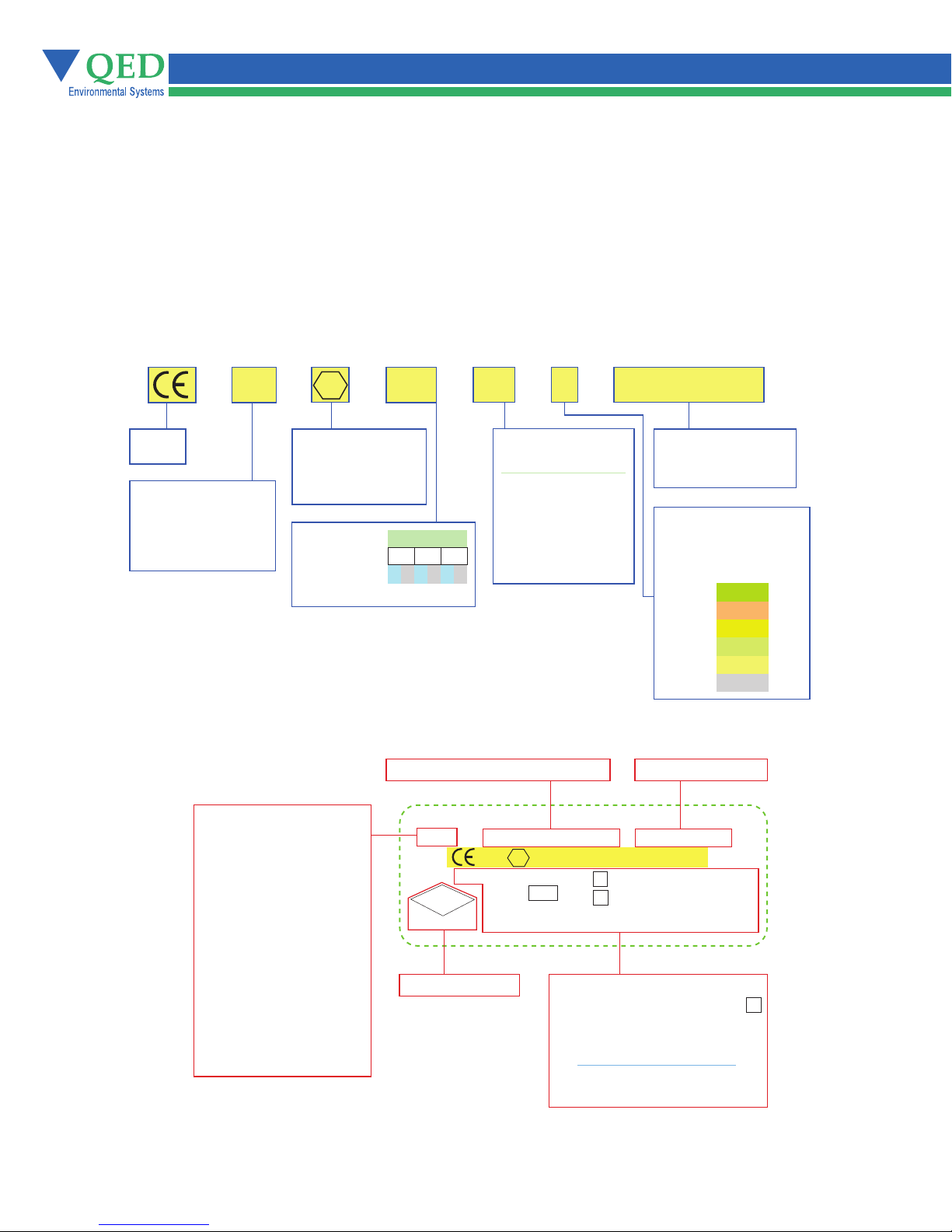
Chapter 2 ATEX Certifications, Label Detail and Explanation
Equipment with an ATEX label similar to the example in Figure 1, is ATEX certified.
Equipment without the label is not ATEX certified.
Figure 1 explains the ATEX label, Figure 2, (following Page) shows the label location and
appearance.
Figure 1
This equipment has been certified to Hazardous Area Classification:
1725
CE
Symbol
Code No. of Notified
Body Certifying
Quality Management
System
of Manufacturer
Equipment Model:
= 2-inch AutoPump
AP2
= 3-inch AutoPump
AP3
= 4-inch AutoPump
AP4
= 4-inch AutoPump
AP4+
= Genie Pump
GNE
= Bladder Pump
BP
= 2-inch Specific
SPG2
Gravity Skimmer
= 4-inch Specific
SPG4
Gravity Skimmer
= 2-inch Selective
SOS2
Oil Skimmer
= 4-inch Selective
SOS4
Oil Skimmer
X
3
Indicates That
the Equipment
May Be Used in
a Hazardous Area
Group
Catagory
Atmosphere*
*G=Gas D=Dust
II
1
G D G D G D
Manufacturer, Zip Code, Country
1
G
II
2
TL EX DIS IN
AP4+
FM
APPROVED
Approving Entity
II
c
B
Protection Method
is by Construction
The Equipment
May be Located
Where Flammable
Gases and Vapors
3
MAXIMUM PRESSURE
of Group IIB May
QED, 94577-2640, USA
1725
YEAR
PAT. 5004405,
5641272, 5495890, 5358038
6T
be Present
X
3
II
c 1 65
1
G
Maximum Operating Pressure
as Appropriate and as Noted
T
a
Certificate Number
FM08ATEX0028
B
II
*Serial Number May be
LocatedOutside the Label
II
T
T
a
6
9.0 BAR (130 PSI)
13.8 BAR (200 PSI)
Year of Manufacture
Patent Number(s)
Serial Number*
o
II
c c
1 6
Allowable Ambient
Temperature Range
for Equipment
Minimum Auto
Ignition Temperature
of Surrounding
Substance by Class
o
o
C C
t
o
S/N:AP4+C-XXXXX
t
T1
T2
T3
T4
T5
T6
o
o
5
450° C
300° C
200° C
135° C
100° C
85° C
X
3
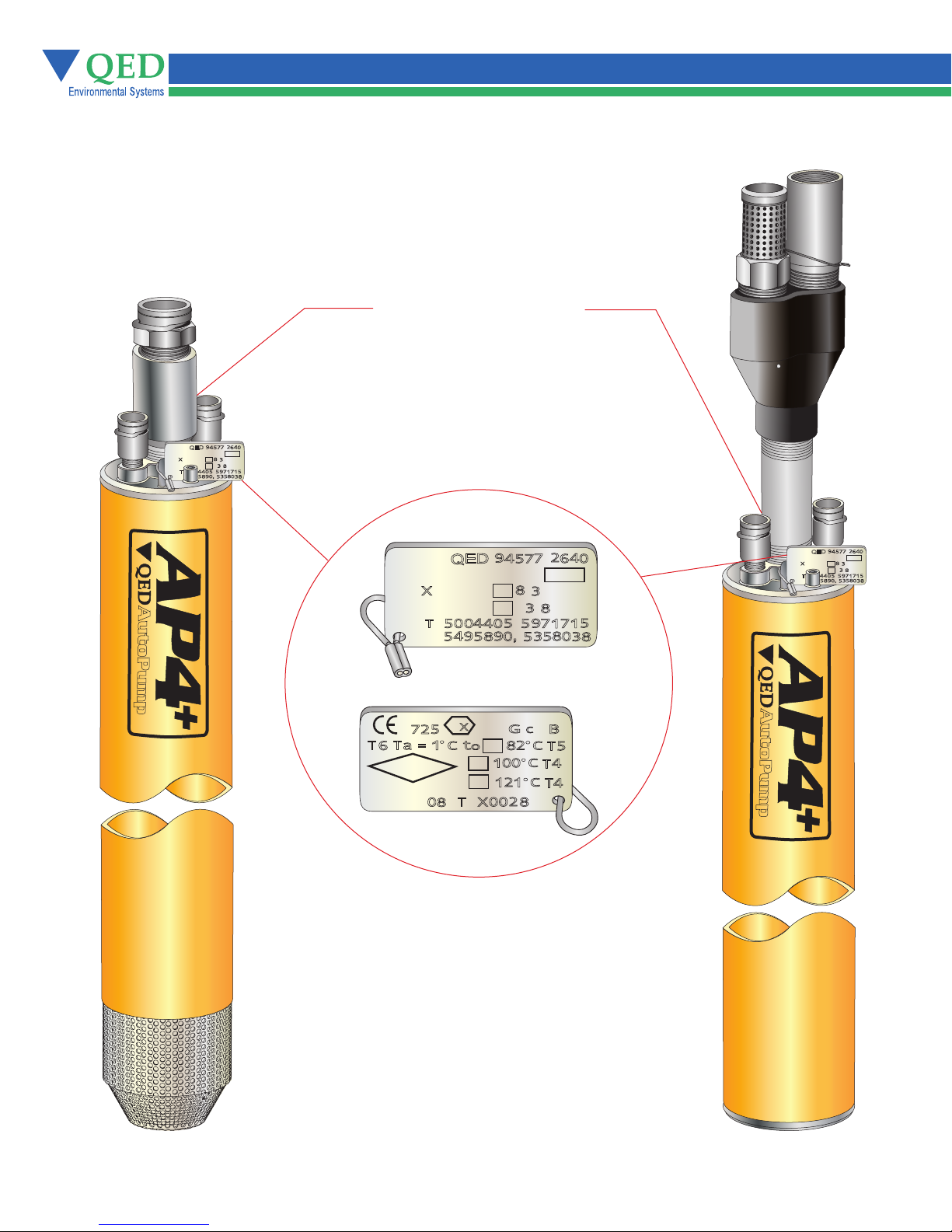
Figure 2 ATEX Label Location and Appearance
Figure 2
Bottom Loading
A
M
P
P
AutoPump
Top Loading
Pump Serial Numbers
Located on the Pump’s Head
I
2
,
9
4
7
,
O
6
4
577
ED
Q
4
P
+
E
A
R
Y
A
U
A
X
E
R
T
A
A
8
B
.
MMU
I
SSS
.
R
3
A
R
U
3
E
8
1
.
B
R
,
,
5
4
9
5
7
OOO
4
5
1
1
,
4
8
9 9
3
5555
O O
8
3
5
8
Obverse View
I
2
,
9
4
7
,
O
6
4
577
ED
Q
4
P
A
+
E
A
R
Y
A
I
2
9
7
,
4
R
E
4
4
55
8
577
E
A
R
Y
8
.
3
3
1
,
9
5
OOO
5
,
3
O O
5
8
.
7
ED
Q
4
P
A
+
A
U
A
M
MMU
X
I
P
E
SSS
R
P
U
.
T
5
A
4
9 9
,
4
O
6
A
B
R
A
B
R
,
5
1
1
8
5
3
8
U
A
M
X
I
P
E
SSS
R
.
T
A
P
A
8
B
.
MMU
R
3
A
R
U
3
E
8
1
.
B
R
,
,
5
4
9
5
7
OOO
4
5
1
1
,
4
8
9 9
O O
3
5555
8
3
5
8
Reverse View
X
1
a
T
T
6
F
APPROVED
7
M
MF
3
5
2
t
C
O
1
=
E
O
T
8
A
AutoPump
C
G
1
I
I
OO
1
1 1
O
X
O
B
II
C
2
8
2
2
5
T
C
4
T
C
4
T
8
4

Chapter 3: Overview
The AutoPump® fills and empties automatically, and is very easy to install, use, and maintain.
The AutoPump is a pneumatic fluid extraction pump that pumps in pulses. It handles any liquid which flows freely
into the pump and is compatible with the component materials and with the connecting hoses. The AP4+ is intended
for vertical operation in well casings with a 3.75-inch or greater internal diameter. It can pump particles up to
1/8-inch in diameter.
The AutoPump is very versatile and available in a wide range of lengths, valve arrangements, and materials of
construction to meet particular site specifications.
Equipment will vary by application and site specifications. (See Chapter 3)
General Specifications
Pump Diameter:
Pressure Range:
High Pressure Option:
Flow Ranges:
3.6 inch (91 mm)
5 - 120 psi (0.4 - 8.5 Kg/cm²)
5 - 200 psi (0.4 - 14.1 Kg/cm²)
0-14 gallons per minute (0-53 liters per minute)
This is How it Works
The AutoPump is a submersible compressed air-driven pump which fills and empties automatically. It also controls
the fluid level in a well automatically. The pump fills (See Figure 1) when fluids enter either the top or bottom check
valve. Air in the pump chamber exits through the exhaust valve as the fluid fills the pump. The float inside the pump
is carried upwards by the fluids rising in the casing until it pushes against a stop on the control rod, forcing the valve
mechanism to switch to the discharge mode.
The switching of the valve causes the exhaust valve to close and the air inlet valve to open. This causes the pump
to empty (see Figure 1) by allowing compressed air to enter the pump. This pressure on the fluid closes the inlet
check valve and forces the fluids up the discharge line and out of the pump through the outlet check valve. As the
fluid level falls in the pump, the float moves downward until it pushes against the lower stop on the control rod, forcing
the valve mechanism to switch to the fill mode. The outlet check valve closes and prevents discharged fluids from
re-entering the pump. The filling and discharging of the pump continues automatically.
NOTE: The figures shown here are simplified schematics.
5
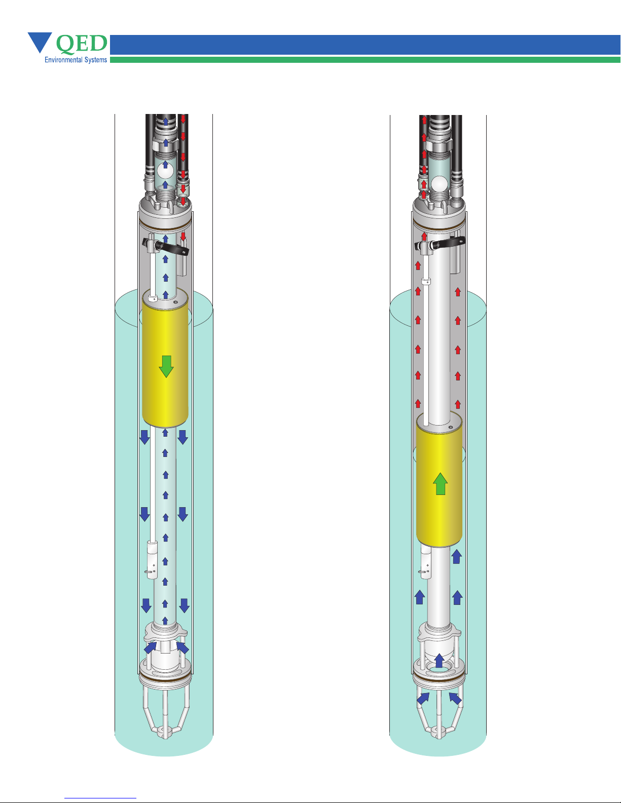
Figure 3 - How it Works
Pump FillingPump Emptying
Pivoting Lever
Tipped Upward
By Rising Float
Compressed Air
Flowing Into
Pump
As Pump Empties,
Float Descends
Air Exhausting
From Pump
Upper
Float Stop
Pivoting Lever
Tipped Downward
By Descending
Float
Lower
Float Stop
Check Valve Seated
Sealing Inlet
As Pump Fills,
Float Rises
Lower
Float Stop
Check Valve
Unseated
Allowing
Liquid into
Pump
6
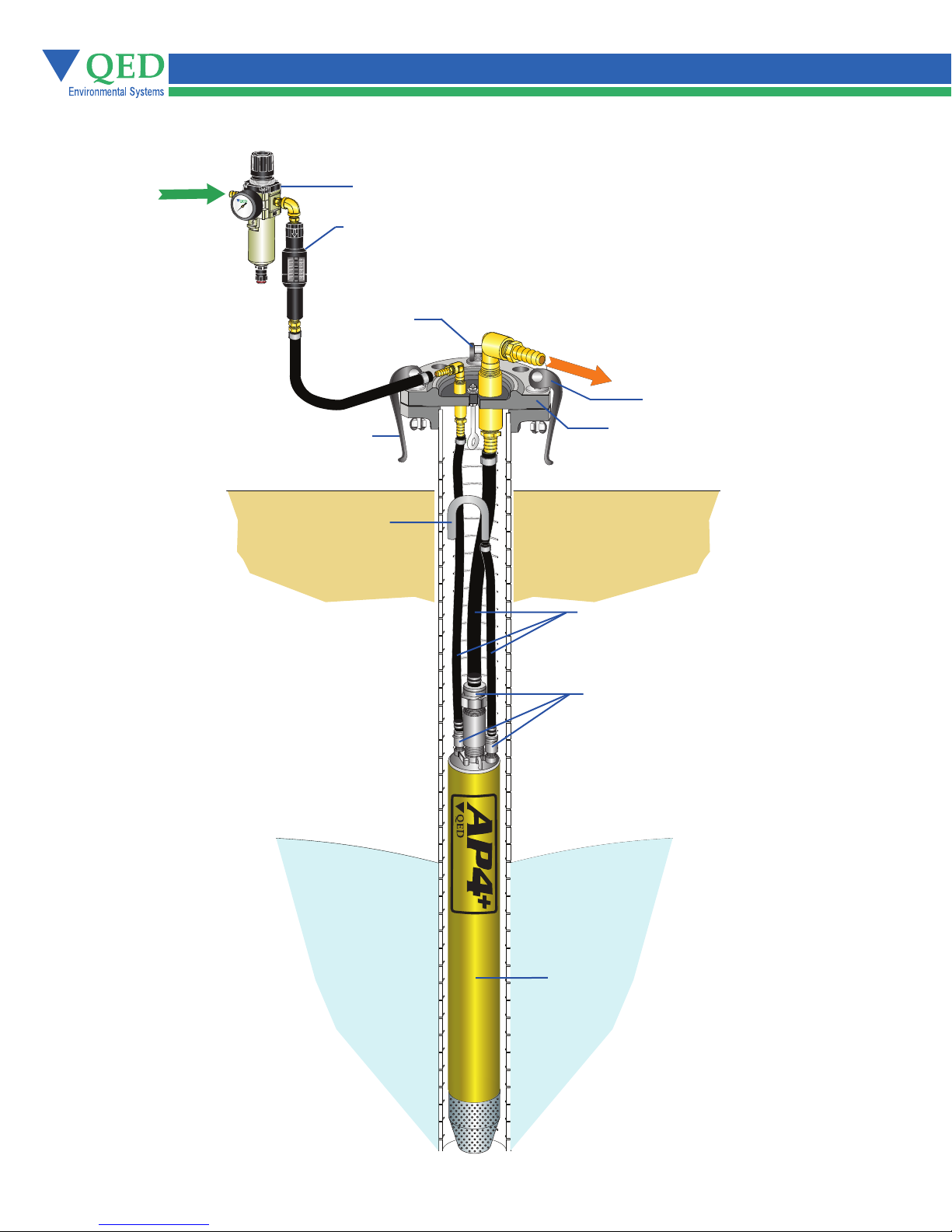
Figure 4 - Overview of the AP4+ System
AP4+ System provides everything required for pumping fluid from a well.
Air
Supply
From
Compressor
8
0
0
6
1
0
0
4
0
1
2
0
2
0
www.qedenv.com
1
4
0
0
1
6
0
Filter/Regulator
Cycle Counter
999999
111111
000000
Easy Bolt
Fluid
Discharge
Easy Bolt
Easy Bolt
Note: Support Harness, Rope, and
Tubing Sheath Omitted for Clarity
Wellhead
Air Exhaust
Tubing
Easy Fittings
pmuPotuA
Pump
7
Chapter 4: Equipment
Unpacking
During the unpacking procedure, check for the following:
• All parts on the packing list have been included in the box
• All fitting openings are unobstructed
• The equipment has not been damaged in shipment
Equipment List
The equipment list will vary depending on site specifications, but the following list is a typical configuration
1. Top-Loading or Bottom-Loading AP-4 with support harness
2. Single stage filter/regulator with:
•
5 Micron filter with auto drain tap
•
Pressure regulator with gauge
•
Maximum operating pressure 120 P.S.I. (8.4 Kg/cm²)
3. Pump Cycle Counter (PCC)
4. Pump support system:
• pac lleW
• epor eriw SS ro ylbmessa knil-kciuq htiw epor troppus enelyporpyloP
(Alternate materials as required)
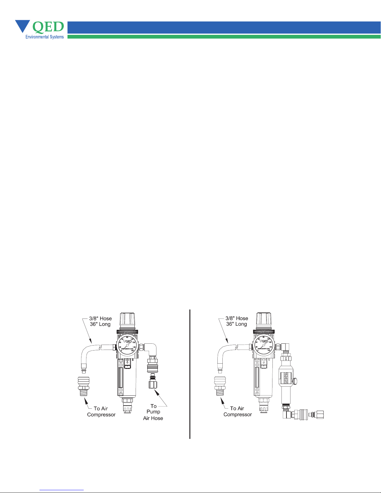
Single Stage Filter/Regulator
A single stage 5 Micron particulate air filter/regulator has a manual or an optional automatic drain and is installed
on the system air supply line. The filter/regulator removes particles and water droplets from the
air passing to the AP4+.
NOTE: Too much air pressure can result in low pump efficiency
Figure 5 - Single Stage Filter/Regulator with Quick-Connects
Part # 302468
For Standard Systems
Maximum operating pressure 120 P.S.I. (8.4 Kg/cm²)
Part # 302470
For Systems with Pump Cycle Counter
8

Chapter 5: Installation
1. Cover the pump tubing/hose ends with tape if they are to be pulled through trenches or laid on the
ground. This is to prevent debris from entering the lines.
2. Blow out all water and particles from compressed air conduits (including downwell pump air supply lines)
and fluid lines for at least 10 seconds after the water and particles exit before connecting them to the
system.
3. Slip clamps over appropriate tubing/hose prior to connecting the tubing/hose to the pump barbs.
4. Push tubing/hose down flush with the fitting's nut if possible; cover at least three barbs if three or more
are present (Note: when installing tubing in freezing weather, tubing can be dipped in warm water for a
few seconds to soften the nylon).
5. Attach pump support rope/cable to the pump.
6. Attach pump air supply and liquid discharge lines to the well cap. Attach the air exhaust line to the well
cap if the pump air is to exhaust outside the well (Note: the liquid discharge line is always the largest
diameter of the three lines, and the air supply line is always the smallest diameter).
7. Connect the pump air supply and liquid discharge lines to the appropriate surface lines/headers.
8. Turn on the air pressure to the pump (minimum of 0.5 psi per foot of vertical static head).
Caution: Submerging the pump before supplying it with air will result in fluid entering the exhaust tubing/hose.
Those fluids will be discharged from the exhaust tubing/hose during the first few cycles of the pump. If this
discharge will not be confined to the well; i.e., if the air exhaust line is routed outside the well*, it is important
to make sure that the air exhaust line is not directed such that equipment/ personnel could be splashed by the
discharged fluid when air is turned on to the pump.
Note: Submerging the pump before supplying it with air can also result in fluid entering the air supply line.This
fluid from the well can contain particles, which could interfere with operation of the pump's air valve.
9. Lower the pump to the desired depth in the well.
10. Secure the pump by tying off the pump support line or by placing the well cap (or flange) on the well.
11. Increase the air pressure to the pump until the pump is pushing the fluid out at the desired rate. With
sufficient air pressure (at least 10 to 15 psi higher than the vertical static head), the pump will gradually
draw down the fluid level in the well to the level of the pump. The time required for this draw down varies
with the yield of the well as compared to the flow rate of the pump. The maximum recommended pump
operating pressure is 120 psi.
Note: If the well environment is such that deposition occurs on stainless steel parts, the operator
may wish to raise the pump above the water level during a shutdown of the system.
* Routing the air exhaust in vacuum wells:
QED controllerless pumps automatically control the liquid level in the well. Under normal conditions,
the liquid level will be maintained at a point approximately one foot below the top of a bottom load
pump (this is the pump's actuation point). The pump will automatically start and stop as needed to
maintain the level at this actuation point.
When QED controllerless pumps are used in wells that are under vacuum, and the exhaust air is
routed into the well, the well level will be maintained at this normal actuation point. If, however, the
well is under vacuum and the exhaust air is routed outside of the well (to atmospheric pressure),
the actuation point of the pump will be higher than the normal actuation point by a distance equal
to the amount of vacuum applied to the well (expressed in "inches of water column"). Please note
that the pump will still function normally and maintain the liquid level, albeit a higher level.
9

Chapter 5: Installation
Hose Bundles
Hose bundling or the use of jacketed tubing reduces equipment entanglement at the well surface, and
aids the removal of the pump from the well. Bundling also assists in positioning the pump and
down-well hose assembly against one side of the well casing. Maximum space is created for other
items, such as probes, to be periodically placed inside the well.
Follow these instructions to create a hose bundle:
1. Lay the equipment on the ground and make all of the necessary hose connections. (See Figure 5).
2. If a well cap is supplied, install it on the hoses. (See Figure 4).
3. Connect the quick-link assembly on the support rope to the eyebolt on the AP4+ and lay the
support rope out along with the hoses. Make sure that none of the hoses or support ropes are
crossing over each other (See Figure 5).
Note: To make the next step easier, pull the support rope and the hoses taut.
4. Starting at the AutoPump end of the hose, put a tie-wrap through the center of the braided support
rope just above the uppermost quick-connect or barb on the AutoPump (See Figure 5).
5. Pulling the rope taut, put the tie-wrap around the fluid discharge hose with the rough surface
outwards. Cross the ends and complete the connect the tie-wrap make sure it is straight and is not
kinking the hoses (See Figure 5).
Note: After completing this step, the fluid discharge hose will be attached to the support rope and
the exhaust hose. At this point the air supply hose is still lying free.
6. Place the next tie-wrap two feet towards the well cap from the first. Secure the air supply hose
rather than the exhaust hose.
Note: It is important to put the tie-wraps approximately two feet apart to keep a proper discharge
hose/support rope bundle. Experience has shown that spreading the tie-wraps further apart than
two feet increases the probability for hose kinking.
7. Continue to alternate the air exhaust and the air supply tie-wraps every two feet, stopping about
five feet from the wellhead.
8. Being careful not to leave any sharp edges, cut the excess from the tie-wraps.
You now have a down-well bundled hose assembly that supports both the hoses and the down-well
equipment.
10
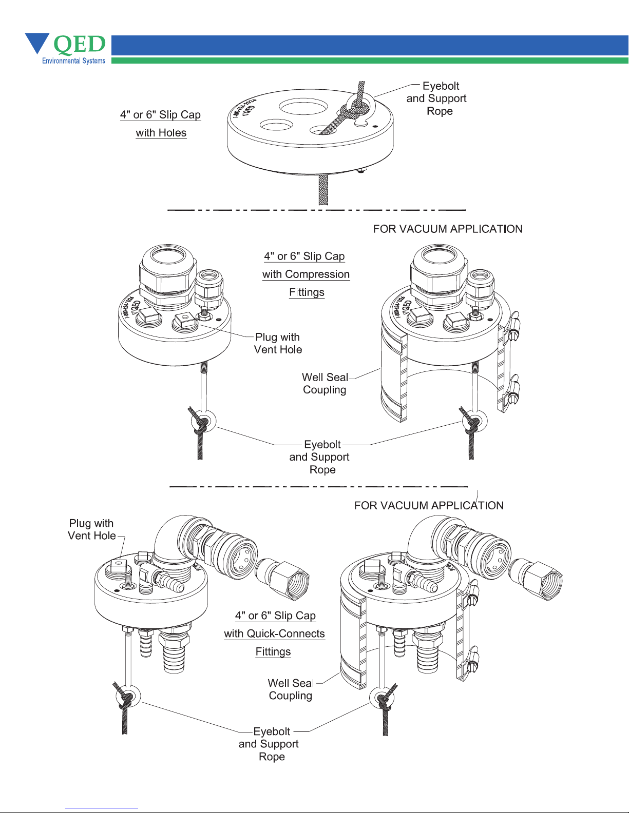
Figure 6 - Examples of Well Caps
11
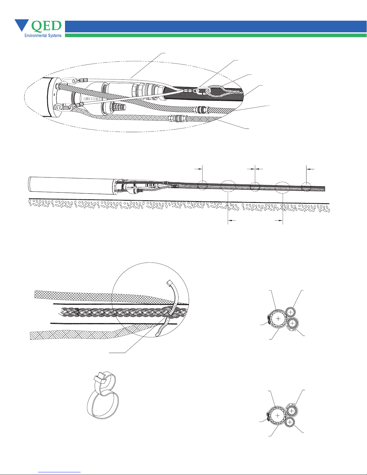
Figure 7 - Hose Bundling
Air Exhaust Tie-Wraps in Between Air Exhaust Tie-Wraps Every 4 Ft. (122 Cm)
Support Harness
Quick Link Assembly
Support Rope
Fluid Discharge
Hose (Black)
Air Exhaust
Hose (Blue)
AutoPump® Air
Hose (Green)
Tie-Wrap Detail
Thread Tie-Wraps
Through Support Line
Air Exhaust Tie-Wraps in Between Air Hose Tie-Wraps Every 4 Ft. (122 Cm)
Air Exhaust Tie-Wrap
Fluid Discharge
Hose (Black)
Support Rope
Air Exhaust
Tie-Wrap
Air Hose Tie-Wrap
Fluid Discharge
Hose (Black)
AutoPump Air
Hose (Green)
Air Exhaust
Hose (Blue)
AutoPump Air
Hose (Green)
Figure 8 Tie-Wrap Layout
12
Support Rope
Air Hose
Tie-Wrap
Air Exhaust
Hose (Blue)

Chapter 6: Maintenance
Removing the Pump’s Casing
1. Remove the bolt at the bottom of the pump which holds the inlet screen in place (bottom loading pumps only).
2. Remove the three bolts at the bottom of the pump which hold the inlet in place. (See Figures 6,7,8,and 9)
3. Remove. the inlet from the pump’s casing by pulling it out.
4. Twist and slide the casing down off the pump’s frame.
Cleaning Pump Interior
The inner workings of the pump should now be exposed for inspection and cleaning. (See Figures 6 Through 11)
Note: A Scotch Brite® abrasive pad is useful for cleaning debris from the pump components.
.1 Gently brush off built-up solids from the float, the discharge line, the pump casing and the control rod guide.
2. The pump can be steam cleaned without damage.
3. Remove thick deposits of hardened scale on the discharge tube by using a handbrush or by lightly tapping the
discharge tube with a small hammer. Be careful not to strike any pins or other components, since they may be
damaged.
Iron Build-up Cleaning Procedure
After the casing has been removed from the AutoPump please follow the procedure below:
1. The bottom “spider” should be removed by unthreading it from the pump’s discharge pipe. (See Figures 6,7,8,and 9)
2. Visually inspect the 1 inch stainless steel fluid discharge pipe for scale build-up or debris. Also, do the same with the float
that rides up and down on the SS discharge pipe.
3. Should there be scale deposits on either or both the discharge pipe or float, then remove the float from the SS fluid discharge
pipe as follows . (See Figures 6,7,8,and 9)
Remove the small SS hairpin from the bottom spring cup. Removing the hairpin and spring cup will allow you to
remove the spring, sliding stop and float from the SS discharge pipe.
4. The 1 inch stainless steel fluid discharge pipe can now be cleaned using either a ScotchBrite pad, a wire brush or
a wire wheel on either a drill or a grinding machine. After removing the scale/debris, it is recommended the pipe
be water rinsed.
Both the internal and external surfaces of the float will generally require cleaning. The cleaning material choices
include a Scotch Brite pad, and a light grade 150 sandpaper.
The plates are removed to ease cleaning, they should be replaced on the same float end from which they came.
That is, the plates should maintain their original top and bottom positions.
5. The white plastic square Control Rod is the next component to be cleaned. The control rod is the item that fits
through the smaller hole in the float and is adjacent to the SS discharge pipe in the assembled pump. To Clean
use the Scotch Brite pad or a razor or Exacto knife (not sandpaper).
6. The final component to be cleaned is the outer AP4+ casing. The fastest and most effective way to clean out
the inside surface of the pump casing is to use a three-stone honing tool. The technique is to move the hone in and-out, a half dozen times or so through, each end of the casing. The time for the casing cleaning should take no
longer than 5 minutes.
The AutoPump is now ready for re-assembly by following the steps above in reverse order.
Note: Before threading the bottom “spider” onto the pump’s discharge pipe, be sure to wrap the discharge pipe’s
threads completely with Teflon tape.
13
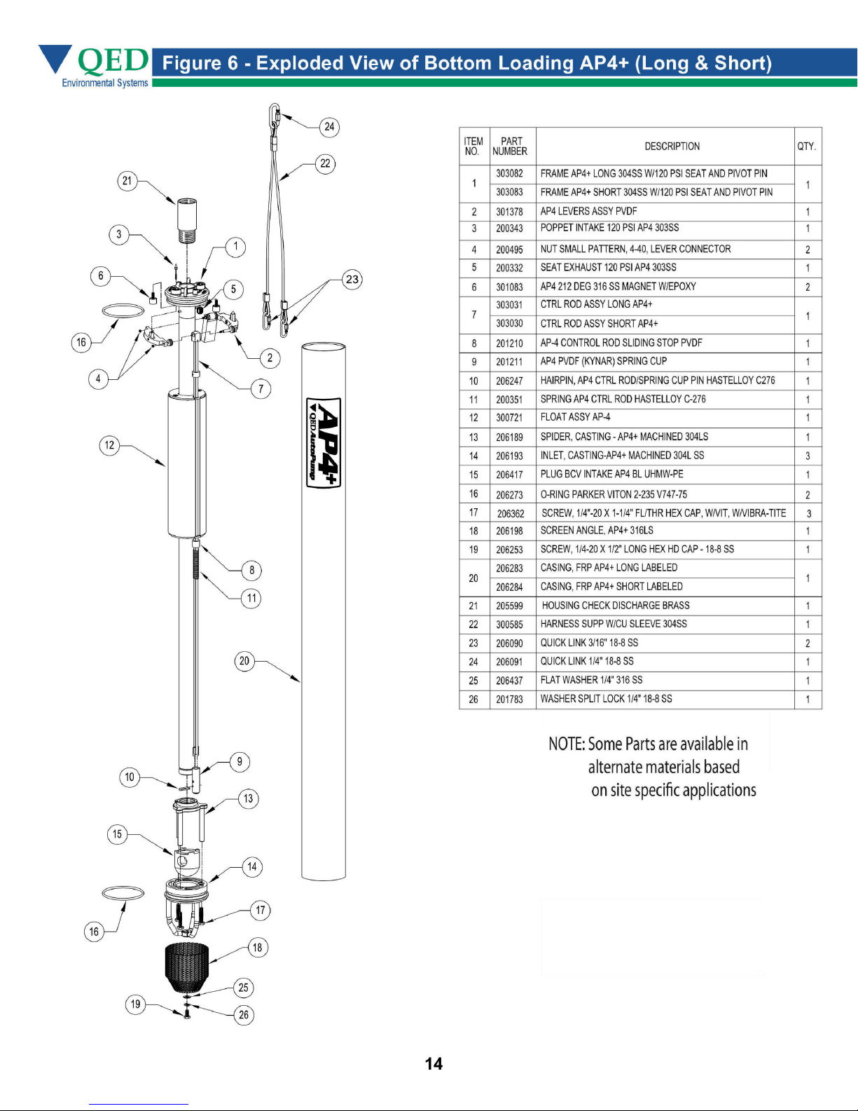


Figure 10 - Exploded View of Top Loading AP4+ (Long & Short)
NOTE: Some Parts are available in
alternate materials based
16

Figure 11 - Exploded View of Top Loading AP4+ Low Drawdown
NOTE: Some Parts are available in
alternate materials based
17

Figure 12 - Exploded View of AP4+ Lever Assembly
Parts Assembled
18
ITEM NO. PART NUMBER DESCRIPTION
200359
1
200359
1
200665
1
200337
2
200337
2
200336
2
201465
3
200497
4
301654
5
200328
6
200495
7
200330
8
201053
9
200327
10
200327
10
206008
10
200496
11
201052
12
201458
13
120 P.SI INTAKE POPPET CONNECTOR-LONG
120 P.SI INTAKE POPPET CONNECTOR-SHORT
120 P.SI INTAKE POPPET CONNECTOR-LDD
303 SS 120 P.SI EXHAUST POPPET-LONG
303 SS 120 P.SI EXHAUST POPPET-SHORT
303 SS 120 P.SI EXHAUST POPPET-LDD
316 SS POPPET PIN
PH 15-17 MO POPPET PIN RETAINING E-CLIP
PVDF LEVER /BUSHING ASSEMBLY
303 SS LEVER CONNECTING PIN
4-40 SS SMALL PATTERN NUT LEVER CONNECTING
17-7 COUNTERWEIGHT ROLLER
316 SS COUNTERWEIGHT BUSHING
303 SS COUNTERWEIGHT-LONG
303 SS COUNTERWEIGHT-SHORT
303 SS COUNTERWEIGHT-LDD
VITON BUMPER O-RING
316 SS CONTROL ROD ADAPTER BUSHING
PVDF CONTROL ROD ROLLER
QTY.
1
1
1
1
1
1
2
2
2
1
2
4
1
1
1
1
4
1
2

Figure 13 - Exploded View of 1 Inch Check Valve
Adapter
OR
Barbed
Fitting
Check
Ball
Check
Valve
Housing
19

Chapter 7: Troubleshooting & Repairs
Problems may occur and usually can be easily resolved by following these instructions. If, after careful reading and
service, you cannot resolve the problem, please contact the QED Environmental Systems (QED) Service Department
at (800) 537-1767.
Caution: Wear goggles, gloves, and coveralls when servicing this system.After troubleshooting is completed and
before assembling the pump, slowly move the float through its range to ensure that the lever will trip even if the
pump fills and empties slowly.
Note: Maintenance for disassembly and cleaning instructions.
Possible Causes
Detailed Instructions
Follow This Chart
Air Supply
Fluid Level
Air Exhaust Restricted
Fluid Inlet Clogged
5. Debris, Scale or Very
Viscous Fluid
6. Lever Pivot Wear X
7. Debris in Air Inlet
Valve
8. Fluid Check Valve
9. Valve Timing
Pump Not Cycling
X1. X
X2.
X3. X
X4.
X
X
X
X
Symptoms
Pump Not Cycling,
Volume is Reduced or
There is No Discharge
X
X
Air in Fluid or
Discharge
X
Troubleshooting
1. Air Supply
If the air pressure is too low, or if the flow is severely restricted, the pump will not cycle. The minimum air
•
pressure requirement for pump operation is 0.5 psi per foot of vertical static head.
•
If the air pressure exceeds the design limitations of the pump, the pump may fail to cycle, or the exhaust
may have locked up and caused air to enter the fluid discharge.
2. Fluid Level
The fluid level must be above the fluid inlet on a Top-Loading pump. On a Bottom-Loading pump, the fluid must
•
be no lower than 9 inches below the head of the pump
:detcirtseR tsuahxE riA.3
• .retemaid ni llams oot ro ,deggulp ,deknik eb ton tsum enil tsuahxe ehT
The air exhaust outlet must be above the fluid level
•
• .enil yrevocer ropav gninoitcnuf a ro erehpsomta eht ot detnev eb tsum llew eht ,llew eht ni stsuahxe ria eht fI
20

Chapter 7: Troubleshooting & Repairs
• If the air exhausts to the atmosphere (outside the well) and a vacuum is drawn on the well, the pump may fail
to fill. In order for the pump to fill under these conditions, the pump must be submerged to make up for the
pressure difference between the atmosphere and the partial vacuum in the well.
The pressure difference, expressed as feet of water column (FT. W. C.), is the distance the fluid must be above
the pump before it can fill.
4. Fluid Inlet Clogged
•
If the fluid inlet screen is clogged with debris water cannot enter the pump.
5.Debris, Scale, or very Viscous Fluid
If debris, scale or a very viscous fluid has accumulated inside the pump, the float may not move freely up and
•
down, or the control rod may not slide easily through the float.
Clean the float, control rod, and the casing. (See Chapter 5 for cleaning instructions).
•
6. Lever Pivot Wear
• Grasp the center of the lever with thumb and forefinger. Rotate the lever to horizontal.
• Push up and down, toward and away from the head. Confirm that there is less than 1/32 inch of movement.
•
Replace the levers if the pivot hole is worn
7. Debris in Air Inlet Valve (First check #6-Lever Pivot Wear)
•
Open the pump. Connect the air supply. Pull the control rod down. Listen to determine if air leaks through. If
air still leaks through the valve with the control rod down, the air tubing must be removed to access the valve
inlet to check for debris in the valve. Clean the valve by blowing air or water through it from both ends.
Push the rod upwards. If little or no air passes through, remove the tubing to access the valve inlet. Blow air
•
through the valve from the poppet side to clear debris from the ball and seat.
8. Fluid Check Valves
• Open the pump. Hold the pump vertically and pour water into the discharge check valve. If water flows through,
clean the valve.
•
Remove the valve and use emery cloth or a very fine sand paper to polish the surface where the ball seats.
• If the pump is a Bottom-Loading design, inspect the seat of the bottom check valve for debris and wear. Clean
or replace if necessary.
If the pump is a Top-Loading design, remove the fluid inlet check valve and inspect the seating surface and the
•
ball for debris and wear.
9. Air Inlet Valve Timing
•
(First check lever pivot wear per #6 above)
• Call the QED Service Department for correct air valve timing for your pump.
21

Chapter 7: Troubleshooting & Repairs
Returning Equipment for Service
If the equipment needs to be returned to QED for servicing, please follow these steps:
1. Call the QED Service Department and obtain a Return Material Authorization (RMA) number. Please have
available the contact person’s name, company name and address, phone number, fax number, reason for the
return, and the names of the chemicals to which the equipment has been exposed.
2. Clean all equipment before shipping. (See Equipment Cleaning Requirements at the end of this section). If the
equipment must be cleaned after it arrives at QED, the customer will be charged for the cleaning and disposal of
material, if necessary. (Cost can be $500.00 per piece of equipment cleaned.) It is also important to note that
shipping equipment with a known hazardous waste is a violation of federal law. Drain and dry all equipment after
cleaning.
3. Package the equipment so that it will not be damaged in shipment. Use bubble pack rather than styrofoam flakes
as packing material.
4. Ship the equipment via a carrier and service level (i.e., one-day, two-day shipping) in consideration of probable
service time and return shipment time.
5. It is recommended that such shipments be insured so, if the shipment is badly damaged or lost, the customer can
replace the equipment at little or no cost.
6. Include the contact’s name, company, phone number and RMA number given by QED.
7. Write the RMA number on the outside of the packaging so it will be directed immediately to the QED Service
Department.
Equipment Cleaning Requirements
If the equipment is to be shipped to another site or to the factory for service, it needs to be thoroughly cleaned before
leaving the site. Cleaning the equipment protects the user (sender), the shipper, and the receiver from dirt and/or
contaminants. If the equipment is not cleaned prior to shipping for servicing, it may be severely delayed, refused or
the shipper may be charged a cleaning fee. Before packing and shipping, ensure that the equipment is dry inside and
out.
To Clean the AP4+:
1. Pump clean water or water with a gentle soap solution (e.g. Dove Dish Soap) through the pump to remove free
product and particles.
2. Rinse all soap off of the equipment.
3. Soak and rinse the outside of the unit with water to remove loose debris and dirt.
4. Steam clean inside and out to remove difficult dirt and contaminants.
Caution: Use low pressure (less than 40 psi) when steam cleaning.
22

Specifications - Bottom Inlet, Long
AP4
Max. Flow
Length
Advantages
1. The original automatic air-
powered well pump, proven
worldwide over 23 years
2. The highest ow rates and
deepest pumping capabilities in
the industry
+
14 gpm (53 lpm)
O.D.
51.4 in. (131cm)
B
Description
The AP4+ Bottom Inlet Long AutoPump provides maximum
)mm 19( ni 6.3
4PA
+
pmuPotuA
capabilities and ow in a bottom inlet pump for 4” (100 mm)
diameter and larger wells with shorter water columns and/or
the need to pump down to lower water levels, compared to
full-length pumps. It is oered in optional versions to handle
even the most severe remediation and landll pumping
applications, and delivers ow rates up to 14 gpm (49 lpm)*.
The AP4+ Long Bottom Inlet AutoPump is complemented by
the most comprehensive selection of accessories to provide
a complete system to meet site specic requirements. Call
QED for prompt, no-obligation assistance on your pumping
project needs.
The AutoPump Heritage
The AP4+ Bottom Inlet Long AutoPump is part of the
famous AutoPump family of original automatic air-powered
pumps, developed in the mid 1980s specically to handle
unique pumping needs at remediation and landll sites.
Over the years they’ve proven their durability at thousands
of sites worldwide. AutoPumps are designed to handle
dicult pumping challenges that other pumps can’t, such
as hydrocarbons, solvents, suspended solids, corrosives,
temperature extremes, viscous uids and frequent start/stop
cycles. Beyond just the pump, AutoPump systems oer the
most complete range of tubing, hose, connectors, wellhead
caps and accessories to help your installation go smoothly.
This superior pumping heritage, application experience and
support back up every AutoPump you put to work on your
project.
3. Patented, proven design for
superior reliability and
durability, even in severe
applications
4. Handles solids, solvents,
hydrocarbons corrosive
conditions, viscous uids and
high temperatures beyond the
limits of electric pumps
5. Five-year warranty
23

Specifications - Bottom Inlet, Long
AP4
+
B
AP4
AutoPum
+
p
Liquid Discharge
Air Supply
Exhaust
Specifications & Operating RequirementsPump Dimensions
Model
Liquid Inlet Location
Overall Length With Extended Screen
Weight
Maximum Flow Rate
Pump Volume/Cycle
Minimum Accuation Level
Standard Pump
Maximum Depth
Air Pressure
Air Usage
High Pressure Pump
Maximum Depth
Air Pressure
Minimum Liquid Density
Standard Construction Materials¹
Pump Body
Pump Ends
Internal Components
Tube & Hose Fittings
Fitting Type
4" - Long AP4+ Bottom Inlet
Bottom
O.D.
3.6 in. (91 mm)
51.4 in. (131 cm)
16.7 lbs. (7.6 kg)
14 gpm (53 lpm)* - See Flow Rate Chart
0.58 - 0.78 gal (2.2 - 3L )
38.4 in. (98 cm)
250 ft. (76 m)
5 - 120 psi (0.4 - 8.4 kg/cm2)
0.4 - 1.1 scf / gal. (3.0 - 8.5 liter of air /
fluid liter) - See air usage chart
425 ft. (130 m)
5 - 200 psi (0.4 - 14.1 kg/cm2)
0.7 SpG (0.7 g/cm3)
Fiberglass or Stainless Steel
Stainless Steel
Stainless Steel, Viton, PVDF
Brass or Stainless Steel
Barbs, Quick Connects or Easy Fittings
³,
Hastelloy-C
Length with Extended Screen Attached 51.4" (131 cm)
Actuation Level 38.4" (98 cm)
Inlet
O.D. 3.6" (91 mm)
Application Limits (Base model)
AP4+ AutoPumps are designed to handle
the application ranges described below.
For applications outside these ranges,
consult QED about AP4+ upgrades.
Maximum Temperature: 180°F (82°C)
pH Range: 4-9
Solvents and Fuels: diesel, gasoline,
JP1-JP6,#2 heating oils, BTEX, MTBE,
landfill liquids
Tube & Hose Options
Tubing Materials²
Sizes - Liquid Discharge
Pump Air Supply
Air Exhaust
Sizes - Liquid Discharge
1
Material upgrades available
2
Applies to QED supplied tubing;
other tubing sources may not
conform to QED fittings.
Hose Material
Pump Air Supply
Air Exhaust
Nylon
1 in. (25 mm) or 1-1/4 in. (32 mm) OD
1/2 in. (13 mm) OD
5/8 in. (16 mm) OD
Nitrile
3/4 in. (19 mm) or 1 in. (25 mm) ID
3/8 in. (9.5 mm) ID
1/2 in. (13 mm) ID
Long and short AP4+ AutoPumps are warranted for
five(5) years: Low-Drawdown AP4+ AutoPumps are
warranted for one (1) year.
*Consult QED for higher flow requirements
24

Specifications - Bottom Inlet, Long
AP4
+
B
3/4 inch (19 mm)
Inside Diameter Discharge Hose
(Equivalent to 1-Inch O.D. Tubing)
6-INCH (15 cm) SUBMERGENCE OF PUMP HEAD
18
16
GALLONS
PER
MINUTE
WITH
3/4-INCH
I.D. HOSE
GALLONS
PER
MINUTE
WITH
3/4-INCH
I.D. HOSE
GALLONS
PER
MINUTE
WITH
3/4-INCH
I.D. HOSE
14
12
AIR INLET PRESSURES
10
8
6
4
40 PSI
2
0
0
2 FT. (60 cm) SUBMERGENCE OF PUMP HEAD
6.1
20
3 Kg/cm
40
12.26018.3
2
80
24.4
18
16
14
12
AIR INLET PRESSURES
10
8
6
4
40 PSI
2
0
0
10 FT. (300 cm) SUBMERGENCE OF PUMP HEAD
20
6.1
3 Kg/cm
40
12.2
2
60
18.3
80
24.4
18
16
14
12
AIR INLET PRESSURES
10
8
6
4
2
0
40 PSI
2
3 Kg/cm
80
40
60
20
0
12.2
18.3
6.1
24.4
100
30.5
100
30.5
100
30.5
120
36.6
120
36.6
120
36.6
140
42.7
140
42.7
140
42.7
100 PSI
7 Kg/cm
70 PSI
5 Kg/cm
160
48.8
100 PSI
7 Kg/cm
70 PSI
5 Kg/cm
160
48.8
100 PSI
7 Kg/cm
70 PSI
5 Kg/cm
160
48.8
180
54.9
180
54.9
180
54.9
Flow Rates
1
1 inch (25.4 mm)
Inside Diameter Discharge Hose
(Equivalent to 1.25-Inch O.D. Tubing)
68.1
60.6
53
APPROXIMATE
LITERS
45.4
37.9
30.3
22.7
2
15.1
PER
MINUTE
WITH
19 mm
I.D. HOSE
7.6
2
200
0
FT.
Meters
61
DEPTH
IN WELL
68.1
60.6
53
APPROXIMATE
LITERS
45.4
37.9
30.3
22.7
2
15.1
PER
MINUTE
WITH
19 mm
I.D. HOSE
7.6
2
200
0
FT.
Meters
61
DEPTH
IN WELL
68.1
60.6
53
APPROXIMATE
LITERS
45.4
37.9
30.3
22.7
2
15.1
PER
MINUTE
WITH
19 mm
I.D. HOSE
7.6
2
200
0
FT.
Meters
61
DEPTH
IN WELL
6-INCH (15 cm) SUBMERGENCE OF PUMP HEAD
18
16
GALLONS
PER
MINUTE
WITH
1-INCH
I.D. HOSE
GALLONS
GALLONS
PER
MINUTE
WITH
1-INCH
I.D. HOSE
GALLONS
PER
MINUTE
WITH
1-INCH
I.D. HOSE
14
12
10
8
6
4
2
0
20
0
6.1
2 FT. (60 cm) SUBMERGENCE OF PUMP HEAD
18
16
14
12
10
8
6
2
0
20
0
6.1
10 FT. (300 cm) SUBMERGENCE OF PUMP HEAD
18
16
14
12
10
8
6
4
2
0
20
0
6.1
AIR INLET PRESSURES
40 PSI
2
3 Kg/cm
40
60
12.2
18.3
AIR INLET PRESSURES
40 PSI
2
3 Kg/cm
40
60
12.2
18.3
40 PSI
2
3 Kg/cm
40
60
12.2
18.3
80
24.4
80
24.4
80
24.4
7 Kg/cm
70 PSI
5 Kg/cm
100
30.5
100
30.5
AIR INLET PRESSURES
100
30.5
120
36.6
120
36.6
120
36.6
140
42.7
140
42.7
140
42.7
160
5 Kg/cm
160
48.8
5 Kg/cm
160
48.8
100 PSI
180
8.84 9.45 16
100 PSI
7 Kg/cm
70 PSI
180
100 PSI
7 Kg/cm
70 PSI
180
54.9
2
2
9.45 16
2
68.1
60.6
53
APPROXIMATE
45.4
LITERS
FT.
Meters
APPROXIMATE
FT.
Meters
APPROXIMATE
FT.
Meters
PER
MINUTE
WITH
25.4 mm
I.D. HOSE
DEPTH
IN WELL
LITERS
PER
MINUTE
WITH
25.4 mm
I.D. HOSE
DEPTH
IN WELL
LITERS
PER
MINUTE
WITH
25.4 mm
I.D. HOSE
DEPTH
IN WELL
37.9
30.3
22.7
2
15.1
7.6
0
200
68.1
60.6
53
45.4
37.9
30.3
22.7
2
15.14
7.6
0
200
68.1
60.6
53
45.4
37.9
30.3
2
22.7
15.1
7.6
0
200
61
1FLOW RATES MAY VARY WITH SITE CONDITIONS. CALL QED FOR TECHNICAL ASSISTANCE.
25

Specifications - Bottom Inlet, Long
AP4 B
uA
t
4PA
Po
mu
+
p
+
STANDARD
CUBIC FEET OF AIR
PER
GALLON PUMPED
(SCF/GAL)
Air Consumption
1.6
1.5
1.4
1.3
1.2
1.1
1.0
.9
.8
.7
.6
.5
.4
.3
40 PSI
3 Kg/cm
100 PSI
2
7 Kg/cm
70 PSI
2
5 Kg/cm
2
12
3/4 inch (19 mm)
11.2
Inside Diameter Discharge Hose
(Equivalent to 1-Inch O.D. Tubing)
10.5
9.7
9.0
8.2
APPROXIMATE
STANDARD
7.5
LITER OF AIR
PER
LITER PUMPED
6.7
(STD L/LITER)
6.0
5.2
4.5
3.7
3.0
2.2
STANDARD
CUBIC FEET OF AIR
PER
GALLON PUMPED
(SCF/GAL)
.2
20 40 60 80 100 120 140 160 180 200
1.6
1.5
1.4
1.3
1.2
1.1
1.0
.9
.8
.7
.6
.5
.4
.3
. .
40 PSI
3 Kg/cm
2
48.87.246.635.034.4218.312.26.1
70 PSI
5 Kg/cm
54.9 61
100 PSI
7 Kg/cm
2
2
1.5
FT.
Meters
12
11.2
10.5
9.7
9.0
8.2
7.5
6.7
6.0
5.2
4.5
3.7
3.0
2.2
DEPTH
IN WELL
1 i
nch (25.4 mm)
Inside Diameter Discharge Hose
(Equivalent to 1.25-Inch O.D. Tubing)
APPROXIMATE
STANDARD
LITER OF AIR
PER
LITER PUMPED
(STD L/LITER)
.2
20 40 60 80 100 120 140 160 180 200
48.87.246.635.034.4218.312.26.1
54.9 61
26
1.5
FT.
Meters
DEPTH
IN WELL

Specifications - Bottom Inlet, Short
AP4 B
Max. Flow
Length
+
13 gpm (49 lpm)
O.D.
39.3 in. (100 cm)
Advantages
1. The original automatic air-
powered well pump, proven
worldwide over 23 years
2. The highest ow rates and
deepest pumping capabilities in
the industry
3. Patented, proven design for
superior reliability and
durability, even in severe
applications
Description
The AP4+ Bottom Inlet Short AutoPump provides maximum
)mm 19( ni 6.3
4PA
+
pmuPotuA
capabilities and ow in a bottom inlet pump for 4” (100 mm)
diameter and larger wells with shorter water columns and/or
the need to pump down to lower water levels, compared to
full-length pumps. It is oered in optional versions to handle
even the most severe remediation and landll pumping
applications, and delivers ow rates up to 13 gpm (49 lpm)*.
The AP4+ Short Bottom Inlet AutoPump is complemented by
the most comprehensive selection of accessories to provide
a complete system to meet site specic requirements. Call
QED for prompt, no-obligation assistance on your pumping
project needs.
The AutoPump Heritage
The AP4+ Bottom Inlet Short AutoPump is part of the
famous AutoPump family of original automatic air-powered
pumps, developed in the mid 1980s specically to handle
unique pumping needs at remediation and landll sites.
Over the years they’ve proven their durability at thousands
of sites worldwide. AutoPumps are designed to handle
dicult pum
as hydrocarbons, solvents, suspended solids, corrosives,
temperature extremes, viscous uids and frequent start/
stop cycles. Beyond just the pump, AutoPump systems
oer the most complete range of tubing, hose, connectors,
wellhead caps and accessories to help your installation go
smoothly. This superior pumping heritage, application
experience and support back up every AutoPump you put
to work on your project.
ping challenges that other pumps can’t, such
4. Handles solids, solvents,
hydrocarbons corrosive
conditions, viscous uids and
high temperatures beyond the
limits of electric pumps
5. Five-year warranty
27

Specifications - Bottom Inlet, Short
AP4 B
+
AP4
A
ut
oPum
+
p
Liquid Discharge
Air Supply
Exhaust
Specifications & Operating RequirementsPump Dimensions
Model
Liquid Inlet Location
Overall Length With Extended Screen
Weight
Maximum Flow Rate
Pump Volume/Cycle
Minimum Accuation Level
Standard Pump
Maximum Depth
Air Pressure
Air Usage
High Pressure Pump
Maximum Depth
Air Pressure
Minimum Liquid Density
Standard Construction Materials¹
Pump Body
Pump Ends
Internal Components
Tube & Hose Fittings
Fitting Type
4" - Short AP4+ Bottom Inlet
Bottom
O.D.
3.6 in. (91 mm)
39.3 in. (100 cm)
13.7 lbs. (6.2 kg)
13 gpm (49 lpm)* - See Flow Rate Chart
0.22 - 0.36 gal (.83 - 1.36 L )
26.7 in. (68 cm)
250 ft. (76 m)
5 - 120 psi (0.4 - 8.4 kg/cm2)
0.4 - 1.1 scf / gal. (3.0 - 8.5 liter of air /
fluid liter) - See air usage chart
425 ft. (130 m)
5 - 200 psi (0.4 - 14.1 kg/cm2)
0.7 SpG (0.7 g/cm3)
Fiberglass or Stainless Steel
Stainless Steel
Stainless Steel, Viton, PVDF
Brass or Stainless Steel
Barbs, Quick Connects or Easy Fittings
³,
Hastelloy-C
Actuation Level 26.7" (68 cm)
Length with Extended Screen Attached 39.3" (100 cm)
Inlet
O.D. 3.6" (91 mm)
Application Limits (Base model)
AP4+ AutoPumps are designed to handle
the application ranges described below.
For applications outside these ranges,
consult QED about AP4+ upgrades.
Maximum Temperature: 180°F (82°C)
pH Range: 4-9
Solvents and Fuels: diesel, gasoline,
JP1-JP6,#2 heating oils, BTEX, MTBE,
landfill liquids
Tube & Hose Options
Tubing Materials²
Sizes - Liquid Discharge
Pump Air Supply
Air Exhaust
Sizes - Liquid Discharge
1
Material upgrades available
2
Applies to QED supplied tubing;
other tubing sources may not
conform to QED fittings.
Hose Material
Pump Air Supply
Air Exhaust
Nylon
1 in. (
25 mm) or 1-1/4 in. (32 mm) OD
1/2 in. (13 mm) OD
5/8 in. (16 mm) OD
Nitrile
3/4 in. (19 mm) or 1 in. (25 mm) ID
3/8 in. (9.5 mm) ID
1/2 in. (13 mm) ID
Long and short AP4+ AutoPumps are warranted for
five(5) years: Low-Drawdown AP4+ AutoPumps are
warranted for one (1) year.
*Consult QED for higher flow requirements
28

Specifications - Bottom Inlet, Short
AP4 B
+
3/4 inch (19 mm)
Inside Diameter Discharge Hose
(Equivalent to 1-Inch O.D.Tubing)
6-INCH (15 cm) SUBMERGENCE OF PUMP HEAD
18
16
GALLONS
PER
MINUTE
WITH
3/4-INCH
I.D. HOSE
GALLONS
PER
MINUTE
WITH
3/4-INCH
I.D. HOSE
GALLONS
PER
MINUTE
WITH
3/4-INCH
I.D. HOSE
14
10
8
6
2
0
0
2 FT. (60 cm) SUBMERGENCE OF PUMP HEAD
18
16
14
12
10
8
6
2
0
0
10 FT. (300 cm) SUBMERGENCE OF PUMP HEAD
18
16
14
12
10
8
6
4
2
0
0
AIR INLET PRESSURES
40 PSI
2
3 Kg/cm
40
60
20
12.2
18.3
6.1
AIR INLET PRESSURES
40 PSI
2
3 Kg/cm
40
60
20
18.3
12.2
6.1
40 PSI
2
3 Kg/cm
40
60
20
18.3
12.2
6.1
80
24.4
80
24.4
80
24.4
70 PSI
2
5 Kg/cm
100
30.5
70 PSI
5 Kg/cm
100
30.5
AIR INLET PRESSURES
70 PSI
5 Kg/cm
100
30.5
120
36.6
120
36.6
120
36.6
160
140
42.7
100 PSI
7 Kg/cm
2
160
140
42.7
48.8
2
160
140
42.7
48.8
100 PSI
7 Kg/cm
180
8.84 9.45 16
180
100 PSI
7 Kg/cm
180
54.9
2
2
9.45 16
2
200
200
200
61
68.1
60.6
53
45.412
37.9
30.3
22.7
7.6
0
68.1
60.6
53
45.4
37.9
30.3
22.7
15.14
7.6
0
68.1
60.6
53
45.4
37.9
30.3
22.7
15.1
7.6
0
1.5 14
FT.
Meters
FT.
Meters
FT.
Meters
APPROXIMATE
I.D. HOSE
APPROXIMATE
I.D. HOSE
APPROXIMATE
I.D. HOSE
Flow Rates
LITERS
PER
MINUTE
WITH
19 mm
DEPTH
IN WELL
LITERS
PER
MINUTE
WITH
19 mm
DEPTH
IN WELL
LITERS
PER
MINUTE
WITH
19 mm
DEPTH
IN WELL
1
1 inch (25.4 mm)
Inside Diameter Discharge Hose
(Equivalent to 1.25-Inch O.D.Tubing)
6-INCH (15 cm) SUBMERGENCE OF PUMP HEAD
18
16
GALLONS
PER
MINUTE
WITH
1-INCH
I.D. HOSE
GALLONS
PER
MINUTE
WITH
1-INCH
I.D. HOSE
GALLONS
PER
MINUTE
WITH
1-INCH
I.D. HOSE
14
12
10
8
6
4
2
0
20
0
6.1
2 FT. (60 cm) SUBMERGENCE OF PUMP HEAD
18
16
14
12
10
8
6
2
0
20
0
6.1
10 FT. (300 cm) SUBMERGENCE OF PUMP HEAD
18
16
14
12
10
8
6
4
2
0
20
0
6.1
AIR INLET PRESSURES
40 PSI
2
3 Kg/cm
40
60
18.3
12.2
AIR INLET PRESSURES
40 PSI
2
3 Kg/cm
40
60
18.3
12.2
40 PSI
2
3 Kg/cm
40
60
12.2
18.3
80
24.4
80
24.4
80
24.4
70 PSI
120
36.6
120
36.6
140
42.7
140
42.7
5 Kg/cm
160
100 PSI
7 Kg/cm
5 Kg/cm
160
48.8
100
30.5
100
30.5
AIR INLET PRESSURES
70 PSI
5 Kg/cm
100
30.5
120
36.6
140
42.7
160
48.8
100 PSI
7 Kg/cm
180
8.84 9.45 16
70 PSI
180
100 PSI
7 Kg/cm
2
180
54.9
2
2
2
9.45 16
68.1
60.6
53
APPROXIMATE
15.1
7.6
0
FT.
Meters
15.14
7.6
0
FT.
Meters
15.1
7.6
0
FT.
Meters
LITERS
PER
MINUTE
WITH
25.4 mm
I.D. HOSE
DEPTH
IN WELL
APPROXIMATE
LITERS
PER
MINUTE
WITH
25.4 mm
I.D. HOSE
DEPTH
IN WELL
APPROXIMATE
LITERS
PER
MINUTE
WITH
25.4 mm
I.D. HOSE
DEPTH
IN WELL
45.4
37.9
30.3
22.7
2
200
68.1
60.6
53
45.4
37.9
30.3
22.7
200
68.1
60.6
53
45.4
37.9
30.3
22.7
2
200
61
1FLOW RATES MAY VARY WITH SITE CONDITIONS. CALL QED FOR TECHNICAL ASSISTANCE.
29

Specifications - Bottom Inlet, Short
AP4 B
A
u
t
4PA
uPo
m
+
p
+
STANDARD
CUBIC FEET OF AIR
PER
GALLON PUMPED
(SCF/GAL)
Air Consumption
1.6
1.5
1.4
1.3
1.2
1.1
1.0
.9
.8
.7
.6
.5
.4
.3
40 PSI
3 Kg/cm
2
100 PSI
7 Kg/cm
70 PSI
5 Kg/cm
2
12
2
Inside Diameter Discharge Hose
(Equivalent to 1-Inch O.D. Tubing)
10.5
9.7
9.0
8.2
APPROXIMATE
STANDARD
7.5
LITER OF AIR
PER
LITER PUMPED
6.7
(STD L/LITER)
6.0
5.2
4.5
3.7
3.0
2.2
3/4 inch (19 mm)
11.2
STANDARD
CUBIC FEET OF AIR
PER
GALLON PUMPED
(SCF/GAL)
.2
20 40 60 80 100 120 140 160 180 200
1.6
1.5
1.4
1.3
1.2
1.1
1.0
.9
.8
40 PSI
2
.7
.6
.5
.4
.3
3 Kg/cm
48.87.246.635.034.4218.312.26.1
100 PSI
7 Kg/cm
70 PSI
5 Kg/cm
54.9 61
2
2
1.5
FT.
Meters
12
11.2
10.5
9.7
9.0
8.2
7.5
6.7
6.0
5.2
4.5
3.7
3.0
2.2
DEPTH
IN WELL
1 i
nch (25.4 mm)
Inside Diameter Discharge Hose
(Equivalent to 1.25-Inch O.D. Tubing)
APPROXIMATE
STANDARD
LITER OF AIR
PER
LITER PUMPED
(STD L/LITER)
.2
20 40 60 80 100 120 140 160 180 200
48.87.246.635.034.4218.312.26.1
54.9 61
30
1.5
FT.
Meters
DEPTH
IN WELL

Specifications - Low-Drawdown Bottom Inlet
LDAP4 B
Max. Flow
Length
7.0 gpm (26.5 lpm)
O.D.
3.6 in (91 mm)
27.5 in. (70 cm)
+
Advantages
1. The original automatic air-
powered well pump, proven
worldwide over 23 years
2. The highest
deepest pumping capabilities in
the industry in a low drawdown
bottom-
3. Patented, proven design for
superior reliability and
durability, even in severe
applications
rates and
ll pump
Description
The AP4+ Low-Drawdown Bottom Inlet AutoPump provides
maximum capabilities an
4” (100 mm) diameter and larger wells with very short
water columns and/or the need to pump down to as low
as 15.3 inches (39 cm) above the bottom. It is o
optional versions to handle even the most severe remediation
and l
A
u
t
4PA
uPo
m
+
p
to 7 gpm (26.5 lpm). The AP4+ Low Drawdown Bottom Inlet
AutoPump is complemented by the most comprehensive
selection of accessories to provide a complete system to
meet site speci
no-obligation assistance on your pumping project needs.
The AutoPump Heritage
The AP4+ Low-Drawdown Bottom Inlet AutoPump is part of
the famous AutoPump family of original automatic airpowered pumps, developed in the mid 1980s speci
to handle unique pumping needs at remediation and lan ll
sites. Over the years they’ve proven their durability at
thousands of sites worldwide. AutoPumps are designed t
handle
such as hydrocarbons, solvents, suspended solids,
corrosives, temperature extremes, viscou
frequent start/stop cycles. Beyond just the pump,
AutoPump systems o
tubing, hose, connectors, wellhead caps and accessories
to help your installation go smoothly. This superior
pumping heritage, application experience and support back
up every AutoPump you put to work on your project.
l pumping applications, and delivers ow rates up
c requirements. Call QED for prompt,
pumping challenges that other pumps can’t,
ow in a bottom inlet pump for
ered in
cally
o
uids and
er the most complete range of
4. Handles solids, solvents,
hydrocarbons corrosive
conditions, viscous
high temperatures beyond the
limits of electric pumps
5. One-year warranty
ds and
31

Specifications - Low-Drawdown Bottom Inlet
LDAP4 B
Length with Extended Screen Attached 27.5" (70 cm)
+
A
u
t
4PA
uPo
m
+
p
Actuation Level 15.3" (39 cm)
Liquid Discharge
Air Supply
Exhaust
Inlet
Specications & Operating RequirementsPump Dimensions
Model
Liquid Inlet Location
O.D.
Overall Length With Extended Screen
Weight
Maximum Flow Rate
Pump Volume/Cycle
Minimum Accuation Level
Maximum Depth
Air Pressure
Air Usage
Minimum Liquid Density
Standard Construction Materials¹
Pump Body
Pump Ends
Internal Components
Tube & Hose Fittings
Fitting Type
Tube & Hose Options
Tubing Materials²
Sizes - Liquid Discharge
Pump Air Supply
Air Exhaust
Hose Material
Sizes - Liquid Discharge
Pump Air Supply
Air Exhaust
4" - Low Drawdown AP4+ Bottom Inlet
Bottom
3.6 in. (91 mm)
27.5 in. (70 cm)
11.7 lbs. (5.3 kg)
7 gpm (26.5 lpm)* - See Flow Rate Chart
0.11 - 0.16 gal (.42 - .61 L )
15.3 in. (39 cm)
250 ft. (76 m)
5 - 120 psi (0.4 - 8.4 kg/cm2)
.32 - 2.86 scf/gal. (2.2 - 21.5 liter of air /
uid liter) - See air usage chart
0.7 SpG (0.7 g/cm3)
Fiberglass or Stainless Steel
less Steel
Stain
³,
Stainless Steel, Viton, PVDF
Brass or Stainless Steel
Barbs, Quick Connects or Easy Fittings
Nylon
1 in. (25 mm) or 1-1/4 in. (32 mm) OD
1/2 in. (13 mm) OD
5/8 in. (16 mm) OD
Nitrile
3/4 in. (19 mm) or 1 in. (25 mm) ID
3/8 in. (9.5 mm) ID
1/2 in. (13 mm) ID
Hastelloy-C
O.D. 3.6" (91 mm)
Application Limits (Base model)
AP4+ AutoPumps are designed to handle
the application ranges described below.
For applications outside these ranges,
consult QED about AP4+ upgrades.
Maximum Temperature: 180 °F (82 °C)
pH Range: 4-9
Solvents and Fuels: diesel, gasoline,
JP1-JP6,#2 heating oils, BTEX, MTBE,
landll liquids
* Consult QED for higher ow requirements
1
Material upgrades available
2
Applies to QED supplied tubing;
other tubing sources may not
conform to QED ttings.
Low-Drawdown AP4+ AutoPumps are warranted for
one (1) year.
32

Specifications - Low-Drawdown Bottom Inlet
LDAP4 B
+
3/4 inch (19 mm)
Inside Diameter Discharge Hose
(Equivalent to 1-Inch O.D.Tubing)
6-INCH (15 cm) SUBMERGENCE OF PUMP HEAD
9
8
GALLONS
MINUTE
WITH
3/4-INCH
I.D. HOSE
GALLONS
MINUTE
WITH
3/4-INCH
I.D. HOSE
GALLONS
MINUTE
WITH
3/4-INCH
I.D. HOSE
7
PER
6
5
4
3
2
1
0
0
2 FT. (60 cm) SUBMERGENCE OF PUMP HEAD
9
8
7
6
PER
5
4
3
2
1
0
0
10 FT. (300 cm) SUBMERGENCE OF PUMP HEAD
9
8
7
PER
6
5
4
3
2
1
0
0
40 PSI
2
3 Kg/cm
40
60
20
12.2
18.3
6.1
40 PSI
2
3 Kg/cm
40
60
20
18.3
12.2
6.1
40 PSI
2
3 Kg/cm
40
60
20
18.3
12.2
6.1
AIR INLET PRESSURES
70 PSI
5 Kg/cm
100
80
24.4
30.5
AIR INLET PRESSURES
70 PSI
5 Kg/cm
100
80
24.4
30.5
AIR INLET PRESSURES
70 PSI
5 Kg/cm
100
80
24.4
30.5
120
36.6
120
36.6
120
36.6
100 PSI
7 Kg/cm
2
140
42.7
100 PSI
7 Kg/cm
2
140
42.7
100 PSI
7 Kg/cm
2
140
42.7
160
48.8
160
48.8
160
48.8
Flow Rates
1
1 inch (25.4 mm)
Inside Diameter Discharge Hose
(Equivalent to 1.25-Inch O.D.Tubing)
34.1
30.3
26.5
APPROXIMATE
22.7
18.9
180
54.9
200
15.1
11.4
7.6
3.8
61
2
0
FT.
Meters
LITERS
PER
MINUTE
WITH
19 mm
I.D. HOSE
DEPTH
IN WELL
6-INCH (15 cm) SUBMERGENCE OF PUMP HEAD
9
GALLONS
PER
MINUTE
WITH
1-INCH
I.D. HOSE
8
7
6
5
4
3
2
1
0
20
0
6.1
40 PSI
3 Kg/cm
40
12.2
60
18.3
2
AIR INLET PRESSURES
24.4
100 PSI
2
7 Kg/cm
70 PSI
2
5 Kg/cm
100
80
30.5
120
36.6
140
42.7
160
48.8
2 FT. (60 cm) SUBMERGENCE OF PUMP HEAD
34.1
30.3
26.5
APPROXIMATE
22.7
18.9
180
54.9
2
180
9.45 16
200
200
15.1
11.4
7.6
3.8
61
34.1
30.3
26.5
22.7
18.9
15.1
11.4
2
0
FT.
Meters
7.6
3.8
0
FT.
Meters
LITERS
PER
MINUTE
WITH
19 mm
I.D. HOSE
DEPTH
IN WELL
APPROXIMATE
LITERS
PER
MINUTE
WITH
19 mm
I.D. HOSE
DEPTH
IN WELL
GALLONS
GALLONS
PER
MINUTE
WITH
1-INCH
I.D. HOSE
GALLONS
PER
MINUTE
WITH
1-INCH
I.D. HOSE
9
8
7
6
4
3
2
1
0
20
0
6.1
40 PSI
3 Kg/cm
40
12.2
18.3
2
60
AIR INLET PRESSURES
100 PSI
7 Kg/cm
70 PSI
2
5 Kg/cm
100
80
24.4
30.5
120
36.6
140
42.7
160
48.8
10 FT. (300 cm) SUBMERGENCE OF PUMP HEAD
9
8
40 PSI
3 Kg/cm
40
12.2
60
18.3
AIR INLET PRESSURES
100 PSI
7 Kg/cm
2
70 PSI
2
5 Kg/cm
100
80
24.4
30.5
120
36.6
140
42.7
160
48.8
7
6
5
4
3
2
1
0
20
0
6.1
34.1
30.3
26.5
APPROXIMATE
22.7
200
180
9.45 16
34.1
26.5
22.7
2
200
180
9.45 16
34.1
26.5
22.7
2
200
180
9.45 16
18.9
15.1
11.4
7.6
3.8
0
30.3
18.95
15.1
11.4
7.6
3.8
0
30.3
18.9
15.1
11.4
7.6
3.8
0
FT.
Meters
FT.
Meters
FT.
Meters
LITERS
PER
MINUTE
WITH
25.4 mm
I.D. HOSE
DEPTH
IN WELL
APPROXIMATE
LITERS
PER
MINUTE
WITH
25.4 mm
I.D. HOSE
DEPTH
IN WELL
APPROXIMATE
LITERS
PER
MINUTE
WITH
25.4 mm
I.D. HOSE
DEPTH
IN WELL
1FLOW RATES MAY VARY WITH SITE CONDITIONS. CALL QED FOR TECHNICAL ASSISTANCE.
33

Specifications - Low-Drawdown Bottom Inlet
LDAP4 B
A
u
t
4PA
uPo
m
+
p
+
STANDARD
CUBIC FEET OF AIR
PER
GALLON PUMPED
(SCF/GAL)
Air Consumption
2.9 21.7
2.8
2.7
2.6
2.5
2.4
2.3
2.2
2.1
2.0
1.9
1.8
1.7
1.6
1.5
1.4
1.3
1.2
1.1
1.0
.9
.8
.7
.6
.5
.4
.3
.2 1.5
20 40 60 80 100 120 140 160 180 200
40 PSI
3 Kg/cm
70 PSI
5 Kg/cm
2
100 PSI
7 Kg/cm
2
2
48.87.246.635.034.4218.312.26.1
20.9
20.2
19.4
18.7
18.0
17.2
16.5
15.7
15
14.2
13.5
12.7
12
11.2
10.5
9.7
9.0
8.2
7.5
6.7
6.0
5.2
4.5
3.7
3.0
2.2
54.9 61
3/4 inch (19 mm)
Inside Diameter Discharge Hose
(Equivalent to 1-Inch O.D. Tubing)
APPROXIMATE
STANDARD
LITER OF AIR
PER
LITER PUMPED
(STD L/LITER)
FT.
Meters
DEPTH
IN WELL
STANDARD
CUBIC FEET OF AIR
PER
GALLON PUMPED
(SCF/GAL)
2.9 21.7
2.8
2.7
2.6
2.5
2.4
2.3
2.2
2.1
2.0
1.9
1.8
1.7
1.6
1.5
1.4
1.3
1.2
1.1
1.0
.9
.8
.7
.6
.5
.4
.3
.2 1.5
20 40 60 80 100 120 140 160 180 200
40 PSI
3 Kg/cm
70 PSI
5 Kg/cm
2
100 PSI
7 Kg/cm
2
2
48.87.246.635.034.4218.312.26.1
20.9
20.2
19.4
18.7
18.0
17.2
16.5
15.7
15
14.2
13.5
12.7
12
11.2
10.5
9.7
9.0
8.2
7.5
6.7
6.0
5.2
4.5
3.7
3.0
2.2
54.9 61
1 i
nch (25.4 mm)
Inside Diameter Discharge Hose
(Equivalent to 1.25-Inch O.D. Tubing)
APPROXIMATE
STANDARD
LITER OF AIR
PER
LITER PUMPED
(STD L/LITER)
FT.
Meters
DEPTH
IN WELL
34

AP4
Max. Flow
O.D.
Length
Specifications - Top Inlet, Long
+
T
xxxxxxxxxxxxxxxxx
xxxxxxxxxxxxxxxxx
xxxxxxxxxxxxxxxxx
10 gpm (38 lpm)
3.6 in (91 mm)
56.7 in. (144 cm)
xxxxxxxxxxxxxxxxx
4PA
+
pmuPotuA
Description
The AP4+ Top Inlet Long AutoPump provides maximum
capabilities and ow in a top inlet pump for 4” diameter
and larger wells needing an elevated inlet, such as pumping
total uids from wells contaminated with LNAPLs. It is
oered in optional versions to handle even the most severe
remediation and landll pumping applications, and delivers
ow rates up to 10 gpm*. The AP4+ Long Top Inlet
AutoPump is complemented by the most comprehensive
selection of accessories to provide a complete system to
meet site specic requirements. Call QED for prompt, nooblig
ation assistance on your pumping project needs.
The AutoPump Heritage
Advantages
1. The original automatic air-
powered well pump, proven
worldwide over 23 years
2. The highest ow rates and
deepest pumping capabilities in
the industry
3. Patented, proven design for
superior reliability and
durability, even in severe
applications
The AP4+ Top Inlet Long Au
AutoPump family of original automatic air-powered pumps,
developed in the mid 1980s specically to handle unique
pumping needs at remediation and landll sites. Over the
years they’ve proven their durability at thousands of sites
worldwide. AutoPumps are designed to handle dicult
pumping challenges that other pumps can’t, such as
hydrocarbons, solvents, suspended solids, corrosives,
temperature extremes, viscous uids and frequent
stop cycles. Beyond just the pump, AutoPump systems
oer the most complete range of tubing, hose, connectors, wellhead caps and accessories to help your installation go smoothly. This superior pumping heritage, application experience and support
put to work on your project.
toPump is part of the famous
start/
back up every AutoPump you
4. Handles solids, solvents,
hydrocarbons corrosive
conditions, viscous uids and
high temperatures beyond the
limits of electric pumps
5. Five-year warranty
35

Specifications - Top Inlet, Long
AP4 T
+
Actuation Level 53.3" (135 cm)
Length to Top of Fittings 56.7" (144 cm)
xxxxxxxxxxxxxxxxx
xxxxxxxxxxxxxxxxx
xxxxxxxxxxxxxxxxx
xxxxxxxxxxxxxxxxx
otuA
4PA
P
mu
+
p
Liquid Discharge
Inlet
Air Supply
Exhaust
Specications & Operating RequirementsPump Dimensions
Liquid Inlet Location
Overall Length (Pump & Fittings)
Maximum Flow Rate
Pump Volume/Cycle
Minimum Accuation Level
Standard Pump
Maximum Depth
Air Pressure
High Pressure Pump
Maximum Depth
Air Pressure
Minimum Liquid Density
Standard Construction Materials¹
Pump Body
Pump Ends
Internal Components
Tube & Hose Fittings
Fitting Type
Tube & Hose Options
Tubing Materials¹
Sizes - Liquid Discharge
Pump Air Supply
Air Exhaust
Hose Material
Sizes - Liquid Discharge
Pump Air Supply
Air Exhaust
Model
O.D.
Weight
Air Usage
4" - Long AP4+ Top Inlet
Top
3.6 in. (91 mm)
56.7 in. (144 cm)
16.5 lbs. (7.6 kg)
10 gpm (38 lpm)* - See Flow Rate Chart
0.58 - 0.78 gal (2.2 - 3L )
53.3 in. (135 cm)
250 ft. (76 m)
5 - 120 psi (0.4 - 8.4 kg/cm2)
0.35 - 1.1 scf / gal. (3.0 - 8.4 liter of air /
uid liter) - See air usage chart
425 ft. (130 m)
5 - 200 psi (0.4 - 14.1 kg/cm2)
0.7 SpG (0.7 g/cm3)
Fiberglass or Stainless Steel
Stainless Steel
Stainless Steel, Viton, PVDF
Brass or Sta
inless Steel
,
Hastelloy-C
Barbs, Quick Connects or Easy Fittings
Nylon
1 in. (25 mm) or 1 -1/4 in. (32 mm) OD
1/2 in. (13 mm) OD
5/8 in. (16 mm) OD
Nitrile
3/4 in. (19 mm) or 1 in. (25 mm) ID
3/8 in. (9.5 mm) ID
1/2 in. (13 mm) ID
O.D. 3.6" (91 mm)
Application Limits (Base model)
AP4+ AutoPumps are designed to handle
the application ranges described below.
For applications outside these ranges,
consult QED about AP4+ upgrades.
Maximum Temperature: 180 °F (82 °C)
pH Range: 4-9
Solvents and Fuels: diesel, gasoline,
JP1-JP6,#2 heating oils, BTEX, MTBE,
landll liquids
* Consult QED for higher ow requirements
1
Applies to QED supplied tubing;
other tubing sources may not
conform to QED ttings.
Long and short AP4+ AutoPumps are warranted for
ve(5) years: Low-Drawdown AP4+ AutoPumps are
warranted for one (1) year.
36

Specifications - Top Inlet, Long
+
AP4
Inside Diameter Discharge Hose
(Equivalent to 1-Inch O.D.Tubing)
6-INCH (15 cm) SUBMERGENCE OF PUMP HEAD
18
16
GALLONS
MINUTE
WITH
3/4-INCH
I.D. HOSE
GALLONS
MINUTE
WITH
3/4-INCH
I.D. HOSE
GALLONS
MINUTE
WITH
3/4-INCH
I.D. HOSE
14
PER
12
10
8
6
4
2
0
0
2 FT. (60 cm) SUBMERGENCE OF PUMP HEAD
18
16
14
12
PER
10
8
6
2
0
0
10 FT. (300 cm) SUBMERGENCE OF PUMP HEAD
18
16
14
PER
12
10
8
6
4
2
0
0
T
3/4 inch (19 mm)
AIR INLET PRESSURES
40 PSI
2
3 Kg/cm
20
6.1
40 PSI
3 Kg/cm
20
6.1
40 PSI
3 Kg/cm
20
6.1
40
60
12.2
18.3
24.4
AIR INLET PRESSURES
2
40
60
18.3
12.2
24.4
AIR INLET PRESSURES
2
40
60
18.3
12.2
24.4
80
80
80
100
30.5
100
30.5
100
30.5
120
36.6
120
36.6
120
36.6
140
42.7
140
42.7
140
42.7
100 PSI
7 Kg/cm
70 PSI
5 Kg/cm
160
8.84 9.45 16
100 PSI
7 Kg/cm
70 PSI
5 Kg/cm
160
48.8
100 PSI
7 Kg/cm
70 PSI
5 Kg/cm
160
48.8
180
180
180
54.9
2
2
2
2
9.45 16
2
200
200
2
200
61
68.1
60.6
53
45.4
37.9
30.3
22.7
15.1
7.6
0
68.1
60.6
53
45.4
37.9
30.3
22.7
15.14
7.6
0
68.1
60.6
53
45.4
37.9
30.3
22.7
15.1
7.6
0
FT.
FT.
FT.
APPROXIMATE
MINUTE
19 mm
I.D. HOSE
Meters
APPROXIMATE
MINUTE
19 mm
I.D. HOSE
Meters
APPROXIMATE
MINUTE
19 mm
I.D. HOSE
Meters
Flow Rates
LITERS
PER
WITH
DEPTH
IN WELL
LITERS
PER
WITH
DEPTH
IN WELL
LITERS
PER
WITH
DEPTH
IN WELL
1
1 inch (25.4 mm)
Inside Diameter Discharge Hose
(Equivalent to 1.25-Inch O.D.Tubing)
6-INCH (15 cm) SUBMERGENCE OF PUMP HEAD
18
16
GALLONS
PER
MINUTE
WITH
1-INCH
I.D. HOSE
14
12
10
8
6
4
40 PSI
2
3 Kg/cm
0
20
0
6.1
2 FT. (60 cm) SUBMERGENCE OF PUMP HEAD
18
16
GALLONS
GALLONS
PER
MINUTE
WITH
1-INCH
I.D. HOSE
GALLONS
PER
MINUTE
WITH
1-INCH
I.D. HOSE
14
12
10
8
6
4
40 PSI
2
3 Kg/cm
0
20
0
6.1
10 FT. (300 cm) SUBMERGENCE OF PUMP HEAD
18
18
16
16
14
14
12
12
10
10
8
8
6
6
4
4
2
2
0
0
20
0
6.1
AIR INLET PRESSURES
2
40
60
12.2
18.3
2
40
60
12.2
18.3
40 PSI
2
3 Kg/cm
40
60
18.3
12.2
80
24.4
AIR INLET PRESSURES
80
24.4
AIR INLET PRESSURES
80
24.4
100
30.5
100
30.5
70 PSI
5 Kg/cm
100
30.5
36.6
36.6
36.6
120
120
120
68.1
60.6
53
APPROXIMATE
45.4
100 PSI
2
7 Kg/cm
70 PSI
2
5 Kg/cm
200
160
180
140
42.7
8.84 9.45 16
68.1
60.6
53
45.4
100 PSI
2
7 Kg/cm
70 PSI
2
5 Kg/cm
200
160
180
140
42.7
2
140
42.7
48.8
100 PSI
7 Kg/cm
160
48.8
180
54.9
9.45 16
2
200
68.1
68.1
60.6
60.6
53
53
45.4
45.4
61
37.9
30.3
22.7
15.1
7.6
37.9
30.3
22.7
15.1
7.6
37.9
37.9
30.3
30.3
22.7
22.7
15.1
15.1
7.6
7.6
0
0
0
0
FT.
Meters
FT.
Meters
FT.
Meters
LITERS
PER
MINUTE
WITH
25.4 mm
I.D. HOSE
DEPTH
IN WELL
APPROXIMATE
LITERS
PER
MINUTE
WITH
25.4 mm
I.D. HOSE
DEPTH
IN WELL
APPROXIMATE
LITERS
PER
MINUTE
WITH
25.4 mm
I.D. HOSE
DEPTH
IN WELL
1FLOW RATES MAY VARY WITH SITE CONDITIONS. CALL QED FOR TECHNICAL ASSISTANCE.
37

AP4
Specifications - Top Inlet, Long
+
T
Air Consumption
1.6
1.5
1.4
12
3/4 inch (19 mm)
11.2
Inside Diameter Discharge Hose
(Equivalent to 1-Inch O.D. Tubing)
10.5
xxxxxxxxxxxxxxxxx
xxxxxxxxxxxxxxxxx
xxxxxxxxxxxxxxxxx
xxxxxxxxxxxxxxxxx
STANDARD
CUBIC FEET OF AIR
PER
GALLON PUMPED
(SCF/GAL)
otuA
4PA
P
mu
+
p
1.3
1.2
40 PSI
100 PSI
2
7 Kg/cm
70 PSI
2
5 Kg/cm
2
48.87.246.635.034.4218.312.26.1
54.9 61
1.1
1.0
.9
.8
.7
.6
.5
.4
.3
.2
20 40 60 80 100 120 140 160 180 200
. .
1.6
1.5
1.4
1.3
3 Kg/cm
9.7
9.0
8.2
APPROXIMATE
STANDARD
7.5
LITER OF AIR
PER
LITER PUMPED
6.7
(STD L/LITER)
6.0
5.2
4.5
3.7
3.0
2.2
1.5
FT.
Meters
12
11.2
10.5
9.7
DEPTH
IN WELL
1 i
nch (25.4 mm)
Inside Diameter Discharge Hose
(Equivalent to 1.25-Inch O.D. Tubing)
STANDARD
CUBIC FEET OF AIR
PER
GALLON PUMPED
(SCF/GAL)
1.2
100 PSI
2
70 PSI
5 Kg/cm
48.87.246.635.034.4218.312.26.1
7 Kg/cm
2
54.9 61
1.1
1.0
.9
.8
.7
.6
.5
.4
.3
.2
20 40 60 80 100 120 140 160 180 200
40 PSI
3 Kg/cm
2
38
9.0
8.2
7.5
6.7
6.0
5.2
4.5
3.7
3.0
2.2
1.5
FT.
Meters
APPROXIMATE
STANDARD
LITER OF AIR
PER
LITER PUMPED
(STD L/LITER)
DEPTH
IN WELL

Specifications - Top Inlet, Short
+
AP4
Max. Flow
O.D.
Length
Advantages
1. The original automatic air-
powered well pump, proven
worldwide over 23 years
T
9 gpm (34 lpm)
3.6 in (91 mm)
45 in. (110 cm)
xxxxxxxxxxxxxxxxx
xxxxxxxxxxxxxxxxx
xxxxxxxxxxxxxxxxx
xxxxxxxxxxxxxxxxx
4PA
+
pmuPotuA
Description
The AP4+ Top Inlet Short AutoPump provides maximum
capabilities and ow in a top inlet pump for 4” (100 mm)
diameter and larger wells with shorter water columns and
the need for an elevated inlet, such as pumping total uids
from wells contaminated with LNAPLs. It is oered in
optional versions to handle even the most severe
remediation and landll pumping applications, and delivers
ow rates up to 9 gpm (34 lpm)*. The AP4+ Short Top Inlet
AutoPump
selection of accessories to provide a complete system to
meet site specic requirements.
obligation assistance on your pumping project needs.
The AutoPump Heritage
The AP4+ Top Inlet Short AutoPump is part of the famous
AutoPump family of original automatic air-powered pumps,
developed in the mid 1980s specically to handle unique
pumping needs at remediation and landll sites. Over the
years they’ve proven their durability at thousands of sites
worldwide. AutoPumps are designed to handle dicult
pumping challenges that other pumps can’t, such as
hydrocarbons, solvents, suspended solids, corrosives,
temperature extremes, viscous uids
stop cycles. Beyond just the pump, AutoPump systems
oer the most complete range of tubing, hose, connectors,
wellhead caps and accessories to help your installation go
smoothly. This superior pumping heritage, application
experience and suppor
work on your project.
is complemented by the most comprehensive
Call QED for prompt, no-
and frequent start/
t back up every AutoPump you put to
2. The highest ow rates and
deepest pumping capabilities in
the industry
3. Patented, proven design for
superior reliability and
durability, even in severe
applications
4. Handles solids, solvents,
hydrocarbons corrosive
conditions, viscous uids and
high temperatures beyond the
limits of electric pumps
5. Five-year warranty
39

Specifications - Top Inlet, Short
AP4 T
+
Actuation Level 41.6" (106 cm)
Length to Top of Fittings 45" (110 cm)
xxxxxxxxxxxxxxxxx
xxxxxxxxxxxxxxxxx
xxxxxxxxxxxxxxxxx
xxxxxxxxxxxxxxxxx
otuA
4PA
P
mu
+
p
Liquid Discharge
Inlet
Air Supply
Exhaust
O.D. 3.6" (91 mm)
Specications & Operating RequirementsPump Dimensions
Liquid Inlet Location
Overall Length (Pump & Fittings)
Maximum Flow Rate
Pump Volume/Cycle
Minimum Accuation Level
Standard Pump
Maximum Depth
Air Pressure
High Pressure Pump
Maximum Depth
Air Pressure
Minimum Liquid Density
Standard Construction Materials
Internal Components
Tube & Hose Fittings
Fitting Type
Tube & Hose Options
Tubing Materials¹
Sizes - Liquid Discharge
Pump Air Supply
Hose Material
Sizes - Liquid Discharge
Pump Air Supply
Model
O.D.
Weight
Air Usage
Pump Body
Pump Ends
Air Exhaust
Air Exhaust
4" - Short AP4+ Top Inlet
Top
3.6 in. (91 mm)
45 in. (110 cm)
15.8 lbs. (7.2 kg)
9 gpm (34 lpm)* - See Flow Rate Chart
0.22 - 0.36 gal (.83 - 1.36 L )
41.6 in. (106 cm)
250 ft. (76 m)
5 - 120 psi (0.4 - 8.4 kg/cm2)
0.35 - 1.5 scf / gal. (2.4 - 8.4 liter of air /
uid liter) - See air usage chart
425 ft. (130 m)
5 - 200 psi (0.4 - 14.1 kg/cm2)
0.7 SpG (0.7 g/cm3)
Fiberglass or Stainless Steel
Stainless Steel
Stainless Steel, Viton, PVDF
,
Hastelloy-C
Brass or Stainless Steel
Barbs, Quic
k Connects or Easy Fittings
Nylon
1 in. (25 mm) or 1-1/4 in. (32 mm) OD
1/2 in. (13 mm) OD
5/8 in. (16 mm ) OD
Nitrile
3/4 in. (19 mm) or 1 in. (25 mm) ID
3/8 in. (9.5 mm) ID
1/2 in. (13 mm) ID
Application Limits (Base model)
AP4+ AutoPumps are designed to handle
the application ranges described below.
For applications outside these ranges,
consult QED about AP4+ upgrades.
Maximum Temperature: 180 °F (82 °C)
pH Range: 4-9
Solvents and Fuels: diesel, gasoline,
JP1-JP6,#2 heating oils, BTEX, MTBE,
landll liquids
* Consult QED for higher ow requirements
1
Applies to QED supplied tubing;
other tubing sources may not
conform to QED ttings.
Long and short AP4+ AutoPumps are warranted for
ve(5) years: Low-Drawdown AP4+ AutoPumps are
warranted for one (1) year.
40

Specifications - Top Inlet, Short
+
AP4
Inside Diameter Discharge Hose
(Equivalent to 1-Inch O.D.Tubing)
6-INCH (15 cm) SUBMERGENCE OF PUMP HEAD
18
16
GALLONS
PER
MINUTE
WITH
3/4-INCH
I.D. HOSE
GALLONS
PER
MINUTE
WITH
3/4-INCH
I.D. HOSE
GALLONS
PER
MINUTE
WITH
3/4-INCH
I.D. HOSE
14
10
8
6
2
0
0
2 FT. (60 cm) SUBMERGENCE OF PUMP HEAD
18
16
14
12
10
8
6
2
0
0
10 FT. (300 cm) SUBMERGENCE OF PUMP HEAD
18
16
14
12
10
8
6
4
2
0
0
T
3/4 inch (19 mm)
AIR INLET PRESSURES
40 PSI
2
3 Kg/cm
40
60
20
18.3
12.2
6.1
20
6.1
20
6.1
3 Kg/cm
24.4
AIR INLET PRESSURES
40 PSI
2
40
60
12.2
18.3
24.4
40
60
18.3
12.2
24.4
70 PSI
2
5 Kg/cm
100
80
30.5
100
80
30.5
36.6
36.6
160
140
120
42.7
5 Kg/cm
160
140
120
42.7
48.8
AIR INLET PRESSURES
40 PSI
2
36.6
5 Kg/cm
160
140
120
42.7
48.8
80
3 Kg/cm
100
30.5
100 PSI
7 Kg/cm
180
8.84 9.45 16
100 PSI
7 Kg/cm
70 PSI
180
100 PSI
7 Kg/cm
70 PSI
180
54.9
2
9.45 16
2
Flow Rates
1
1 inch (25.4 mm)
Inside Diameter Discharge Hose
(Equivalent to 1.25-Inch O.D.Tubing)
6-INCH (15 cm) SUBMERGENCE OF PUMP HEAD
PER
WITH
18
16
14
12
AIR INLET PRESSURES
10
8
6
4
2
40 PSI
2
3 Kg/cm
0
40
20
0
12.26018.3
6.1
80
24.4
100
30.5
36.6
120
140
42.7
100 PSI
7 Kg/cm
70 PSI
5 Kg/cm
160
48.8
68.1
60.6
53
APPROXIMATE
45.412
LITERS
1.5 14
FT.
Meters
PER
MINUTE
WITH
19 mm
I.D. HOSE
DEPTH
IN WELL
37.9
30.3
22.7
2
7.6
0
200
GALLONS
MINUTE
1.25-INCH
O.D. TUBING
2 FT. (60 cm) SUBMERGENCE OF PUMP HEAD
PER
WITH
18
16
14
12
AIR INLET PRESSURES
10
8
6
140
42.7
7 Kg/cm
70 PSI
5 Kg/cm
160
48.8
4
2
40 PSI
2
3 Kg/cm
0
40
20
0
12.2
6.1
60
18.3
80
24.4
100
30.5
120
36.6
68.1
60.6
53
APPROXIMATE
45.4
LITERS
FT.
Meters
PER
MINUTE
WITH
19 mm
I.D. HOSE
DEPTH
IN WELL
37.9
30.3
22.7
2
15.14
7.6
0
200
GALLONS
MINUTE
1.25-INCH
O.D. TUBING
10 FT. (300 cm) SUBMERGENCE OF PUMP HEAD
PER
WITH
18
16
14
AIR INLET PRESSURES
12
10
8
140
42.7
100 PSI
7 Kg/cm
70 PSI
5 Kg/cm
160
48.8
6
4
2
40 PSI
2
3 Kg/cm
0
40
20
0
12.2
6.1
60
18.3
80
24.4
100
30.5
120
36.6
68.1
60.6
53
APPROXIMATE
45.4
LITERS
FT.
Meters
PER
MINUTE
WITH
19 mm
I.D. HOSE
DEPTH
IN WELL
37.9
30.3
22.7
2
15.1
7.6
0
200
61
GALLONS
MINUTE
1.25-INCH
O.D. TUBING
180
54.9
100 PSI
180
54.9
180
54.9
68.1
60.6
53
APPROXIMATE
45.4
37.9
30.3
22.7
2
15.1
LITERS
PER
MINUTE
WITH
31.75 mm
O.D. TUBING
7.6
2
200
0
FT.
Meters
61
DEPTH
IN WELL
68.1
60.6
53
APPROXIMATE
45.4
37.9
30.3
22.7
2
15.1
LITERS
PER
MINUTE
WITH
31.75 mm
O.D. TUBING
7.6
2
200
0
FT.
Meters
61
DEPTH
IN WELL
68.1
60.6
53
APPROXIMATE
45.4
37.9
30.3
22.7
2
15.1
LITERS
PER
MINUTE
WITH
31.75 mm
O.D. TUBING
7.6
2
200
0
FT.
Meters
61
DEPTH
IN WELL
1FLOW RATES MAY VARY WITH SITE CONDITIONS. CALL QED FOR TECHNICAL ASSISTANCE.
41

AP4
Specifications - Top Inlet, Short
+
T
Air Consumption
1.6
1.5
1.4
100 PSI
7 Kg/cm
12
2
Inside Diameter Discharge Hose
(Equivalent to 1-Inch O.D. Tubing)
10.5
3/4 inch (19 mm)
11.2
xxxxxxxxxxxxxxxxx
xxxxxxxxxxxxxxxxx
xxxxxxxxxxxxxxxxx
xxxxxxxxxxxxxxxxx
STANDARD
CUBIC FEET OF AIR
PER
GALLON PUMPED
(SCF/GAL)
otuA
4PA
P
mu
+
p
1.3
1.2
1.1
1.0
.9
.8
.7
.6
.5
.4
.3
.2
20 40 60 80 100 120 140 160 180 200
1.6
1.5
1.4
1.3
40 PSI
3 Kg/cm
2
70 PSI
5 Kg/cm
48.87.246.635.034.4218.312.26.1
7 Kg/cm
2
100 PSI
54.9 61
2
9.7
9.0
8.2
APPROXIMATE
STANDARD
7.5
LITER OF AIR
PER
LITER PUMPED
6.7
(STD L/LITER)
6.0
5.2
4.5
3.7
3.0
2.2
1.5
FT.
Meters
12
11.2
10.5
9.7
DEPTH
IN WELL
1 i
nch (25.4 mm)
Inside Diameter Discharge Hose
(Equivalent to 1.25-Inch O.D. Tubing)
STANDARD
CUBIC FEET OF AIR
PER
GALLON PUMPED
(SCF/GAL)
1.2
1.1
1.0
.9
.8
40 PSI
2
.7
.6
.5
.4
.3
.2
20 40 60 80 100 120 140 160 180 200
3 Kg/cm
70 PSI
5 Kg/cm
48.87.246.635.034.4218.312.26.1
2
54.9 61
42
9.0
8.2
7.5
6.7
6.0
5.2
4.5
3.7
3.0
2.2
1.5
FT.
Meters
APPROXIMATE
STANDARD
LITER OF AIR
PER
LITER PUMPED
(STD L/LITER)
DEPTH
IN WELL

Specifications - Low-Drawdown Top Inlet
LDAP4 T
Max. Flow
Length
6.4 gpm (24 lpm)
O.D.
3.6 in (
30.75 in. (78 cm)
+
91 mm)
Advantages
1. The original automatic airpowered well pump, proven
worldwide over 23
2. The highest ow rates and
deepest pumping capabilities in
the industry in a low drawdown
top-ll pump
years
Description
The Low-Drawdown AP4+ Top Inlet AutoPump provides
maximum capabilities and ow in a top inlet pump for 4”
xxxxxxxxxxxxxxxxx
xxxxxxxxxxxxxxxxx
xxxxxxxxxxxxxxxxx
xxxxxxxxxxxxxxxxx
(100 mm) diameter and larger wells with very short water
columns and/or the need to pump down to as low as 27.4
inches (70 cm) above the bottom. It is oered in optional
versions to handle even the most severe remediation and
landll pumping applications, and delivers ow rates up to
6.4 gpm (24 lpm). The Low Drawdown
AP4+
Top Inlet
AutoPump is complemented by the most comprehensive
lection of accessories to provide a complete system to
se
meet site specic requirements. Call QED for prompt, noobligation assistance on your pumping project needs.
otuA
4PA
P
mu
+
p
The AutoPump Heritage
The Low-Drawdown AP4+ Top Inlet AutoPump is part of the
famous AutoPump family of original automatic air-powered
pumps, developed in the mid 1980s specically to handle
unique pumping needs at remediation and landll sites.
Over the years they’ve proven their durability at thousands
of sites worldwide. AutoPumps are designed to handle
dicult pumping challenges that other pumps can’t, such
as solvents, suspended solids, corrosives, temperature
extremes, viscous uids and frequent start/stop cycles.
Beyond just the pump, AutoPump systems oer the most
complete range of tubing, hose, connectors, caps and
accessories to help your installation go smoothly. This
superior pumping heritage, application experience and
support back up every AutoPump you put to work on
your project.
3. Patented, proven design for
superior reliability and
durability, even in severe
applications
4. Handles solids, solvents,
corrosive conditions, viscous
uids and high temperatures
beyond the limits of electric
pumps
5. One-year warranty
43

Specifications - Low-Drawdown Top Inlet
LDAP4 T
Length to Top of Fittings 30.75" (78 cm)
+
xxxxxxxxxxxxxxxxx
xxxxxxxxxxxxxxxxx
xxxxxxxxxxxxxxxxx
xxxxxxxxxxxxxxxxx
otuA
4PA
P
mu
+
p
Actuation Level 27.4" (70 cm)
Liquid Discharge
Inlet
Air Supply
Exhaust
Specications & Operating RequirementsPump Dimensions
Liquid Inlet Location
Overall Length (Pumps & Fittings)
Maximum Flow Rate
Pump Volume/Cycle
Minimum Accuation Level
Maximum Depth
Air Pressure
Air Usage
Minimum Liquid Density
Standard Construction Materials¹
Pump Body
Pump Ends
Internal Components
Tube & Hose Fittings
Fitting Type
Tube & Hose Options
Tubing Materials¹
Sizes - Liquid Discharge
Pump Air Supply
Air Exhaust
Hose Material
Sizes - Liquid Discharge
Pump Air Supply
Air Exhaust
Model
O.D.
Weight
4" - Low Drawdown AP4+ Top Inlet
Top
3.6 in. (91 mm)
30.75 in. (78 cm)
9.8 lbs. (4.4 kg)
6.4 gpm (24 lpm)
0.11 - 0.16 gal (.42 - .61 L )
27.4 in. (70 cm)
250 ft. (76 m)
5 - 120 psi (0.4 - 8.4 kg/cm2)
.31 - 2.85 scf/gal. (2.2 - 21.5 liter of air /
uid liter) - See air usage chart
0.7 SpG (0.7 g/cm3)
Fiberglass or Stainless Steel
Stainless Steel
,
Stainless Steel, Viton, PVDF
Brass or Sta
inless Steel
Hastelloy-C
Barbs, Quick Connects or Easy Fittings
Nylon
mm) or 1-1/4 in. (32 mm) OD
1 in. (25
1/2 in. (13 mm) OD
5/8 in. (16 mm ) OD
Nitrile
3/4 in. (19 mm) or 1 in. (25 mm) ID
3/8 in. (9.5 mm) ID
1/2 in. (13 mm) ID
O.D. 3.6" (91 mm)
Application Limits (Base model)
AP4+ AutoPumps are designed to handle
the application ranges described below.
For applications outside these ranges,
consult QED about AP4+ upgrades.
Maximum Temperature: 180 °F (82 °C)
pH Range: 4-9
Solvents and Fuels: diesel, gasoline,
JP1-JP6,#2 heating oils, BTEX, MTBE,
landll liquids
1
Applies to QED supplied tubing;
other tubing sources may not
conform to QED ttings.
Low-Drawdown AP4+ AutoPumps are warranted for
one (1) year.
* Consult QED for higher ow requirements
44

L
L
Specifications - Low-Drawdown Top Inlet
LDAP4 T
+
3/4 inch (19 mm)
Inside Diameter Discharge Hose
20
6.1
40 PSI
3 Kg/cm
20
6.1
3 Kg/cm
20
6.1
40 PSI
3 Kg/cm
40
12.2
40
12.2
40 PSI
40
12.2
60
18.3
2
60
18.3
2
60
18.3
AIR INLET PRESSURES
2
5 Kg/cm
100
80
24.4
30.5
AIR INLET PRESSURES
70 PSI
5 Kg/cm
100
80
24.4
30.5
AIR INLET PRESSURES
5 Kg/cm
100
80
24.4
30.5
(Equivalent to 1-Inch O.D.Tubing)
6-INCH (15 cm) SUBMERGENCE OF PUMP HEAD
9
8
GALLONS
PER
MINUTE
WITH
3/4-INCH
I.D. HOSE
GALLONS
PER
MINUTE
WITH
3/4-INCH
I.D. HOSE
GALLONS
PER
MINUTE
WITH
3/4-INCH
I.D. HOSE
7
6
5
4
3
2
1
0
0
2 FT. (60 cm) SUBMERGENCE OF PUMP HEAD
9
8
7
4
3
2
1
0
0
10 FT. (300 cm) SUBMERGENCE OF PUMP HEAD
9
8
7
6
5
4
3
2
1
0
0
70 PSI
120
36.6
120
36.6
70 PSI
120
36.6
100 PSI
7 Kg/cm
2
140
42.7
100 PSI
7 Kg/cm
2
140
42.7
7 Kg/cm
2
140
42.7
2
160
2
160
48.8
100 PSI
160
48.8
180
8.84 9.45 16
180
9.45 16
2
180
9.45 16
200
200
200
34.1
30.3
26.5
22.7
18.9
15.1
11.4
7.6
3.8
34.1
30.3
26.5
22.76
18.95
15.1
11.4
7.6
3.8
34.1
30.3
26.5
22.7
18.9
15.1
11.4
7.6
3.8
0
FT.
Meters
0
FT.
Meters
0
FT.
Meters
Flow Rates
APPROXIMATE
LITERS
PER
MINUTE
WITH
19 mm
I.D. HOSE
DEPTH
IN WEL
APPROXIMATE
LITERS
PER
MINUTE
WITH
19 mm
I.D. HOSE
DEPTH
IN WEL
APPROXIMATE
LITERS
PER
MINUTE
WITH
19 mm
I.D. HOSE
DEPTH
IN WELL
1
1 inch (25.4 mm)
Inside Diameter Discharge Hose
(Equivalent to 1.25-Inch O.D.Tubing)
6-INCH (15 cm) SUBMERGENCE OF PUMP HEAD
9
GALLONS
PER
MINUTE
WITH
1-INCH
I.D. HOSE
8
7
6
5
4
3
2
3 Kg/cm
1
0
20
0
6.1
40 PSI
40
12.2
60
18.3
2
AIR INLET PRESSURES
80
24.4
2 FT. (60 cm) SUBMERGENCE OF PUMP HEAD
9
8
GALLONS
GALLONS
PER
MINUTE
WITH
1-INCH
I.D. HOSE
7
5
4
3 11.4
40 PSI
2
3 Kg/cm
1
0
20
0
6.1
40
12.2
2
60
18.3
AIR INLET PRESSURES
80
24.4
10 FT. (300 cm) SUBMERGENCE OF PUMP HEAD
9
8
40
12.2
40 PSI
3 Kg/cm
60
18.3
AIR INLET PRESSURES
80
24.4
GALLONS
PER
MINUTE
WITH
1-INCH
I.D. HOSE
7
6
5
4
3
2
1
0
20
0
6.1
100
30.5
5 Kg/cm
100
30.5
2
100
30.5
100 PSI
7 Kg/cm
70 PSI
5 Kg/cm
120
36.6
70 PSI
120
36.6
120
36.6
2
140
42.7
100 PSI
7 Kg/cm
2
140
42.7
70 PSI
5 Kg/cm
140
42.7
2
160
8.84 9.45 16
2
160
48.8
100 PSI
7 Kg/cm
2
160
48.8
180
180
180
9.45 16
2
9.45 16
200
200
200
34.1
30.3
26.5
22.7
18.9
15.1
11.4
7.6
3.8
0
34.1
30.3
26.5
22.76
18.9
15.1
7.6
3.8
0
34.1
30.3
26.5
22.7
18.9
15.1
11.4
7.6
3.8
0
FT.
Meters
FT.
Meters
FT.
Meters
APPROXIMATE
LITERS
PER
MINUTE
WITH
25.4 mm
I.D. HOSE
DEPTH
IN WELL
APPROXIMATE
LITERS
PER
MINUTE
WITH
25.4 mm
I.D. HOSE
DEPTH
IN WELL
APPROXIMATE
LITERS
PER
MINUTE
WITH
25.4 mm
I.D. HOSE
DEPTH
IN WELL
1FLOW RATES MAY VARY WITH SITE CONDITIONS. CALL QED FOR TECHNICAL ASSISTANCE.
45

Specifications - Low-Drawdown Top Inlet
LDAP4 T
xxxxxxxxxxxxxxxxx
xxxxxxxxxxxxxxxxx
xxxxxxxxxxxxxxxxx
xxxxxxxxxxxxxxxxx
otuA
4PA
P
mu
+
p
+
STANDARD
CUBIC FEET OF AIR
PER
GALLON PUMPED
(SCF/GAL)
Air Consumption
2.9 21.7
2.8
2.7
2.6
2.5
2.4
2.3
2.2
2.1
2.0
1.9
1.8
1.7
1.6
1.5
1.4
1.3
1.2
1.1
1.0
.9
.8
.7
.6
.5
.4
.3
.2 1.5
20 40 60 80 100 120 140 160 180 200
5 Kg/cm
40 PSI
3 Kg/cm
70 PSI
2
100 PSI
2
7 Kg/cm
2
48.87.246.635.034.4218.312.26.1
20.9
20.2
19.4
18.7
18.0
17.2
16.5
15.7
15
14.2
13.5
12.7
12
11.2
10.5
9.7
9.0
8.2
7.5
6.7
6.0
5.2
4.5
3.7
3.0
2.2
54.9 61
3/4 inch (19 mm)
Inside Diameter Discharge Hose
(Equivalent to 1-Inch O.D. Tubing)
APPROXIMATE
STANDARD
LITER OF AIR
PER
LITER PUMPED
(STD L/LITER)
FT.
Meters
DEPTH
IN WELL
STANDARD
CUBIC FEET OF AIR
PER
GALLON PUMPED
(SCF/GAL)
2.9 21.7
2.8
2.7
2.6
2.5
2.4
2.3
2.2
2.1
2.0
1.9
1.8
1.7
1.6
1.5
1.4
1.3
1.2
1.1
1.0
.9
.8
.7
.6
.5
.4
.3
.2 1.5
20 40 60 80 100 120 140 160 180 200
40 PSI
3 Kg/cm
70 PSI
5 Kg/cm
2
2
100 PSI
7 Kg/cm
48.87.246.635.034.4218.312.26.1
2
20.9
20.2
19.4
18.7
18.0
17.2
16.5
15.7
15
14.2
13.5
12.7
12
11.2
10.5
9.7
9.0
8.2
7.5
6.7
6.0
5.2
4.5
3.7
3.0
2.2
54.9 61
1 i
nch (25.4 mm)
Inside Diameter Discharge Hose
(Equivalent to 1.25-Inch O.D. Tubing)
APPROXIMATE
STANDARD
LITER OF AIR
PER
LITER PUMPED
(STD L/LITER)
FT.
Meters
DEPTH
IN WELL
46

Terms, Conditions, and Warranty
Five Year Warranty
This limited warranty is in lieu of and excludes all other representations made by advertisements, distributors, agents, or
manufacturers sales representatives, and all other warranties, both express and implied. There are no implied warranties
of merchantability or of fitness for a particular purpose for goods covered hereunder.
QED Environmental Systems warrants to the purchaser of its products that, subject to the limitations and conditions
provided within the Terms & Conditions of Sale, products, materials and/or workmanship shall reasonably conform to
descriptions of the products and shall be free of defects in material and workmanship.
All warranty durations are calculated from the original date of purchase—determined as beginning the date of shipment
from QED facilities and the date QED is notified od a warranty claim. This warranty shall be limited to the duration and
conditions set forth below.
1. AP4+ AutoPumps - Warranted for five (5) years: This limited warranty coverage only applies to long and short AP4+
AutoPumps purchased with this warranty. There will be no warranty for application or material compatibility. The materials
used in pumps vary depending upon application and the customer is responsible for knowing the environment in which the
pump will be operating and working with QED to determine what materials of construction will be best for the application.
The warranty is valid when the following conditions exist: when the site has a pH between 4 and 9, has a salinity of 3500
ppm or less, is between 40 and 180 degrees Fahrenheit, is non-corrosive to the construction materials of the pump; and is
not abrasive. Typical commercial fuels are acceptable materials in free or dissolved phase. The pumps and accessories
must be operated within the specifications and limits given in the manual for the particular piece of equipment.
2. Hose, Tubing, Fittings, And Air Filtration Housings - Warranted for one (1) year: 100% material and 100%
workmanship. There will be no warranty for application or material compatibility. The materials used vary depending upon
application and the customer is responsible for knowing the environment in which the
working with QED to determine what materials of construction will be best for the application.
3.Pneumatic Data Modules - Warranted for one (1) year: 100% material and 100% workmanship.
4.Parts and Repairs - Warranted for ninety (90) days: 100% material and 100% workmanship; when repairs are
performed by QED or its appointed agent; from date of repair or for the full term of the original warranty, whichever is
longer. Separately sold parts are warranted for ninety (90) days: 100% materials and 100% workmanship.
This warranty will be void in the event of unauthorized disassembly of component assemblies. Defects in any equipment
that result from abuse, operation in any manner outside the recommended procedures, use and applications other than
for intended use or exposure to chemical or physical environments beyond the designated limits of materials and
construction, will also void the warranty.
Chemical attack by liquids and/or abrasive substances contacting equipment and accessories shall not be covered by this
warranty. A range of materials of construction is available from QED and it is the buyer’s responsibility to select materials
of construction to fit buyer’s application. QED will only warrant that the supplied site liquid contacting materials will
conform to published QED specifications and generally accepted standards for that particular material.
QED Environmental Systems shall be released from all obligations under all warranties if any product covered hereby
is repaired or modified by persons other than QED service personnel (unless such repair by others is made with the
written consent of QED); resold to other parties; and/or moved to or used on a site other than originally specified.
equipment will be operating and
It is understood and agreed that QED Environmental Systems shall in no event be liable for incidental or consequential
damages resulting from its breach of any of the terms of this agreement, nor for special damages, nor for improper
selection of any product described or referred to for a particular application. Liability under this warranty is limited to
repair or replacement F.O.B. QED’s factory, or its appointed agent’s shop, of any parts which prove to be defective
within the duration and conditions set forth herein, or repayment of the purchase price at the option of QED, provided the
products have been returned in accordance with the duration and conditions set forth herein.
47

Terms, Conditions, and Warranty
Subassemblies and Other Equipment Manufactured by Others
The foregoing warranty does not apply to major subassemblies and other equipment, accessories, and other parts
manufactured by others, and such other parts, accessories, and equipment are subject only to the warranties, if any,
supplied by their respective manufacturers. QED makes no warranty concerning products or accessories not
manufactured by QED. In the event of failure of any such product or accessory, QED will give reasonable assistance to
Buyer in obtaining from the respective manufacturer whatever adjustment is reasonable in light of the manufacturer’s
own warranty.
Illustrations and Drawings
Reasonable effort has been made to have all illustrations and drawings accurately represent the product(s) as it actually
was at the time of doing the illustrations and drawings. However, products may change to meet user requirement and
therefore may not be reflected in the literature. In addition, literature may be updated to reflect the most recent equipment
revision(s). Changes to either or both equipment and/or literature can be made without notice.
Buyer’s Remedies
The buyer’s exclusive and sole remedy on account of or in respect to the furnishing of defective material or workmanship
shall be to secure replacement thereof as aforesaid. QED shall not in any event be liable for the cost of any labor
expended on any such product or material or for any special, direct, indirect or consequential damages to any one by
reason of the fact that it shall have been deemed defective or a breach of said warranty.
Changes without Notice
Prices and specifications are subject to change without notice.
Shipping Dates
Shipping dates are approximate and are subject to delays beyond our control.
F.O.B. Point and Title
All material is sold F.O.B. factory. Title to all merchandise sold shall pass to Buyer upon delivery by Seller to carrier at
factory. All freight insurance is the responsibility of the Buyer and shall be charged to the Buyer on the invoice unless
directed in writing. All Freight claims are the Buyer’s responsibility.
Terms
Payment terms are Net 30 days; 1.0% per month past due.
State and Local Taxes
Any taxes, duties or fees which the seller may be required to pay or collect upon or with respect to the sale, purchase,
delivery, use or consumption of any of the material covered hereby shall be for the account of the Buyer and shall be
added to the purchase price.
Acceptance
All orders shall be subject to the terms and conditions contained or referred to in the Seller’s quotation, acknowledgments,
and to those listed here and to no others whatsoever. No waiver, alteration or modification of these terms and conditions
shall be binding unless in writing and signed by an executive officer of the Seller. All orders subject to written acceptance
by QED Environmental Systems, Ann Arbor, MI, U.S.A.
Warranty Claims Procedure (Responsibility of purchaser)
The original purchaser’s sole responsibility in the instance of a warranty claim shall be to notify QED or its appointed
agent, of the defect, malfunction, or other manner in which the terms of this warranty are believed to be violated. The
purchaser may secure performance of obligations hereunder by contacting the Customer Service Department of QED
or its appointed agent, and:
1. Identifying the product involved by model or serial number, or other sufficient description, that will allow QED, or its
appointed agent, to determine which product is defective.
48

Terms, Conditions, and Warranty
2. Specifying where, when, and from whom the product was purchased.
3. Describing the nature of the defect or malfunction covered by this warranty.
4. After obtaining authorization from QED, sending the malfunctioning component via a RMA# (Return Material
Authorization number) to the address below or to its appointed agent:
QED Environmental Systems
1565 Alvarado Street
San Leandro, California
94577-2640 USA
(800) 537-1767 Toll-Free in North America
(510) 346-0400 Tele.
(510) 346-0414 FAX
5. Equipment must be cleaned before shipment or it will be cleaned by QED before any work is performed. The
customer will be charged for such cleaning.
If any product covered hereby is actually defective within the terms of this warranty, purchaser must contact QED, or its
appointed agent, for determination of warranty coverage. If the return of a component is determined to be necessary,
QED, or its appointed agent, will authorize the return of the component at Purchasers expense. If the product proves
not to be defective within the terms of this warranty, then all costs and expenses in connection with the processing of
the Purchaser’s claim and all costs for repair, parts, labor, and shipping and handling, as authorized by owner hereunder,
shall be borne by the Purchaser. In no event shall such allegedly defective products be returned to QED, or its
appointed agent, without its consent, and QED’s, or its appointed agent’s, obligations of repair, replacement or refund
are conditional upon the buyer’s return of the defective product to QED, or its appointed agent. All equipment returned
to QED will be appropriately cleaned of contamination before shipping.
49

AP4
+
pmuPotuA
xxxxxxxxxxxxxxxxx
xxxxxxxxxxxxxxxxx
xxxxxxxxxxxxxxxxx
xxxxxxxxxxxxxxxxx
AP4
AutoPump
xxxxxxxxxxxxxxxxx
xxxxxxxxxxxxxxxxx
xxxxxxxxxxxxxxxxx
xxxxxxxxxxxxxxxxx
AP4
+
pmuPotuA
+
xxxxxxxxxxxxxxxxx
xxxxxxxxxxxxxxxxx
xxxxxxxxxxxxxxxxx
xxxxxxxxxxxxxxxxx
AP4
AutoPump
+
4PA
+
pmuPotuA
AP4
AutoPump
+

P.O. Box 3726
Ann Arbor, Michigan 48106-3726
2355 Bishop Circle W.
Dexter, Michigan 48130
1-800-624-2026 (North America Only)
(734) 995-2547 - Tele
(734) 995-1170 - Fax
info@qedenv.com - E-mail
www.qedenv.com
+
AP4
Operations Manual
1565 Alvarado Street
San Leandro, California 94577-2640
1-800-537-1767 (North America Only)
(510) 346-0400 - Tele
(510) 346-0414 - Fax
Leaders in Environmental Compliance Products
Copyright QED Environmental Systems, July 2012 Document No. 602418
 Loading...