

Page 1
USER GUIDE
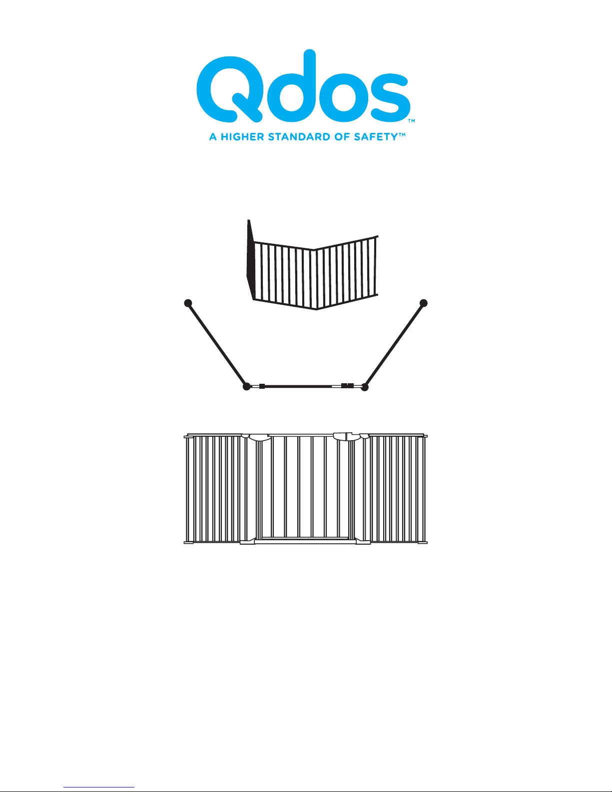
Construct-A-SafeGate
Height 30” (76 cm)
Maximum Opening 79” (202 cm) with included hardware
Add additional extensions to fit any opening
IMPORTANT: Qdos wants to keep your children safe
and for that we need you to do your part by carefully
reading and following the instructions below. Please read
through the instructions before starting the installation.
For installation videos and FAQ go to: QdosSafety.com
Page 2
2 3
IMPORTANT!
PLEASE READ AND FOLLOW THESE INSTRUCTIONS
CAREFULLY AND KEEP FOR FUTURE REFERENCE
When installed between two strong and rigid surfaces
and according to these instructions, this gate has been
tested to meet or exceed the following Safety Standards,
US- ASTM F-1004, Canada- SOR/90-39, and EuropeanEN 1930.
WARNING
• To prevent serious injury or death, securely
install gate and use according to manufacturer’s
instructions.
• Install according to manufacturer’s instructions
• Intended for use with children from 6 months up
to 24 months of age.
• NEVER use this gate immediately at top of stairs
as the bottom cross bar creates a tripping hazard.
• NEVER use to keep child away from pool.
• NEVER use with a child able to climb over or
dislodge/open the gate.
• This product will not necessarily prevent all
accidents. NEVER leave child unattended.
• Use only with the locking mechanism securely
engaged.
• Regularly check all hardware and do not use if any
part of gate is broken or missing.
• NEVER step or climb over the gate, always open
to pass through.
• For indoor use only.
• Fits openings up to 79” (200 cm)
HELP?
To help you install your gate quickly and easily, please go
to qdossafety.com for installation videos and FAQ’s to help
you succeed. You may also contact our customer service at
[email protected] or by phone at 800-593-5522.
MAINTENANCE AND CLEANING
Check the gate regularly to ensure all the hardware and
mountings are tightened. Clean using a mild soap and
wipe with a damp cloth.
WARRANTY
Your Qdos product is warranted to be free from
manufacturing defects in material or workmanship for
a period of 1 year from date of purchase, when used
under normal conditions and in compliance with these
instructions.
Qdos will either repair, or at its option replace, free of
charge, any parts necessary to correct any defect in
material or workmanship during the warranty period.
USE LOCATIONS
This Construct-A-SafeGate is the “Starter Kit” that can
either be used as is or with multiple extensions which
can be purchased seperately and added to provide
protection in dicult places like:
- Around bottom of stairs where it is hard or impossible
to mount a traditional gate
- Around 2 staircases with 1 going up and 1 going down
- Block o wide openings, either inside the opening or in
front of the opening, where a traditional gate won’t work.
- Around wood stoves, hearths and fireplaces
- As a freestanding playard when linked to itself
- And more
!
Page 3
4 5
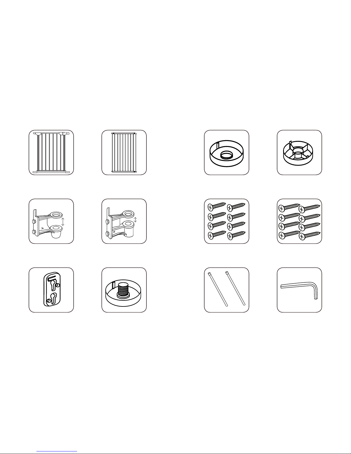
1x Door Section 1x Under Hinge Cover
2x Wall Bracket A
with bigger (1.5”/38 mm)
opening
8x Short 3/4” (19 mm)
Screws
8x Long 1.5” (38 mm)
Screws
2x Connecting
Spindles
4x Wall Plates
2 x Side Panels 2x Top Hinge Covers
2x Wall Bracket B
with smaller (1”/25 mm)
opening
1x Bottom Hinge Cover with
threaded post
1x Allen Wrench
PART LIST:
A
Small
opening
Large
opening
B
Page 4
6 7
IMPORTANT
When installing the gate in front of stairs, place it at least
24” (60 cm) from the top or bottom step.
When installed in front of a fireplace place it at least 30”
(75 cm) away from the fire.
EXTENSION AND DOOR KITS AVAILABLE
There are two additional Extension Kit Sizes and a Door
Kit that are available, each sold individually.
Construct-A-SafeGate Short Extension– 8” (20 cm)
Construct-A-SafeGate Long Extension– 24” (60 cm)
Construct-A-SafeGate Door Section- 31.5” (80 cm)
OPENING SIZE
Thanks to the complete flexibility of the ConstructA-SafeGate and the extension kits available, it can be
configured in endless ways and sizes to literally fit any
size and shape of opening.
ASSEMBLY
General
The following assembly instructions work for all sections
and extensions of the Construct-A-SafeGate. The sections
and extensions can be assembled and reassembled in any
order to fit the location.
Step 1
Determine the width of the area you need to protect, and
whether or not the 79 inch “Starter Kit” is enough, or if
you need to purchase additional extensions.
Step 2
Decide where you
want the Door
Section located in
the gate and also
which way you want
the door to swing.
Normally it’s most
convenient to have
the door in the
center or near the
center.
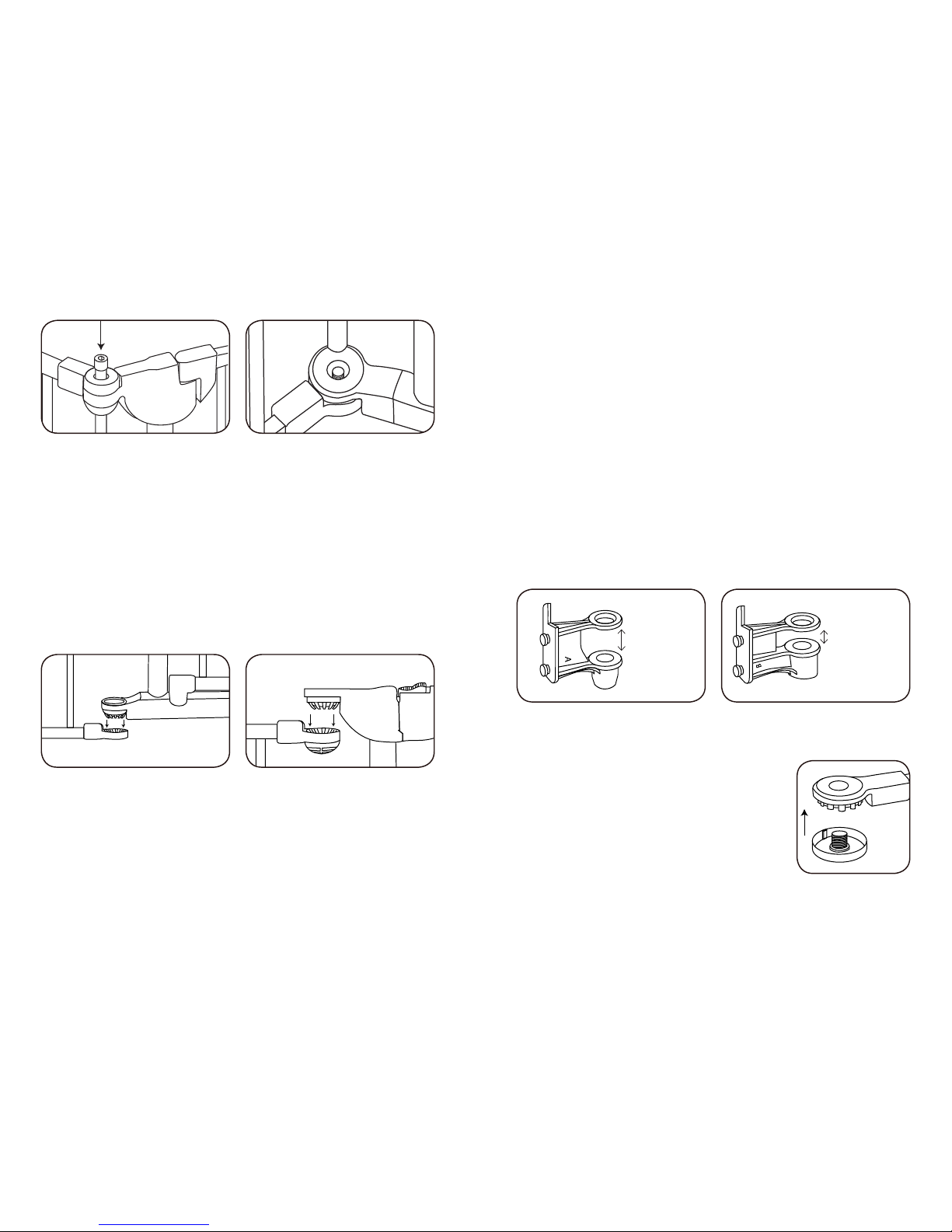
Step 3
On the hinge side of the Door Section, position an
Extension Panel with the flush hinge to nest with the
open hinge on the door section. Position at the desired
angle.
Insert the Connecting Spindle with the shiny end and the
Allen Wrench opening toward the the top. The bottom of
the Connecting Spindle is threaded and will fit onto the
threaded post in the lower hinge.
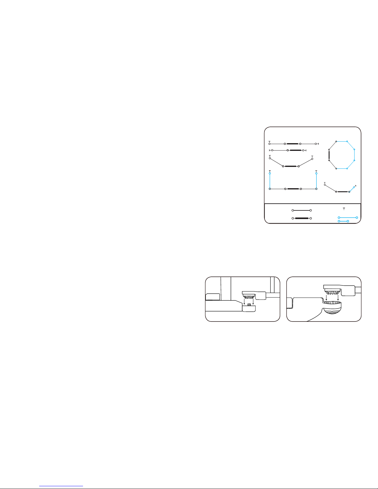
Examples:
Extension
Door Section
Wall Mount
Purchased Additional
Extension
Flush hinge
Open hinge
Floor Top
Page 5
8 9
MOUNTING TO THE WALL
The Construct-A-Gate must be secured to a wall, except
when used as a free standing playard.
Always secure the gate with both the top and bottom
Wall Brackets.
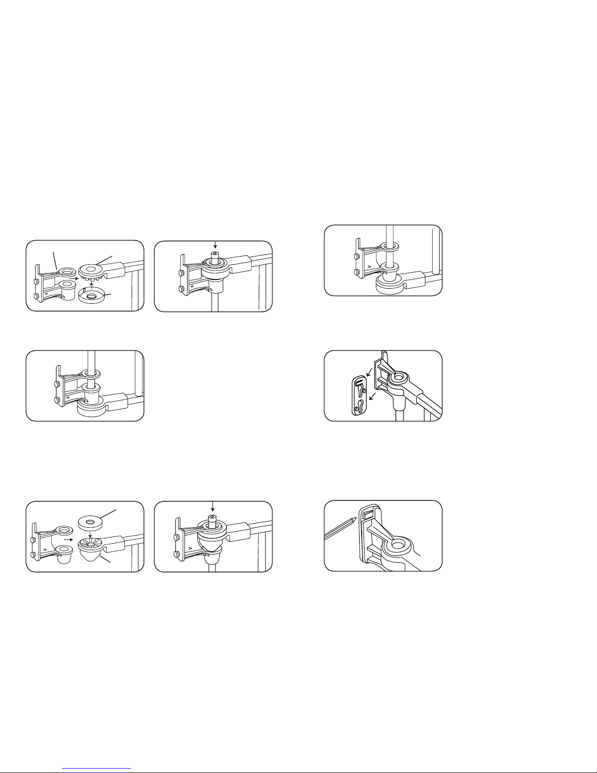
Step 6
Notice that there are two sets of Wall Brackets. Two with
bigger spacing (marked A) and two with a smaller spacing
(marked B). You will be using the two A’s on one side of
the gate and the two B’s on the other.
Step 7
Start with the end of the gate with the
“flat” hinges sticking out. Position the
Bottom Hinge Cover with the threaded
post under bottom hinge.
Only screw the Connecting Spindle in partially by hand
to allow possible angle adjustments of the gate without
having to disassemble.
Step 4
Repeat Step 3 on the locking side of the door Section,
by sliding the open hinge on the Extension in under the
flush hinge on the Door Section
Insert Connecting Spindle and only screw partially.
Step 5
Repeat Step 3 and 4 for any additional Extensions
needed.
Floor Top
Flush hinge
Open hinge
with threaded
post
Bottom
Hinge
Cover
A
Small
opening
Large
opening
B
Page 6
10 11
Insert the Under Hinge Cover on the Top Hinge on the
same side of the gate, then slide Wall Bracket B over the
top hinge and insert the Connecting Spindle.
Slide the second Wall Bracket B onto the Connecting
Spindle. Hand tighten the Connecting Spindle.
Step 8
For the other end of the gate with the “recessed” hinges,
you will use Hinge Bracket A both at the top and bottom.
Place the Top of Hinge Covers on both the top and
bottom hinges. Slide Wall Bracket A over the top hinge
and insert Connecting Spindle.
Slide the second Wall Bracket A onto the Connecting
Spindle with the cone shaped end down.
Step 9
Attach the Wall Plates to the Wall Brackets.
Step 10
Position the gate in the desired position and rotate Wall
Brackets to be flush with the wall. Using a pencil carefully
mark the position of each Wall Plate. The lower Wall
Brackets, these can be slid up on the Connecting Spindle
to avoid interfering with a baseboard if present.
Wall Bracket B
Under
Hinge
Cover
Wall Bracket B
Flat hinge
Wall Bracket A Top
Hinge
Cover
Recessed hinge
Wall Bracket A
Page 7
12 13
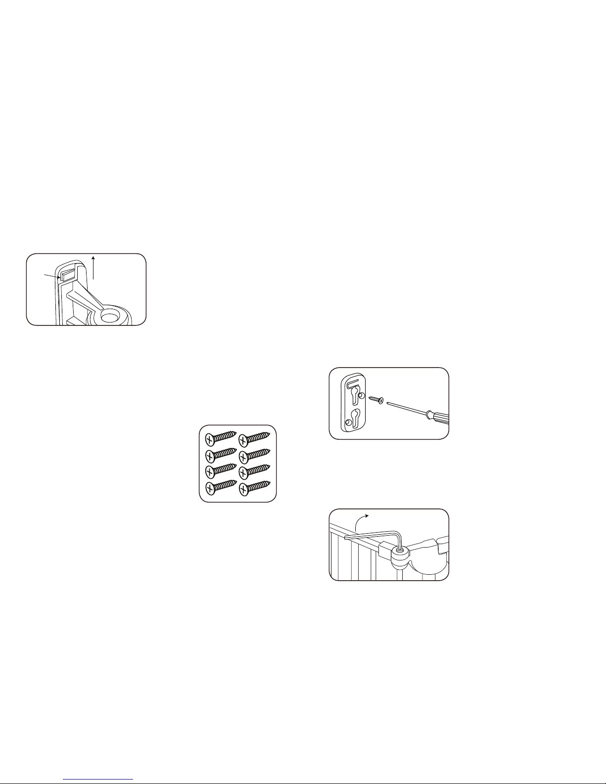
Step 11
Remove the Wall Plates from the Wall Brackets by
depressing the locking tab.
Place the Wall Plate inside the markings on the wall with
the locking tab at the top and mark the screw holes (they
are all identical). After this you can erase the markings
for the positioning of the Wall Plates from the wall.
IMPORTANT:
REGARDING THE INCLUDED MOUNTING SCREWS!
Before marking where to attach the
gate, make sure you have chosen a
solid surface for mounting the gate
to. The included screws are intended
for the following locations.
Directly into wood
The Short Screws 3/4” (19 mm) are
used when mounting directly into wood, for example in
a door frame or other framed opening. If installing into
hardwood, first drill a pilot hole.
Into a stud behind drywall
Use a studfinder to locate where there is a stud behind
the drywall. Then use the Long Screws 1.5” (38 mm) to
mount the gate into the stud.
Any other surface
If mounting into drywall, brick or other surface, use
only the appropriate hardware for that surface. Consult
with a certified child proofer, a handyman or your local
hardware store if you are unsure.
Step 12
Attach the four Wall Plates, by using the supplied wood
screws or other appropriate hardware as needed.
Step 13
Once you are satisfied with the installation and all angles
are correct tighten all Connecting Spindles by hand and
secure them by using the included Allen Wrench.
Push and Lift
Page 8
14 15
FREE STANDING PLAYARD
To assemble as a free standing playard begin by
following Steps 1 through 5. You then connect the ends
of the enclosure together as instructed.
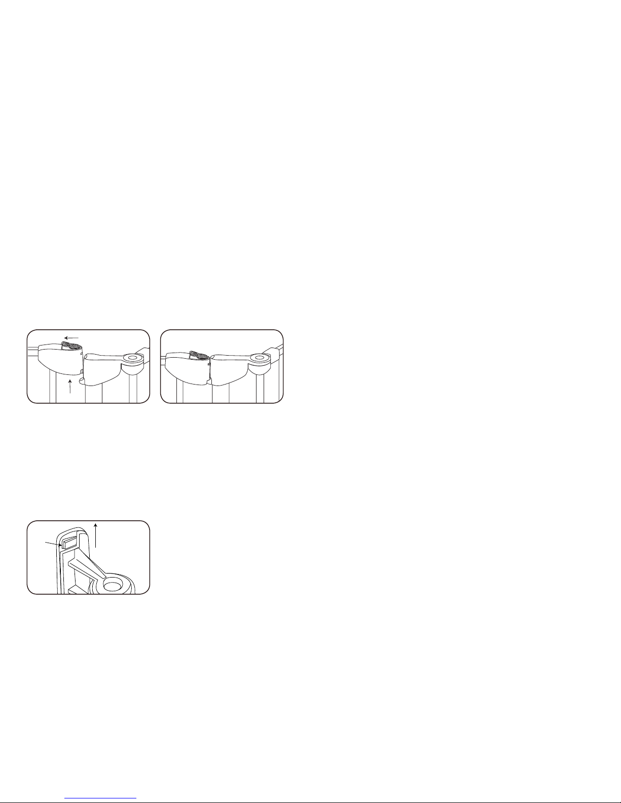
GATE OPERATION
To open – Slide locking button back and at the same time
lift the door.
To close – Position door parallel with frame and push
door down to lock.
REMOVING GATE FROM WALL
To remove the gate from the wall, press the locking tab
on the Wall Plates and lift gate up.
Start by releasing the two bottom Wall Brackets, as they
can slide up on the tube once released. Then release the
top Wall Brackets.
1
2
Locked
Push and Lift
Page 9

Distributed by Regal Lager, Inc.
Kennesaw, GA 30144 USA
1-800-593-5522 • www.QdosSafety.com
©2018 Qdos All rights reserved.
Qdos is a trademark of Regal Lager, Inc.
Made in China
05/2018
 Loading...