

Last updated : 2012.09.12
MODEL : QVI-LVTX-1CH-V7 / Product code : LVTX-1CH-1201-003
MASERATI
Specification & Installation
Your best partner for better driving
Contents
1. Before installation
1.1 Main specification
1.2 Features
1.3 System diagram
1.4 Components
1.5 Exterior
2. Setup
2.1 DIP switch
2.2 Remote control
2.3.1 OSD (on screen display)
2.3.2 OSD (on screen display)
2.4 Factory mode
2.5 Parking Guide line setting
2.6 DVD, DTV model selection
3. Installation
3.1 Installation diagram
3.2 Cautions on installation
3.3 Installation
3
4
5
6
7
8
9
10
11
12
13
14
15
16
17
4. Troubleshooting
www.qdis.co.kr
19
2

1.1 Main specification
1. Product composition
Multimedia Interface * 1ea
Sub-board * 1ea
2. MULTIMEDIA INTERFACE input spec.
3 * A/V (NTST&PAL) input
1 * CVBS (rear camera) input. (rear camera source)
1 * Analog RGB
1 * LCD input (car system input)
3. MULTIMEDIA INTERFACE output spec.
1 * LCD output(LCD Operation)
1 * Audio OUTPUT
2 * CVBS OUTPUT(Video Out for installing Headrest monitor)
4. POWER spec.
Input power : 8VDC ~ 16VDC
Consumption power : 4WATT (in maximum level)
5. Switch input mode
- Input video skip function : able to select whether to use the respective input video sources or not via DIP switch.
- Able to change input modes via the remote control.
- Able to switch modes via the Toggle switch.
- Able to switch modes via Original button of the car through CAN.
www.qdis.co.kr
3

1.2 Features
- Controllable displayed position of each external video sources on RGB,
A/V modes.
- Possible to move the displayed position of DVD, Navigation.
- Improved Display Screen (convenience-oriented Interfaces for users)
- Add a safe function (show the main screen while driving)
- Able to switch videos and select DTV channel via the original buttons
- Compatible cars
Maserati Gran Turismo 2008~
www.qdis.co.kr
4
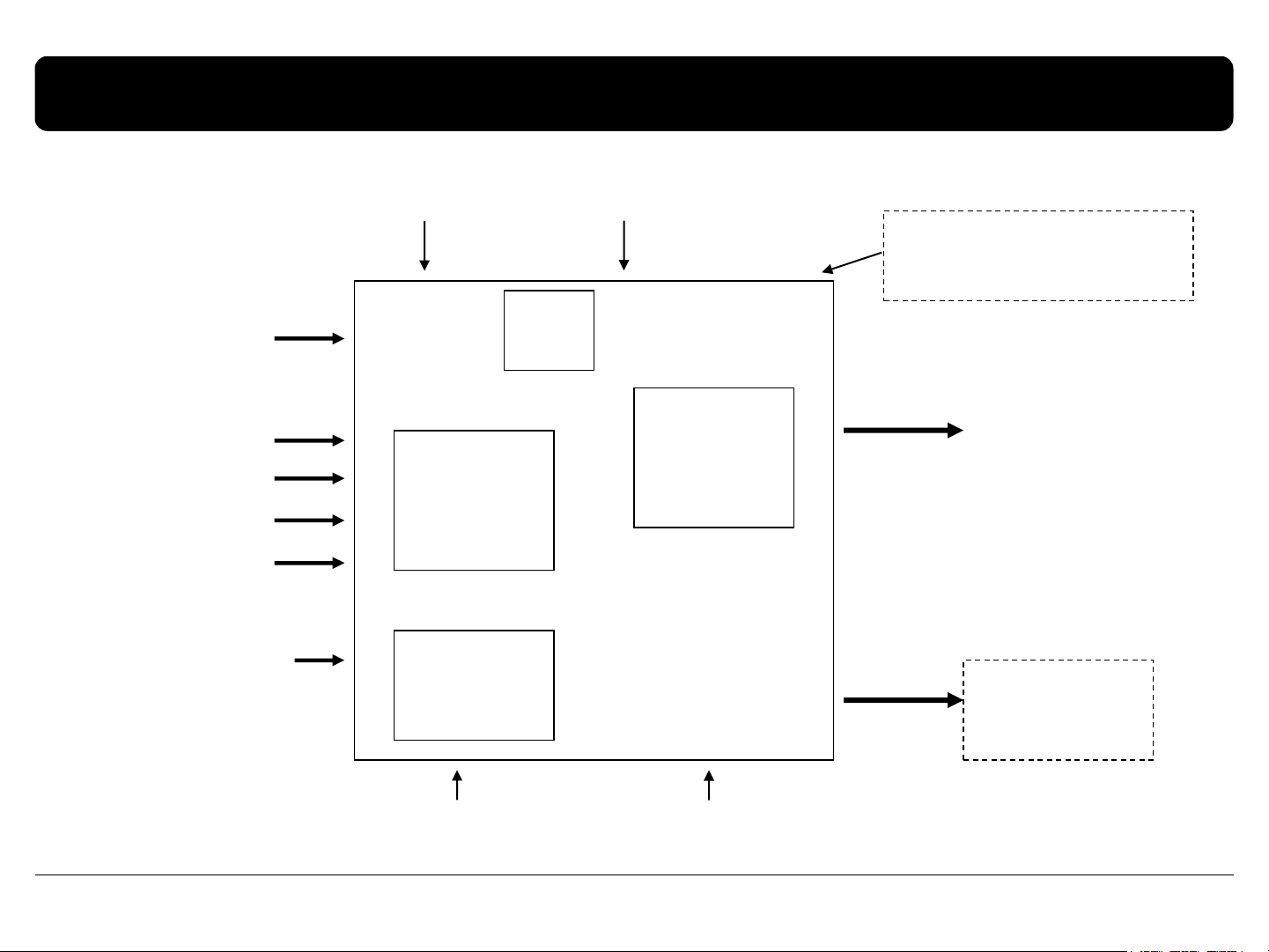
1.3 System diagram
NAVIGATION Input
(Analog RGB)
A/V 1
A/V 2
A/V 3
CVBS
(Rear camera)
Car Screen Input
(CAR MAIN BOARD)
Remote control
VIDEO
CIRCUIT
POWER
CIRCUIT
Switch for source toggle
MCU
VIDEO MUX
DISPLAY
A/V OUT
OEM Navi Button (Can Signal)
Car Installation
OEM LCD
HEADREST
MONITOR
www.qdis.co.kr
Power Input
(+8VDC ~ +16VDC)
Dip S/W
5
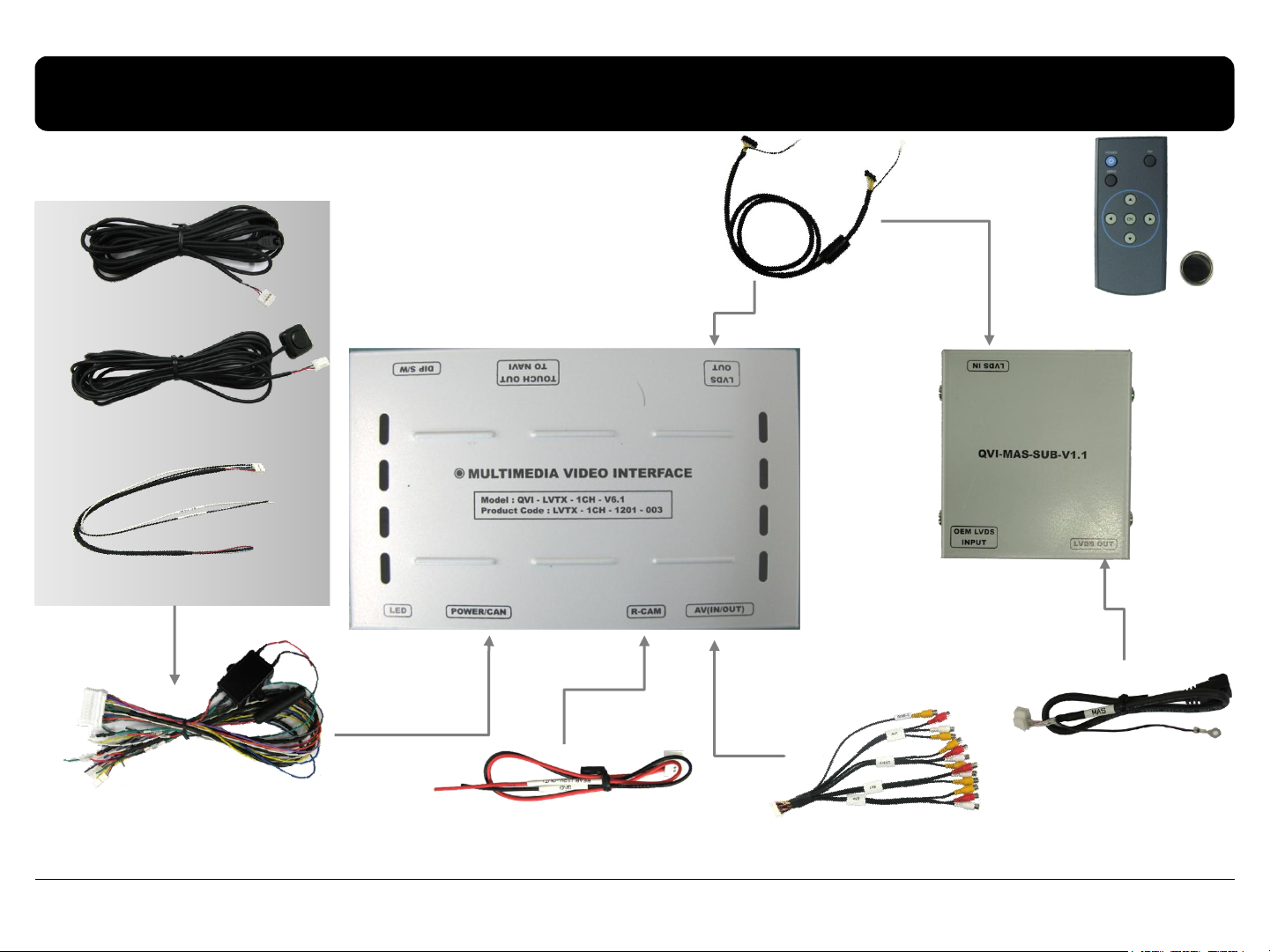
1.4 Components
LVDS cable * 1EA
(HLVDSC0014)
IR cable * 1ea
(HIRCAB0002)
MODE cable * 1ea
(HARETC0001)
RGB cable * 1ea
(HNAVIC0004)
POWER cable (24P) * 1ea
(HPOWER0011)
REAR CAMERA POWER cable * 1ea
(HARETC0002)
REMOTE CONTROL * 1ea
(REMOTE0001)
SUB BOARD* 1ea
LCD cable * 1ea
(HLVDSC0022)
A/V cable * 1ea
(HAVCAB0002)
www.qdis.co.kr
6

1.6 Original buttons in car
After Connecting original can wire in car with offered can wire, user can use original button
Mode switching
Press long : Switching mode
Press short : go to original
mode directly
DTV Channel DOWN
DTV
Channel UP
www.qdis.co.kr
7

2.1 DIP switch
PIN
Function
Dip S/W Selection
1
2
3
4
5
6
7
8
※ ON : DOWN / OFF : UP
RGB INPUT MUTE
A/V 1 MUTE
A/V 2 MUTE
A/V 3 MUTE
Rear Mode
ON : Skipping RGB Mode
OFF : RGB Display
ON : Skipping A/V 1
OFF : A/V1 Display
ON : Skipping A/V 2
OFF : A/V2 Display
ON : Skipping A/V 3
OFF : A/V3 Display
N.C
N.C
ON : External Rear Camera
OFF : OEM Rear Camera
N.C
※ DIP S/W usage example
- Input Mode : A/V3, Navigation (RGB)
- When original Navigation is not installed
- Rear camera : When to be installed on CVBS 4
▷ DIP S/W : 1 OFF
▷ DIP S/W : 2,3 ON (INPUT MODE SKIP)
▷ DIP S/W : 4 OFF (displaying A/V3)
▷ DIP S/W : 5,6 - OFF
▷ DIP S/W : 7 - ON (Displaying CVBS4)
▷ DIP S/W : 8 - OFF
※ Please make sure to disconnect the power cable of the interface and reconnect
the power cable again to apply the dip switch setting whenever changing DIP switch.
Otherwise, DIP switch setting will not be applied.
www.qdis.co.kr
8

2.2 Remote control
Key
Function
POWER & PIP Unavailable
MENU Activating OSD menu
OK Making a selection, changing image display
▲ Moving upward
▼ Moving downward
Moving leftward
◀
(If you press this button 5 seconds long, you can get access to
the factory mode.)
Moving rightward
▶
*FACTORY MODE (Interface setting for installer)
: Operated by pressing ▲ → ▼ → ▲ →MENU button or press ◀ more than 5seconds long on the remote control.
(If you press this button 2 seconds long, you can reset all the
data about user environment.)
www.qdis.co.kr
9

2.3.1 OSD (on screen display)
Analog RGB Mode
IMAGE
* BRIGHTNESS
* CONTRAST
* SHARPNESS
* USER IMAGE
: Selecting one among
4 color options.
www.qdis.co.kr
COLOR
* RED : Adjusting red
* GREEN : Adjusting green
* BLUE : Adjusting blue
* USER COLOR
: Selecting a color option
among set color options
OSD
* LANGUAGE :Choosing
OSD language while using
Touch OSD
(English, Chinese only)
* TRANS : Adjusting
transparency of OSD
* H_POSITION, V_POSITION :
Positioning OSD menu
UTIL
* FACTORY RESET :
OSD MENU RESET
10

2.3.2 OSD (on screen display)
Video mode
IMAGE
* BRIGHTNESS
* CONTRAST
* SATURATION
* HUE
* SHARPNESS
* USER IMAGE
: Selecting one among 4 color
options.
www.qdis.co.kr
OSD
* LANGUAGE : Choosing OSD
language while using Touch OSD
(English, Chinese only)
* TRANS : Adjusting transparency of
OSD
* H-POSITION
: moving in horizontal direction
* V-POSITION
: moving in vertical direction
UTIL
* FACTORY RESET : OSD MENU RESET
11

2.4 Factory mode
FACTORY mode – Press ◀ button 5 seconds long on the remote control.
IMAGE
Adjusting the position of
navigation
* H-POSITION
: moving in horizontal direction
* V-POSITION
: moving in vertical direction
* NAVI MODEL : Do not use
* AVOUT SELECT : DEFAULT, AV1,
AV2, AV3
www.qdis.co.kr
PARK
* PARK ENABLE : Setup of rear view
parking guide line
* PARK SETUP : Control over position
of rear view parking guide line
* SAFE ENABLE : To select whether
to use SAFE function(NOT to allow
watch video while driving) or not
UTIL
* CALIBRATION : Do not use
* IR MEMORY : Do not use
* DVD TYPE :
Setup for the type of DVD
* DTV TYPE :
Setup for the type of DTV
* JOG SUTTLE : Do not use
* FACTORY RESET : To reset all the
value in factory mode
12

2.5 Parking guide line setting
FACTORY mode – Press ◀ button 5 seconds long on the remote control.
PARK
* PARK ENABLE : Selecting whether to
display the parking guide line or not
on rear gear (default : OFF)
* PARK SETUP : Adjusting the position of
the parking guide line (available in
PARK SETUP -> V-POSITION, H-POSITION)
* SAFE ENABLE : In case of Connecting
“Safe” wire from the power cable to
the hand break,
ENABLE – OEM Picture displays in Drive
gear position
DISABLE – No display locked in any
gear position
www.qdis.co.kr
PARK - ENABLE
A. If you set ‘PARK ENABLE’ as
“ON” state, there will be the rear
view parking guide line.
(as shown left picture)
B. Press the OK button of remote
controller, ‘’H_POS’’ will be
shown on the right and control
moving in horizontal direction.
PARK - ENABLE
A. Press the OK button of remote
control one more, ‘’V_POS’’ will
be shown on the right and control
moving in vertical direction.
13

2.6 DVD, DTV model selection
DVD TYPE
UTIL – DVD/DTV TYPE
If DVD/DTV type that you want to use is not NECVOX or SANYO, you have to register values of the remote
controller that you want to use in the “IR MEMORY” section and set the “DVD TYPE”/”DTV TYPE” to “USER”.
Unless you do this process after saving the data, you can NOT control DVD/DTV via touch screen.
DVD TYPE : NEC/SANYO, DV-108, SANYO-1, SANYO-2, USER
DTV TYPE : PIONEER/PANASONIC, USER, CMMB
※ If you enter data in ”IR MEMORY” section in FACTORY mode, “DVD TYPE”/ “DTV TYPE” will automatically be saved to “USER”.
www.qdis.co.kr
DTV TYPE
14

3.1 Installation diagram
CAN
※ Connecting CAN
HIGH(Brown+Green) in interface with
CAN HIGH(Black+Pink) in the car
※ Connecting CAN LOW(Green) in
interface with CAN LOW(White+Pink) in
the car
CAN High
CAN Low
AUX-ON (N.C)
RGB
CAN-L
CAN-H
IR-AV3 (DTV)
IR-AV2 (DVD)
IR-AV1 (NAVI)
PARKING (SAFE)
Control Box
MODE : Toggle S/W
Original LCD Cable
REAR
OPT2 (N.C)
IR
PB12 (N.C)
GPIO-ZO : MMI
GND
ACC
Offered LVDS Cable
The behind of Monitor
Original
offered LCD cable
REAR (9V OUT)
AV1
GND
REAR C
AV/OUT
AV2
AV3
Audio R
Audio L
Video
Monitor
www.qdis.co.kr
15

3.2 Cautions on installation
Ignition key should be taken off before starting installation, interface power connection must
be the last step in installation.
Power cable should be separated when connecting interface.
Should be no any electronic devices or magnetic pole around installation place.
All steps of installation should be done by well-trained specialist.
Dismantling without manufacturer’s permission can not be guaranteed, (No permission to
break attached label on the board.)
Kindly check all parts are in the box, when receiving the product, if anything missing, inform to
the supplier or manufacturer.
According to our sales policy, any problems caused by user’s mistake, careless can not be
guaranteed.
It may not work on a camera with 12V
www.qdis.co.kr
16

3.3 Installation
Connecting with monitor
Command
①
Offered LVDS cable
②
Original LVDS cable
Behind of the
Monitor
③
Offered LCD out cable
1.Connect offered LVDS cable into “LVDS IN” in Sub-board and “LVDS OUT” in interface
2. After Separating original LVDS cable from the monitor, connect into
OEM LVDS INPUT” in sub board
3. Offered LCD OUT cable connect to the behind of monitor and “LVDS OUT” in sub board

3.3 Installation
Connecting with CAN wire
Control box
Original CAN-Low
Original CAN-High
Offered CAN-High
Power cable
Offered CAN-Low
1. Connecting CAN HIGH(Brown+Green) in interface with CAN HIGH(Black+Pink) in the car
2. Connecting CAN LOW(Green) in interface with CAN LOW(White+Pink) in the car

4. Troubleshooting
Q. I can not switch A/V sources
A. Check IR or Ground cable connection. Check LED lamps in the interface, if it is not on, check power cable.
Q. All I got on the screen is black.
A. Check second LED lamp of the interface is on, if not, check A/V sources connected are working well. (Second lamp indicates AV
sources connected works well.) Check interface connection has been done well.
Q. Displayed image color is not proper (too dim or not suitable color)
A. Try to select “INITIAL” in OSD menu, if it does not work, inform to manufacturer.)
Q. I can watch the rear camera on the screen
A. Set the DIP switch #7 as state “ON”.
Q. Unwanted A/V mode is displayed. (A/V source switching order : OEM->RGB->AV1->AV2->AV3)
A. Check DIP Switch Setting.
Q. OEM image is not displayed.
A. Check interface’s LCD In/Out cable connection. If the status keeps on, inform to manufacturer.
Q. Screen only displays white color.
A. Check LCD out cable is connected well, if this status keeps, inform to manufacturer.
Q. After setting PIP function, I got only half OEM image at the right in the screen.
A. This is not an error, just caused by user’s setting mistake, user should set to
“Split Screen” in the OEM menu.
Q. Rear CAM does not appear, when car is in reverse after CAN wiring.
A. Operate “FACTORY MODE” like left picture, then select “UTIL Rear Select” If it is set as “LAMP”, change it to “CAN” by remote or
keypad.
※ LAMP : In case of connecting “Rear-C” wire of Power Cable to Rear Lamp in vehicle.
CAN : In case of detecting Rear Cam thru CAN signal. (CAN must be wired)
Q. After moving gear to “P” or “D” from “Reverse”, I can’t get navigation, but half PDC Image in the screen.
A. Once, you starts driving, the screen displays navigation right away, this is not an system error.
www.qdis.co.kr
19
 Loading...