

Page 1

P6I440BX/B1S
SETUP DELLA SCHEDA SPEEDEASY
Procedura di installazione:
1. Inserite il microprocessore Pentium®II/ Intel® CeleronTM come da istruzioni.
2. Modificate la configuraz ione del computer e ripristinate il sistema.
3. Premete il tasto <Del> e accend ete il com puter p er entrar e nel set up BIOS.
4. Entrate nel menu “Spee dEasy C PU* SET UP” pe r regolar e la veloc it… del
microprocessore.
Nota: se non regolate la v elocità del microprocessore, il sistema funzionerà
con le regolazioni standard (Microprocessore da 200MHz con velocità di
“host bus” da 100MHz e microprocess ore da 133MHz con velocità di “host
bus” da 66M Hz).
1
5. Salvate e uscite dal Setu p BIOS, e fate rip artire il computer.
*CPU= microprocessore
Manual for P6I440BX/B1S
9
Page 2

Spiegazioni tecniche sul microprocesore SpeedEasy
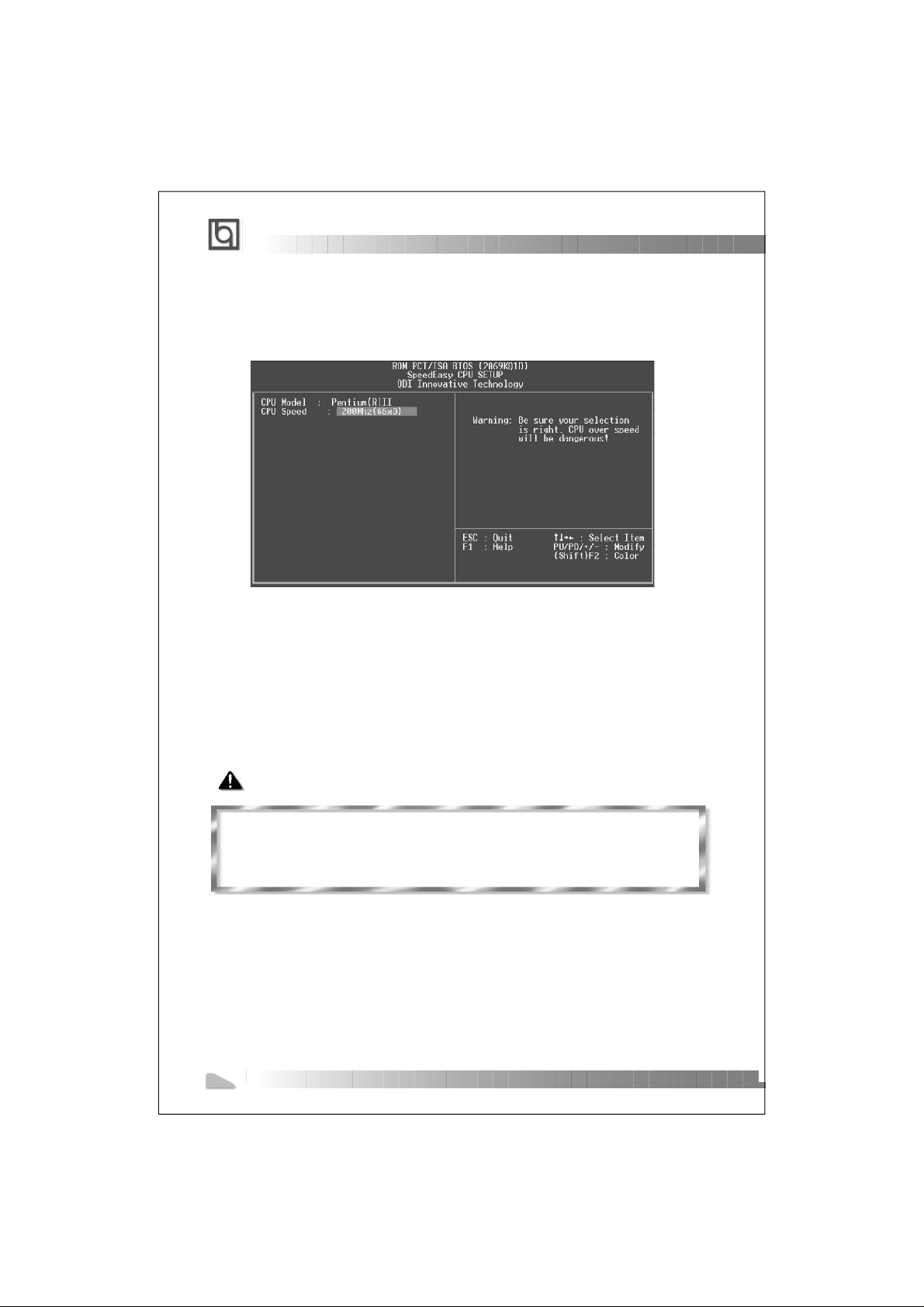
Menu del Setup del Microprocessore SpeedEasy
Selezionare <SpeedEasy CPU SETUP> dal menu principale ed entrare nel segu ente
sottomenu:
Figure -1 Menu del Setup d el Micro processo re Speed Easy
I1 sistema BIOS Vi forniràu na serie di valori base per la selezi one del microprocessore al
posto della regolazione jum per (de ll’accopp iamento ). Potete selezion are manu almente la
velocità del microprocessor e sulla s chermat a “Speed Easy CP U SETU P”.
Avvertenza:
non dovete regolare la freq uenza del microprocessore pi alta di quella predisposa,
altrimenti la casa produttri ce non si farà car ico di eve ntuali da nni al mi corproce ssore.
10
Manual for P6I440BX/B1S
Page 3

³ÌÐò :
P6I440BX/B1S
SpeedEasy ¿ìËÙ°²×°Ö¸ÄÏ
1.ÕýÈ·µØ²åÈë Pentium® II»ò Intel
®
Celeron
TM
ÖÐÑë´¦ÀíÆ÷¡£
2.²еИлЖдЛыЕдЦГ ,ЧйЧ°³ЙНкХыµДО¢»ъПµН³ .
3.¿ª¶¯ÏµÍ³µçÔ´²¢°´×¡ <Del>¼ü£¬ ½øÈë BIOSÉèÖóÌÐò¡£
4.½øÈë ¡° Spee d Easy CPU SETUP¡± ²Ëµ¥£¬ ТФµч½ЪЦРСл´¦АнЖчµДЛЩ¶И¡£
×¢Òâ :Иф²»µч½ЪЦРСл´¦АнЖчµДЛЩ¶И£¬ ПµН³½«ТФФ¤Йи¶¨µДЛЩ¶ИФЛРР £¨¶ФУЪЧЬПЯЖµВКОª
100MHzµÄ CPU, Ϊ 200MHz£» ¶ФУЪЧЬПЯЖµВКОª 66MHzµÄ CPU, Ϊ 133MHz£©¡£
5. ´æ´¢É趨ֵ£¬ Í˳ö BIOS£¬ ПµН³¾Н¿ЙТФ°´ДгЙи¶¨µДЛЩ¶ИФЛРРБЛ¡£
Manual for P6I440BX/B1S
11
Page 4
SpeedEasy ·½Ê½½éÉÜ
Speed E a s y ЦРСл´¦АнЖчЙи¶¨²Лµ¥
´УЦчЙиЦГ²Лµ¥ЦРС¡Фс<SpeedEa sy CPU SETUP>ÏȻáá½øÈë´Î²Ëµ¥£º
ͼ£- 1 Speed EasyЦРСл´¦АнЖчЙи¶¨ПоД¿µ¥
BIOSОªДгµДЦРСл´¦АнЖчМб¹©Т»Чй»щ±¾С¡По£¬ТФ´ъМж´«Н³µДМшПЯ(jumper)·½К½£¬К¹
Дг¿ЙТФФЪ ¡°SpeedEasy CPU SETUP¡±²Лµ¥ЙП£¬ ОªЦРСл´¦АнЖчС¡ФсХэИ·µД¹¤ЧчЖµ
ÂÊ¡£
¾¯¸æ £º
ÇëÎð½«ÖÐÑë´¦ÀíÆ÷µÄƵÂʵ÷½ÚÖÁ¸ßì¶ÆäÕý³£¹¤×÷ƵÂÊ£¬·ñÔò±¾¹«Ë¾½«
²»»á¸ºÔðÓɴ˶ø²úÉúµÄÈκÎËð»Ù¡£
12
Manual for P6I440BX/B1S
Page 5

³ÌÐò £º
P6I440BX/B1S
SpeedEasy¿ìËÙ°²×°Ö¸ÄÏ
1.ÕýÈ·µØ²åÈë Pe n tium®II»ò Intel
®
Celeron
TM
ÖÐÑë´¦ÀíÆ÷¡£
2.²еИлЖдЛыЕдЦГ£¬ ЧйЧ°³ЙНкХыµДО¢»ъПµН³¡£
3.¿ªÆôϵͳµçÔ´£¬ ²¢ÇÒ°´×¡ <Del>¼ü ,½øÈë BIOSÉèÖóÌÐò¡£
4.½øÈë ¡° Spee d Easy CPU SETUP¡± ²Ëµ¥£¬ ТФµч½ЪЦРСл´¦АнЖчµДЛЩ¶И¡£
×¢Òâ £º Иф²»µч½ЪЦРСл´¦АнЖчµДЛЩ¶И£¬ ПµН³½«ТФФ¤ЙиµДЛЩ¶ИФЛРР (100Õ׺Õ×Ü
ÏßµÄ CPU»áÒÔ • 200ХЧºХФЛРР£¬ 66ХЧºХЧЬПЯµД CPU »áÒÔ 133ХЧºХФЛРР )¡£
5.´æ´¢É趨ֵ£¬ Í˳ö BIOS£¬ ПµН³¾Н¿ЙТФ°´ДгЙи¶¨µДЛЩ¶ИФЛРРБЛ¡£
Manual for P6I440BX/B1S
13
Page 6

SpeedEasy·½Ê½½éÉÜ
Speed E a sy ЦРСл´¦АнЖчЙи¶¨²Лµ¥
´УЦчЙиЦГ²Лµ¥ЦРС¡Фс <SpeedEas y CPU SETUP>Ï И»бб½шИлЧУ²Лµ¥ £º
ͼ£- 1 SpeedEasyЦРСл´¦АнЖчЙи¶¨ПоД¿µ¥
BIOSОªДгµДЦРСл´¦АнЖчМб¹©Т»Чй»щ±¾С¡По£¬ ТФ´ъМж´«Н³µДМшПЯ (jumper)·½Ê½£¬ ʹ
Дг¿ЙТФФЪ¡± SpeedEasy CPU SETUP” ²Ëµ¥ÉÏ£¬ ОªЦРСл´¦АнЖчС¡ФсХэИ·µД¹¤ЧчЖµВК¡£
¾¯¸æ £º
ÇëÎð½«ÖÐÑë´¦ÀíÆ÷µÄƵÂʵ÷½ÚÖÁ¸ßì¶ÆäÕý³£¹¤×÷ƵÂÊ£¬ ·ñÔò±¾¹«Ë¾½«²»»á¸ºÔð
Óɴ˶ø²úÉúµÄÈκÎËð»Ù¡£
14
Manual for P6I440BX/B1S
Page 7

Chapter 1
Chapter 1
Chapter 1
Introduction
Introduction
Overview
The P6I440BX/B1S green motherboard utilizes the Intel® 440BX AGPset and prov ides a
highly integrated solution fo r fully co mpatible, high performance PC/ATX platform . It pro vides
66MHz and 100MHz syste m bus su pport for all Intel Pentium® II and Ce leron
Both 66MHz/100MHz SDR AM with SPD an d 66MHz EDO DIMMs are supported. It also
provides advanced features such as wake-up on LAN, wake-up on internal/external modem and keyboard password power-on function. ManageEasy, our system mana gement
application is supplied to enable remote monitoring and configuration of the syste m.The
green function is in compliance with the ACPI specific ation. W ith the everlasting innovations
of QDI such as SpeedEasy , LogoEasy and SecurityEasy technologies, you get a powerful
corporate system.
TM
processors.
Key Features
Form factor
ATX form factor of 305mm x 190mm.
Microprocessor
Supports all Intel Pentium® II processors at 233/266/300/333MHz with 66MHz bu s
speed and 350/400/450MHz with 100MHz bus spe ed.
Supports all Intel® CeleronTM processors at 266/300/333 MHz with 66MHz bus
speed.
Supports 66MHz and 100M Hz hos t bus spe ed.
CPU core frequency = Bus speed x2.5, x3, x3.5, x4, x4.5, x5, x5.5
CPU core supply voltage a djustable from 1.3V to 3.5V through on- boar d switch ing
voltage regulator with VID(Voltage ID).
Chipset
®
Intel
440BX AGPset: 82443BX , 82371E B (PIIX 4E)
System mem ory
Provides three 168 pin 3.3 V unbuff ered DIMM sockets.
Supports both 66MHz/100M Hz SD RAMs w ith SPD and 66M Hz ED O DIMM s.
Minimum memory size is 8 MB, max imum m emory s ize is 76 8MB.
SDRAM 64 bit data interfa ce with E CC support.
Manual for P6I440BX/B1S
15
Page 8

Introduction
On-board IDE
Supports two PCI PIO and Bu s Maste r IDE p o rts.
Two fast IDE interfaces supporting four IDE devices including IDE hard disks and
CD - ROM drives.
Supports up to mode 4 timing.
Supports “Ultra DMA/33” Synchronous DMA mode tra nsferring up to 33 Mbytes/sec.
Integrated 16x32bit buffer for IDE PCI Burst Transfers .
On-board I/O
Use Winbond W83977EF super I/O chip.
One floppy port supporting up to two 3.5’’or 5.25” floppy drives with
360K/720K/1.2M/1.44M/2.88M format.
Two high speed 16550 fas t compat ible UAR Ts(COM1/COM2/ COM3/C OM4
selective) with 16-byte send/rec eive FIFOs.
One enabled parallel port a t the I/O address 378H/278H/3BCH with additional
bi-direction I/O capab ility and m ulti-mo de as SP P/EPP/ ECP (IEE E 1284 compliant).
Circuit protection provided, preventing damage to the parallel port when a
connected printer is powered up or operates at a higher voltage.
Supports LS-120 floppy disk drive.
All I/O ports can be enabled/disabled in the BIOS setup.
Advanced features
Provides Trend ChipAwayVirus® On Guard.
Provides on-board PS/2 mouse and PS/2 keyboard po rts.
Two USB ports supported.
Provides infrared interface.
Supports Windows 95/98 software power-down.
Supports external modem ring power-on.
Supports wake-up on LAN and wake-up on internal modem.
Supports auto fan off when the syst em enters suspend mode.
On-board LM80 supports system monitoring (monitors system temperature,volta ges,
chassis intrusion and fan s peed) (m anufacturing option).
On-board MAXIM1617 mo nitors the CPU tem peratu re. (manufacturing option)
Provides management ap plication such as ManageEasy and LDCM(LANDesk
Manager) (manufactur ing option).
Supports keyboard password power-on function.
Supports SecurityEasy fun ction (ma nufacturing option)
System status resumes after AC power failure.
16
Manual for P6I440BX/B1S
®
Client
Page 9

Chapter 1
BIOS
Licensed advanced AWARD BIOS, supports flash ROM BIOS with 2MB memory
size, plug and play ready.
Supports IDE CD-ROM or SCSI boot up.
Green function
Supports ACPI (Advanced Configur ation and Power Interface) and ODPM (OS
Directed Power Managem ent).
Supports three green modes: Doze, Standby and Sus pend.
Expansion slots
3 ISA slots and 4 PCI slots.
1 AGP Slot
Manual for P6I440BX/B1S
17
Page 10

-- This page is intentionally left blan k --
18
Manual for P6I440BX/B1S
Page 11

chapter 2
Chapter 2
Chapter 2
Installation Instructions
Installation Instructions
This section covers External Connectors, Jumper Set tings and Memory Configuration. Re fer to the motherboard layo ut chart for locations of all the jumpers, external connectors,
slots and I/O ports. Furthe rmore, th is sectio n lists all necessa ry connector pin assignments
for your reference. The par ticular state of the jumpers, connec tors and ports are illustrated
in the following figures. Before setting the jumpers or inserting these connectors, please
pay attention to the directio ns.
Be sure to unplug the AC power supply before adding or removing expansion
cards or other system peripherals, otherwise your motherboard and expan-
sion cards might be seriously damaged.
External Connectors
PS/2 Keyboard Connector, PS/2 Mouse Connector
PS/2 keyboard connector is for the usage of PS/2 key board. If using a standard AT size
keyboard, an adapter shou ld be use d to fit th is conne ctor. PS/ 2 mouse connect or is for the
usage of PS/2 mouse.
PS/2 Mou se Connector
PS/2 Keyboard Co nn ector
USB1, USB2
Two USB ports are available for connecting USB devices.
USB1
USB2
Parallel Port Connector and Serial Port Connector (UART1, UART2)
The parallel port connector can be connected to a parallel devi ce such as a printer, while
the serial port connectors c an be connected to serial port devices such as a serial port
mouse. You can enable/dis able the m and ch oose the IRQ or I/O address in “Integrated
Peripherals” from AWARD BIOS S ETUP.
Parallel Port
UART2
Manual for P6I440BX/B1S
UART1
19
Page 12

Installation Instruction
ATX Power Supply Connector & Power Switch (POWER)
Be sure to connect the power supply plug to this connector in its proper orientation. The
power switch (POWER) sh ould be connected to a momentary switch. When powering up
your system, first turn on the mechanical switch of the power supply (if one is provided),
then push once the power button. When powering off the system, you needn’t tur n off the
mechanical switch, just Push once* the power button.
ATX Power Supply Connector
5V 5V -5V GND GND GND PSON GND -12V 3.3V
20
12V 5VSB PS-OK GND 5V GND 5V GND 3.3V 3.3V
POWER
Note: * If you change “soft-off by PWR-BTTN” from default “Instant-off” to “Delay
4 Secs” in the “POWER M ANAGEMENT SETUP” section of the BIO S, the power
button shou ld be pressed f or more than 4 seconds before the system powers
down.
1
Hard Disk LED Connector (HD_LED)
The connector connects to the case’s IDE indicator L ED indicating the activity status of
IDE hard disk.
Reset Switch (RESET)
The connector connects to the case’s reset switch. Press the switch once, the system
resets.
Speaker Connector (SPEAKER)
The connector can be conn ected to the speaker on the case.
Power LED Connector (PWR_LED)
The power LED has three status. When no A C power supply is present, the LED is off.
When the system is in soft power-down status, the LED glows dimly. When the system
is powered up, the LED is on.
Key-Lock Connector (KEY_L)
The connector can be conn ected to the keyb oard loc k switch on the case for locking the
keyboard.
20
Manual for P6I440BX/B1S
Page 13

chapter 2
Green LED Connector (GREEN_LED)
The LED connected to this header shows the status of the system as described below:
LED Status System S tatus
Off No AC power supply.
On The system is in power-up status.
Flashing at a frequency of about 1.5Hz The system is in soft powe r-down s tatus.
Flashing at a frequency of about 0.5Hz The system is in Green Mode.
Flashing at a frequency of about 1/6Hz The system is in Lock status.
Hardware Green Connector (SLEEP)
If the SecurityEasy function is enabled, push once the switch connected to this he ader
and the system will enter lo ck statu s. If the l ock function is disabled, push once the
switch, the system enters suspend mode.
S
P
R
L
E
D
+
H
D
_
L
E
D
K
L
E
G
D
E
S
N
A
D
E
T
D
A
T
R
E
S
E
T
P
O
W
G
G
V
N
C
N
E
N
C
D
R
D
C
S
P
P
O
E
W
A
K
E
E
R
R
K
E
Y
L
L
L
L
E
D
+
P
W
R
_
L
E
D
G
E
E
O
N
D
D
C
K
D
-
K
E
Y
_
L
S
L
L
L
L
E
E
E
G
E
D
D
D
E
+
N
P
D
-
-
G
S
R
L
E
E
E
E
N
P
_
L
E
D
Infrared Header (IrDA)
This connector supports wireless transmitting and receiving. If using this function, set
‘Serial Port 2 Mode’ to IrD A or AS KIR and configur e the set tings from the ‘I NTEGRA TED
PERIPHERALS’ section o f the BIO S.
NC
Manual for P6I440BX/B1S
IRRX
GND
VCC
IRTXVCC
21
Page 14

Installation Instruction
Fan Connector (CPUFAN, CHSFAN)
These two fans are controllable. They will be automatically turned off after the system
enters suspend mode. You also can choose not to tu rn the CP UFAN o ff by set ting “CPU FAN
Off In Suspend” as Disab led in the “POWER MANAG EMEN T SETU P” secti on of the BIOS.
CPUFAN
FAN GND(Controllable)
+12V
SENSE
+12V
FAN GND
SENSE
CHSFAN
Wake-Up On LAN (WOL)
Through the Wake-Up On LAN function, a wake event occurring from the network can
wake up the system. If this function is to be used, please be sure an ATX 2.01 power
supply of which 5VSB line is capable of delivering 720mA, and a LAN adapter which
supports this function are u sed. The n conne ct this he ader to t he relevant connector on the
LAN adapter, set “Wake U p On LA N” as E nabled in the “POWER MA NAGEM ENT SETUP”
section of the BIOS. Save & exit, th en boot the operating system once to make sure this
function takes effect.
+5V standby
1
Signal for w aking up (active high)
GND
Wake-Up On Internal Modem (WOM)
Through the Wake-Up On Internal Modem function, the system which is in the power-off
status can be powered on by a ring signal received from the inte rnal mod em. If this function
is to be used, be sure an internal modem card which s upports the function is used. Then
connect this header to the relevant connector on the m odem c ard, set “ Resume by Ring” to
Enabled in the “POWER M ANAGE MENT SETUP” section of the BIOS. Save & exit, then boot
the operating system once to make sure this function takes effect.
Signal for wak in g u p (a ctive low)
+5V standby
1
22
Manual for P6I440BX/B1S
GND
Page 15

chapter 2
Chassis Security Switch (CHSSEC)
If the switch is off, this indicates the chassis is closed . Otherwise, it indicates the
chassis is opened.
Indicate s ig nal
GND
Sound Connector (PC-PCI)
This connector is for the us age of PCI sound card.
PC/PCI DMA ACKNOWLEDGE-1
Expansion Slots & I/O Ports description
Slot / Port Description
ISA 1 First ISA slot.
ISA 2 Second ISA slot.
ISA 3 Third ISA slot.
PCI 1 First PCI slot.
PCI 2 Second PCI slot.
PCI 3 Third PCI slot.
PCI 4 Fourth PCI slot.
IDE 1 Primary IDE port.
IDE 2 Secondary IDE port.
FLOPPY Floppy Drive Port.
AGP Accelerated Graphics Port
NC-3
GND-5
2-GND
4-PC/PCI DMA REQUEST
6-SERIAL INTERRUPT REQUEST
Manual for P6I440BX/B1S
23
Page 16

Installation Instruction
Jumper Settings
There are some jumpers on the motherboard, they represent, clear CMOS jumper JCC,
enable keyboard password power-on function jumper JP2. Pin 1 for all jumpers are locate d
on the side with a thick wh ite line ( Pin1→ ), referring to the motherboard’s
silkscreen . Jumpers with three pins will be shown as to represent pin1&pin2
connected and t o represe nt pin2&pin3 connected.
Clear CMOS (JCC)
If you want to clear CMOS , unplug the AC power sup ply first, c lose JC C(pin1& pin2) once,
set JCC back to the normal status with pin2&pin3 con nected, then power on the system.
1 2 3
Normal status:
1 2 3
Clear CMOS:
(Unplug the AC power supply)
JCC
JCC
Enable keyboard password power-on function (JP2)
The motherboard provides the advanced keyboard password power-on function. When
wanting to use this function, set JP2 with pin1& pin2 closed.Otherwise, set JP2 with
pin2&pin3 shortened for dis abling this function.
Disable:
Enable:
JP2
JP2
I
In order to implement this f unction, set “POWER ON Function” to Password and enter the
keyboard power-on passw ord in th e “INTEGRATED PERIPHERALS” section of the BIOS.
Save and exit, then power off your system. In this case, the power button’s power-on
function has been disabled. The only way to power up the system is to enter the correct
password. If you forget the password, clear CMOS and set it again. Refer to BIOS descrip tion on page 44 for detailed information.
24
Manual for P6I440BX/B1S
3
2
1
3
2
1
Page 17

chapter 2
Note: 1.If wanting to use this function, 5VSB line of the power supply should be
capable of delivering enough current (eg. 200mA) for all the devices con
nected to the keyboard port, or you can’t power up the system using the
keyboard.
2.If you set JP2 with pin2&pin3 closed, set “POWER ON Function” to
BUTTON ONLY, don’t se t it to Password, or this will prev ent you from
powering up your system.
3. If you encounter problems above, clear CMOS and set the jum per and
BIOS option properly again.
Memory Configuration
This motherboard provides three 168 pin 3.3V un-buffered DIMM sockets to support a
flexible memory size rangin g from 8 MB/384M B for SDRAM or from 8MB/768M B for ED O
memory. Both 66MHz/100 MHz SDR AM wit h SPD an d 66MH z EDO D IMMs are supported.
The following set of rules allows for optimum configurations.
Rules for populating a 440B X memory array:
Processors with 100MHz f ront-side bus shou ld be pa ired only with 100 MHz SDRAM.
Processors with 66MHz fro nt-side b us can be paired with either 66MHz or 100MHz
SDRAM.
Using the serial presence d etect (S PD) data structur e, progra mmed in to an E2PROM on
the DIMM, the BIOS can d etermine the SDR AM’s s ize and s peed.
The DRAM Timing register , which provides the DRAM speed g rade control for the entire
memory array, must be pro gramme d to use the timing of the slowest DR AMs ins talled.
Possible SDRAM DIMM m emory sizes are 8 MB, 16M B, 32M B, 64M B, 128MB in each DIMM
socket.
Possible EDO DIMM mem ory size s are 8M B, 16MB , 32MB , 64MB, 128MB, 256MB in each
DIMM socket.
Manual for P6I440BX/B1S
25
Page 18

-- This page is intentionally left blan k --
26
Manual for P6I440BX/B1S
Page 19

chapter 3
Chapter 3
Chapter 3
SecurityEasy
SecurityEasy
There are two ways to prevent unauthorized entry or u se of the system :
System Password and Sec urityEas y.
System Password
Set system password in th e ” PASS WORD SETTING” section of the BIOS, and set the
“Password Setting” to System in the “BIOS FEATUR ES SETUP” sec tion. You will be prompted
for the password every tim e the sy stem bo ots or an y time yo u try to e nter BIO S Setup . If the
“Password Setting” is set as Setup, you will be prompted for the password only when
entering BIOS Setup.
SecurityEasy
The P6I440BX/ B1S provi des addit ional Sec urityEas y functio n to prote ct the sy stem from
unauthorized entry or use. There are two way s to ente r the loc k status.
Push once the button conn ected to the two-pin header SLEEP a fter enab ling the lock
function in BIOS Setup. If the lock function is disabled , this but ton is use d as SLEEP
button.
‘Keyboard Inactive Timer’ is count ed to the preset v alue-from 1 minu te to 1 h our set in
the BIOS Setup.
In the lock status, the power switch and reset buttons are unre sponsive, PS/2 mouse is
locked, and the keyboard is locked except for the SecurityEasy password entering. You
can preset the Video as blank in the lock status. The only way to exit the lock sta tus is to
enter SecurityEasy passw ord usin g the keyboard. This means if you s et the lo ck function
as enabled, you must also set the SecurityEasy password.
Please read the notes belo w thorou ghly.
Note 1: The green function and the lock function can not be enabled at the same time.
Note 2: If lock function is enabled, the SecurityEasy password should be se t, no mo re
than six characters.
Note 3: When entering the SecurityEasy password to exit the lock status, u se the
<Enter> key located on the alphabe tic pad a nd not th e <Ente r> key lo cated on the
numeric pad.
Note 4: If there is no SLEEP button on your case, your system still can enter loc k status
through our lock applicatio n. Refer to Appendix A (item 4) for details.
Note 5: See also chapter 4 ‘BIOS Description’.
Manual for P6I440BX/B1S
27
Page 20

-- This page is intentionally left blan k --
28
Manual for P6I440BX/B1S
Page 21

Chapter 4
Chapter 4
Chapter 4
BIOS Description
BIOS Description
Utility Support:
FLASH.EXE
This is a flash memory wri te/read utility used for the purpose o f updating your BIOS
when necessary. Before do ing so, please note:
We strongly recommend you only upgrade BIOS when encountering problems.
Before upgrading your BIOS, review the description below to avoid making
mistakes, resulting in a destroyed BIO S and a non-working system.
When you are encounterin g problem s, for e xample, you find your system doesn ’t suppor t
the new CPU which is rele ased afte r our cur rent mot herboard , you ma y therefo re update
the BIOS.
Follow the steps exactly for a successful upgrade.
1. Create a bootable system f loppy dis kette, by typing F ormat A :/s from the DOS prompt
under DOS6.xx or Window s 9x env ironmen t.
2. Copy FLASH.EX E from the directory \Utility on the QDI Mothe rboard U tility CD onto
your new bootable diskette.
3. Download the up dated BIOS file from the Website (http://www.qdigrp.com). Ple ase
be sure to download the suitable BIOS file for your mo therboard.
4. Uncompress the file dow nload, copy the BIOS file (xx.bin) onto the bootable diskette,
and write down the checksum of this BIOS which is in cluded in readme file.
5. Reboot the syste m from the bootable diskette which you have created.
6. Then run the FLASH utility at the A:\ prompt. During the process, the s ystem will
prompt : ‘Do you want to s ave the BIOS(Y/N)’ . If yo u type ‘Y ’, the s ystem will prompt
for the BIOS name. The sy stem will also display the checksum which should be
exactly the same as the ch ecksum you copied from th e readme file. Don’t turn off
power or reset the system until the BIOS upgrade has been completed.
Concerning how to run the FLASH utility, please refer to the following descriptions:
Usage: FLASH [BIOSfile] [/c[<command...>]][/n]
FLASH [BIO Sfile] [/g]
/c: Flashing memory w ill clear p revious settings. Default a llows settings to remain.
<command> function definition:
c: clear CMOS;
p: clear PnP;
d: clear DMI.
Manual for P6I440BX/B1S
29
Page 22

Award BIOS Description
/n: programs BIOS without prompting. If this option is chosen:
Be sure your new BIOS is compatible with your MB. If not, the system will
be damaged.
/g: Retrieves BIOS file from BIOS ROM.
Examples:
A:\FLASH.EXE B IOSfile. bin
A:\FLASH.EXE BIOSfile.bin /cdpc/n
A:\FLASH.EXE BIOSfile.bin /g
Note: FLASH utility runs incorrectly at Windows DOS prompt.
30
Manual for P6I440BX/B1S
Page 23

Chapter 4
AWARD BIOS Description
Entering Setup
Power on the computer, when the following message briefly appears at the bottom of the
screen during the POST (P ower On Self Test), press <Del> k ey or sim ultaneously press
the <Ctrl> + <Alt> + <Esc> keys, to enter the AWARD BIOS CMOS Setup Utility.
Press <Del> to enter SETUP
Once you have entered, the Main Menu (Figure 1) app ears on the scree n. The m ain me nu
allows you to select from twelve setup functions and two exit choices. Use the arrow
keys to select among the items and press the <Enter> key to accept or enter the submenu.
Figure-1 Main Menu
Note:The ‘S ystem Monitor’ item will not be displayed if th ere is no LDCM
supporting chips on the motherboard.
Load Setup Defaults
The Setup Defaults a re common a n d e fficient. It is recomme nd e d that users
load the setup defau lts first, the n modify the needed con figuration settings.
Standard CMOS Setup
The basic CMOS settings included in ‘Standard CMOS Setup’ are Date, Time, Ha rd Disk
Drive Types, Floppy Disk Drive Types, and VGA etc. Use the arrow ke y s to h ighlig h t
the item, then use th e <PgUp> or <PgDn> ke ys to select the value you want in
each item .
Manual for P6I440BX/B1S
31
 Loading...