

QDI P4I848P User Manual

Notice
The information in this document is subject to
change in order to improve reliability, design, or func-
tion without prior notice and does not represent a
commitment on the part of this company. In no event
will we be liable for direct, indirect, special, inciden-
tal, or consequential damages arising out of the use
or the possibility of such damages.
All trademarks are the property of their respective
owners.
If you need any further information, please visit our
web-site: “www.qdigrp.com”.
Item Checklist
This item checklist is only available for retail market.
Completely check your package,If you discover dam-
aged or missing items, contact your retailer.
P4I848P series mainboard
QDI Utility CD
1HD ribbon cable
1 FDD cable
User’s manual
I/O shield
1 10-pin ribbom cable with bracket for USB(option)
Cable with bracket for 6CH_BRACKET(option)
Signal cables for Serial ATA(option)
Power cables for Serial ATA(option)

Declaration of conformity
QUANTUM DESIGNS(HK) LTD.
20th Floor, Devon House, Taikoo Place, 979 King’s Road,
Quarry Bay, Hong Kong
declares that the product
Mainboard
P4I848P
is in conformity with
(reference to the specification under which conformity is declared in
accordance with 89/336 EEC-EMC Directive)
EN 55022 Limits and methods of measurements of radio disturbance
characteristics of information technology equipment
EN 50081-1 Generic emission standard Part 1:
Residential, commercial and light industry
EN 50082-1 Generic immunity standard Part 1:
Residential, commercial and light industry
European Representative:
QDI COMPUTER ( UK ) LTD QDI COMPUTER ( SCANDINAVIA ) A/S
QDI SYSTEM HANDEL GMBH QDI EUROPE B. V.
QDI COMPUTER (FRANCE) SARL QDI COMPUTER HANDELS GMBH
LEGEND QDI SPAIN S.L . QDI COMPUTER (SWEDEN) AB
Signature : Place / Date : HONG KONG/2003
Printed Name : Xu Wenge Position/ Title : Assistant President

Declaration of conformity
Trade Name: QDI Computer ( U. S . A. ) Inc.
Model Name: P4I848P
Responsible Party: QDI Computer ( U. S. A.) Inc.
Address: 41456 Christy Street
Fremont, CA 94538
Telephone: (510) 668-4933
Facsimile: (510) 668-4966
Equipment Classification: FCC Class B Subassembly
Type of Product: Mainboard
Manufacturer: Quantum Designs (HK) Inc.
Address: 20th Floor, Devon House, Taikoo Place
979 King’s Road, Quarry Bay, HONG
KONG
Supplementary Information:
This device complies with Part 15 of the FCC Rules. Operation is subject to
the following two conditions : (1) this device may not cause harmful
interference, and (2) this device must accept any interference received,
including interference that may cause undesired operation.
Tested to comply with FCC standards.
Signature : Date : 2003
Chapter 1
Introduction .................................................................... 1
Key Features ................................................................. 2
Chapter 2
Installation Instructions.........................................................5
External Connectors ............................................................6
PS/2 Keyboard /Mouse Connector ................................... 6
USB1, USB2,USB3,USB4 and LAN Connectors ................ 6
Parallel Port, Serial Port and SPDIF Connectors ............... 6
1394 Port..............................................................................7
Line-in jack, Mic-in jack and Speaker-out jack ................. 7
6-Channel Audio .............................................................. 7
ATX 12V Power Supply Connectors & Power Switch ..... 8
Hard Disk LED Connector ( HD_LED ) .......................... 8
Reset Switch ( RESET ) ................................................. 8
Speaker Connector ( SPEAKER ) .................................. 9
Power LED Connector( PWR_LED ) ................................. 9
ACPI LED Connector( ACPI_LED ) .................................... 9
USB35,6; USB7,8 Connector ........................................... 10
Infrared Header ( IrDA ) ................................................. 10
Fan Connectors( CPU_FAN , PWR_FAN ) ......................... 11
Wake-Up On Internal Modem ( WOM ) ............................. 11
Audio Connectors (CD_IN, AUX_IN, MODEM ) .................. 12
4-pin SMBus Connector( SMBUS ) ................................... 12
Diagnosis LED ................................................................. 13
Front Audio Interface(F_Audio) ....................................... 14
Onboard SATA ................................................................ 14
6CH-BRACKET Connector .................................................. 15
Chassis Security Switch(CHSSEC) ................................. 15
Front IEEE 1394 port(F_1394)..............................................16
Jumper Settings .................................................. .............. 17
Wake-up function(JUSB, JFUSB)(optional) .17
(optional)
Onboard LAN(LAN_EN)................................................................21
Caution
Caution
Be sure to add some Silicone Grease between the CPU and the
heatsink to keep them fully contacted to meet the heat sink require-
ment.
Be sure to unplug the AC power supply before adding or re-
moving expansion cards, RAM or other system peripherals, other-
wise your mainboard and RAM might be seriously damaged.

T-- This page is intentionally left blank --his

1
P4I848PP4I848P
P4I848PP4I848P
P4I848P
Chapter 1Chapter 1
Chapter 1Chapter 1
Chapter 1
Chapter 1
Introduction
P4I848P series of mainboards utilize Intel® 848P + ICH5
(ICH5R) chipset, providing a fully compatible, high performance and cost-effective ATX platform. The new integrated
technologies, together with AC’97 audio(2/6-channel), 8
USB, 2 SATA, and ATA100/66/33, give customers an
advanced, multimedia solution at reasonable price. It provides 400/533/800MHz host bus speed to support Intel
®
Pentium 4 socket 478 processors and the DDR266/333/
400 memory. It also provides advanced features such as
Wake up by USB devices, Wake-on-Modem, ACPI and Keyboard Password Power-on functions. Suspending to RAM,
the optimal implementation of the Advanced Configuration
and Power Interface (ACPI) specification, makes the PC’s
power consumption drop to the lowest possible level and
enable quick wakeup.
2
IntroductionIntroduction
IntroductionIntroduction
Introduction
QDIQDI
QDIQDI
QDI
Form factor
ATX form factor of 305mm x 210mm
Microprocessor
Supports Intel
®
Pentium 4 (Hyper-Threading) socket 478 processors
Supports Intel
®
Pentium 4 (Northwood) socket 478 processors at 2.4/2.6/2.8/3.06/3.2GHz with
800 MHz FSB
Supports Intel
®
Pentium 4 (Northwood) socket 478 processors at 1.8/2.0/2.2/2.26/2.4/2.53/2.66
/2.8/3.06GHz and above
Supports 400/533/800MHz host bus speed
System memory
Provides two 184-pin DDR SDRAM interfaces
Supports DDR266/333/400 SDRAM
Supports 64/128/256/512Mb technology up to 2GB
Onboard IDE
Supports Independent timing of up to 4 drives
Supports Ultra ATA 33/66/100, PIO mode
Two fast IDE interfaces supporting four IDE devices including IDE hard disks and CD ROM
drives
Onboard LAN(Available on -L, -K)(optional)
10/100/1000(available on -Kmainboard) Mbit/sec Ethernet support
10/100/1000M(available on -K mainboard) LAN interface built-in on board
Note: If the mainboard has onboard LAN, PCI1 slot only can connect to slave device.
USB 2.0
USB 2.0 compliant, operates at 480Mbps, about 40X times faster than USB 1.1 which cur-
rently works at a snails pace of just 12Mbps
Provides 8 USB 2.0 ports
Onboard I/O
One floppy port supporting up to two 3.5
″
or 5.25″ floppy drives with 360K/720K/1.2M/1.44M
/2.88M format
One high speed 16550 compatible COM with 16 byte send/receive FIFO
One parallel port supports SPP/EPP/ECP mode
Supports PS/2 mouse and PS/2 keyboard
Provides one IrDA connector
All I/O ports can be enabled/disabled in the BIOS setup
Key Features
3
P4I848PP4I848P
P4I848PP4I848P
P4I848P
Chapter 1Chapter 1
Chapter 1Chapter 1
Chapter 1
Onboard Audio
AC’97 2.2 Specification Compliant
Provides onboard Line-in Jack, Microphone-in Jack and Speaker-out Jack
6-channel Onboard Audio(available on -6A mainboard)
AC’97 2.2 Specification Compliant
Provides Front left&right, Rear left&right/Line-in Jack and Center&Woofer/Microphone-in
Jack,which can be specified by software
Graphics Interface
The AGP interface Supports 0.8V/1.5V signaling wih 8X/4X data transfer and 8X/4X AGP Fast
Writes
Advanced features
PCI 2.2 Specification Compliant
Provides Trend ChipAwayVirus On Guard
Supports Windows 98/2000/ME/XP soft-off
Supports Wake-on-Modem
Supports Keyboard Password Power-on function
Supports system monitoring(monitors CPU and system temperatures, system voltages, fan speed)
Supports CPU triple overheat protection
1. If the temperature of the CPU reachs the CPU Warning Temperature set in BIOS, the buzzer
will warn.
2. At the same time, the CPU THER-Throttling will be slowed down to the setpoint in BIOS.
3. If the temperature of the CPU reach the CPU Shutdown Temperature, the system will be
shutdown automatically under the ACPI OS and the data will be saved before.
(Reference to “PC Health Status” in BIOS)
Supports hot-plug
Two SATA devices including SATA HDD and CDROM/DVD ROM devices
Supports 150Mbps transfer rate.
BIOS
Licensed advanced AWARD(Phoenix) BIOS, supports flash ROM, plug and play ready
Supports IDE CDROM/SCSI/USB boot up.
4
IntroductionIntroduction
IntroductionIntroduction
Introduction
QDIQDI
QDIQDI
QDI
Green function
Supports ACPI (Advanced Configuration and Power Interface) and ODPM (OS Directed
Power Management)
Supports ACPI power status: S0 (full-on), S1 (power on suspend), S3 (suspend to RAM),
S4(suspend to Disk, depends on OS) and S5 (soft-off)
Main Expansion Slots and Connectors
Slot/Port (Quantity) Description
PCI(5) PCI slots
IDE(2 ) IDE ports
FLOPPY(1) Floppy Drive port
DDR(2) DIMM socket
USB(8) USB connectors
AGP(1) AGP slot
LAN(1) (optional) LAN connector
COM(1) COM connectors
PARALLEL(1) Parallel connector
IrDA(1) IrDA connector

5
P4I848PP4I848P
P4I848PP4I848P
P4I848P
Chapter 2Chapter 2
Chapter 2Chapter 2
Chapter 2
Installation Instructions
Chapter 2
This section covers External Connectors and Jumper
Settings. Refer to the mainboard layout chart for locations
of all jumpers, external connectors, slots and I/O ports. Furthermore, this section lists all necessary connector pin assignments for your reference. The particular state of the
jumpers, connectors and ports are illustrated in the following figures. Before setting the jumpers or inserting these
connectors, please pay attention to the direction.
6
QDIQDI
QDIQDI
QDI
Installation InstrInstallation Instr
Installation InstrInstallation Instr
Installation Instr
uctionuction
uctionuction
uction
External Connectors
PS/2 Keyboard/Mouse Connector
PS/2 keyboard connector is for the usage of PS/2 keyboard. If using a standard AT size
keyboard, an adapter should be used to fit this connector. PS/2 mouse connector is for the
usage of PS/2 mouse.
USB1, USB2,USB3,USB4 and LAN Connectors(optional)
(LAN connector is only available on -L/-K mainboard)
Four USB ports are for connecting USB devices. The RJ-45 connector is for onboard LAN.
PS/2 Mouse connector
PS/2 Keyboard connector
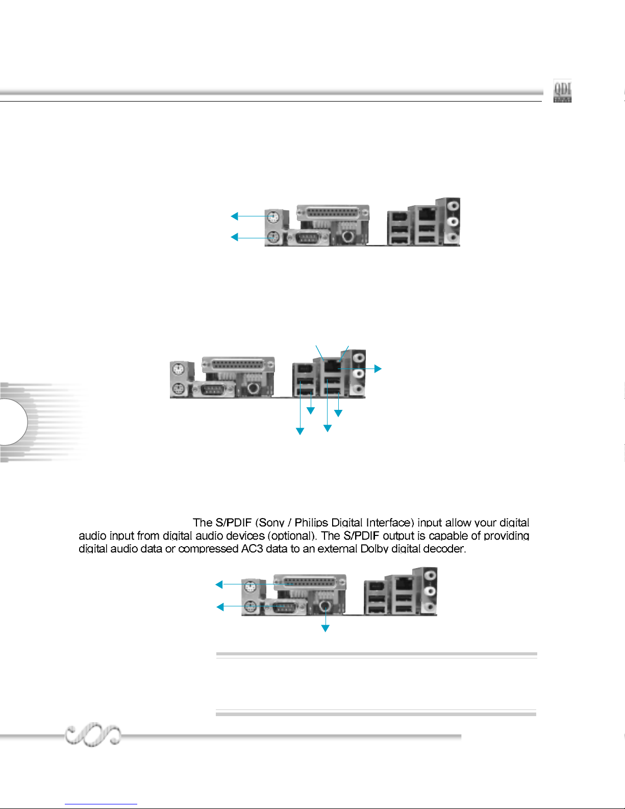
Parallel Port, Serial Port Connectors ( COM1 ) and SPDIF OUT Connector
The parallel port connector can be connected to a parallel device such as a printer. The serial
port COM1 connector can be connected to a serial port device such as a serial port mouse. You
can enable/disable them and choose the IRQ or I/O address in “Integrated Peripherals” from
AWARD BIOS SETUP.
Be sure to unplug the AC power supply before adding or removing expansion cards or other system peripherals, otherwise your
mainboard and expansion cards might be seriously damaged.
00
00
0
Warning:
USB1
USB2
LAN (optional)
LINK
ACTIVE
USB3
USB4
Parallel Port
COM1
SPDIF
7
P4I848PP4I848P
P4I848PP4I848P
P4I848P
Chapter 2Chapter 2
Chapter 2Chapter 2
Chapter 2
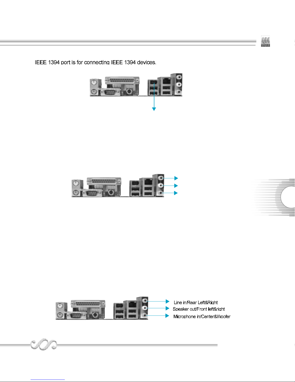
Line-in jack, Microphone-in jack and Speaker-out jack
The Line-in jack can be connected to devices such as a cassette or minidisc player to playback or
record.
The Microphone-in jack can be connected to a microphone for voice input.
The Speaker-out jack allows you to connect speakers or headphones for audio output from the
internal amplifier.
6-Channel Audio
(Available on -6A mainboard)
This mainboard utilizes ALC655 chip providing 6-channel Audio, which consists of Front Left, Front
Right, Rear Left, Rear Right, Center and Woofer for a complete surround sound effect. When 6Channel audio is available, the front Left&Right jack can be connected to the Front speskers, the
Back Left&Right jack can be connected to the rear speakers and the Center&Woofer jack can be
connected to the center speaker and woofer.
Microphone function is offered by F_AUDIO Connector on the mainboard now.
If set 2-Channel Audio mode on -6A mainboard, you can connect two speakers to the Front Left&Right
jack, at the same time use the Rear Left&Right jack as Line in jack, and use the Center&Woofer jack
as Microphone in jack.
1394 port(optional)
IEEE 1394 Port(optional)
Speaker Out
Line In
Microphone In
8
QDIQDI
QDIQDI
QDI
Installation InstrInstallation Instr
Installation InstrInstallation Instr
Installation Instr
uctionuction
uctionuction
uction
Hard Disk LED Connector (HD_LED)
The connector connects to the case’s IDE indicator LED indicating the activity status of IDE
hard disk. The connector has an orientation. If one way doesn’t work, try the other way.
Reset Switch (RESET)
The connector connects to the case’s reset switch. Press the switch once, the system
resets.
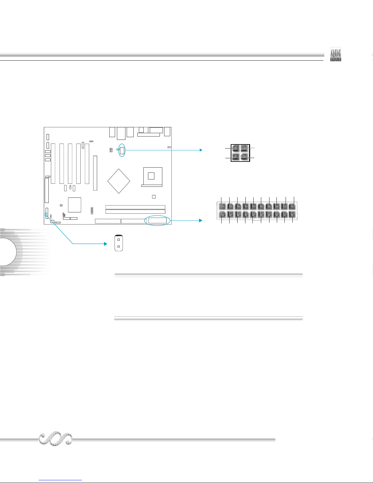
ATX 12V Power Supply Connector & Power Switch (POWER SW)
The power switch (POWER SW) should be connected to a momentary switch. When powering
up your system, first turn on the mechanical switch of the power supply (if one is provided),
then push once the power switch. When powering off the system, you needn’t turn off the
mechanical switch, just push once the power switch.
If you change “Soft-off by PWR-BTTN” from default “Instant-off”
to “Delay 4 Sec” in the “POWER MANAGEMENT SETUP” section of the BIOS, the power switch should be pressed for morethan
4 seconds before the system powers down.
Note:
POWER SW
1
ATX Power Supply Connector
20
1
12V
5VSB
5V
GND 3.3V GND 5V GND PS-OK 3.3V
5V5V
-5V GND PS-ON -12V 3.3V GND GND GND
12V
12V
GND
GND
+12V Power Supply Connector
1
9
P4I848PP4I848P
P4I848PP4I848P
P4I848P
Chapter 2Chapter 2
Chapter 2Chapter 2
Chapter 2
Speaker Connector (SPEAKER)
The connector can be connected to the speaker on the case.
Power LED Connector (PWR_LED)
When the system is in S0 status, the LED is on. When the system is in S1 status, the LED
is blink; When the system is in S3,S4, S5 status, the LED is off. The connector has an
orientation.
ACPI LED Connector (ACPI_LED)
The ACPI LED is a dual-color light with three pins. Pin1and Pin2 drive different color lights.
If Pin1 drives the orange light , then, Pin2 drives the green light, the following status will
come out. When the system is in S0 status, the LED is green on. When the system is in S1
status, the LED is green blink. When the system is in S3 status, the LED is orange on.
When the system is in S4, S5 status, the LED is off.
HDD_LED
SPEAKER
RESET
PWR_LED
ACPI_LED
POWER
SW
SPEAKER
RESET
ACPI_LED
PWR_LED
ORANGE(-)
GREEN(-)
LED+(VCC)
CUT
GND
LED+
LED-
GND
RESET
SPKDATA
NC
GND
VCC
POWER
SW
POWER
HDD LED(-)
HDD LED(+)
HDD LED
10
QDIQDI
QDIQDI
QDI
Installation InstrInstallation Instr
Installation InstrInstallation Instr
Installation Instr
uctionuction
uctionuction
uction
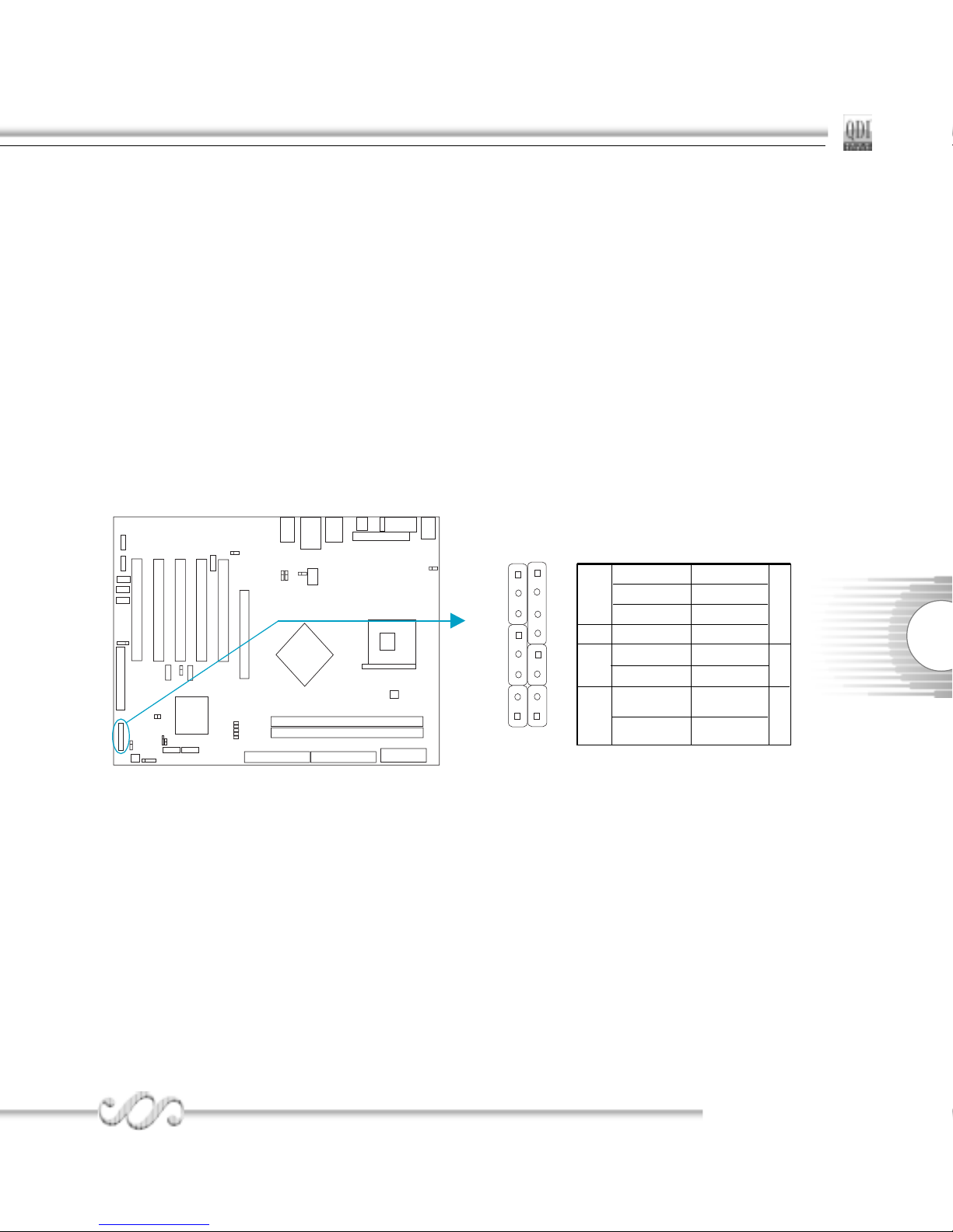
USB5,6; USB7,8
Besides USB1,2,3,4 on the back panel, P4I848P series of mainboards also have two 8-pin
headers on board which may connect to front panel USB cable( optional ) to provide additional
four USB ports.
Infrared Header (IrDA)
This connector supports wireless transmitting and receiving device. Before using this function, configure the settings for IR Address, IR Mode and IR IRQ from the “INTEGRATED
PERIPHERALS” section of the CMOS SETUP.
USB7,8
USB5,6
+5V
D7+
D7-
GND GND
N/A
+5V
D8-
D8+
CUT
+5V
D5+
D5-
GND GND
N/A
+5V
D6-
D6+
CUT
IrDA
VCC
IRRX
GND
IRTX
NC
11
P4I848PP4I848P
P4I848PP4I848P
P4I848P
Chapter 2Chapter 2
Chapter 2Chapter 2
Chapter 2
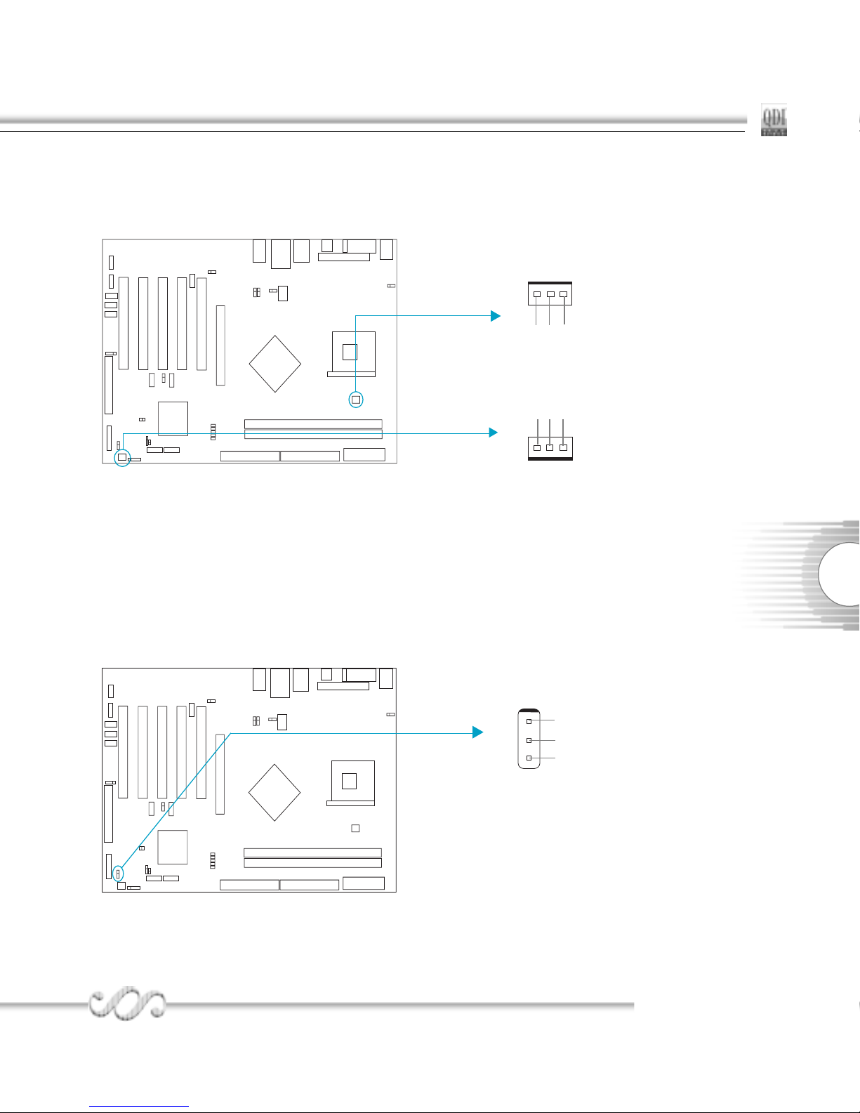
Wake-Up On Internal Modem (WOM)
Through this function, the system which is in the suspend or soft-off status can be waked up
by a ring signal received from the internal modem. When this function is used, be sure an
internal modem card which supports this function is used. Then connect this header to the
relevant connector on the modem card, set “Power on by Ring/LAN” as Enabled in the
“Power Management Setup” section of the CMOS SETUP. Save and exit, then boot the
operating system once to make sure this function takes effect.
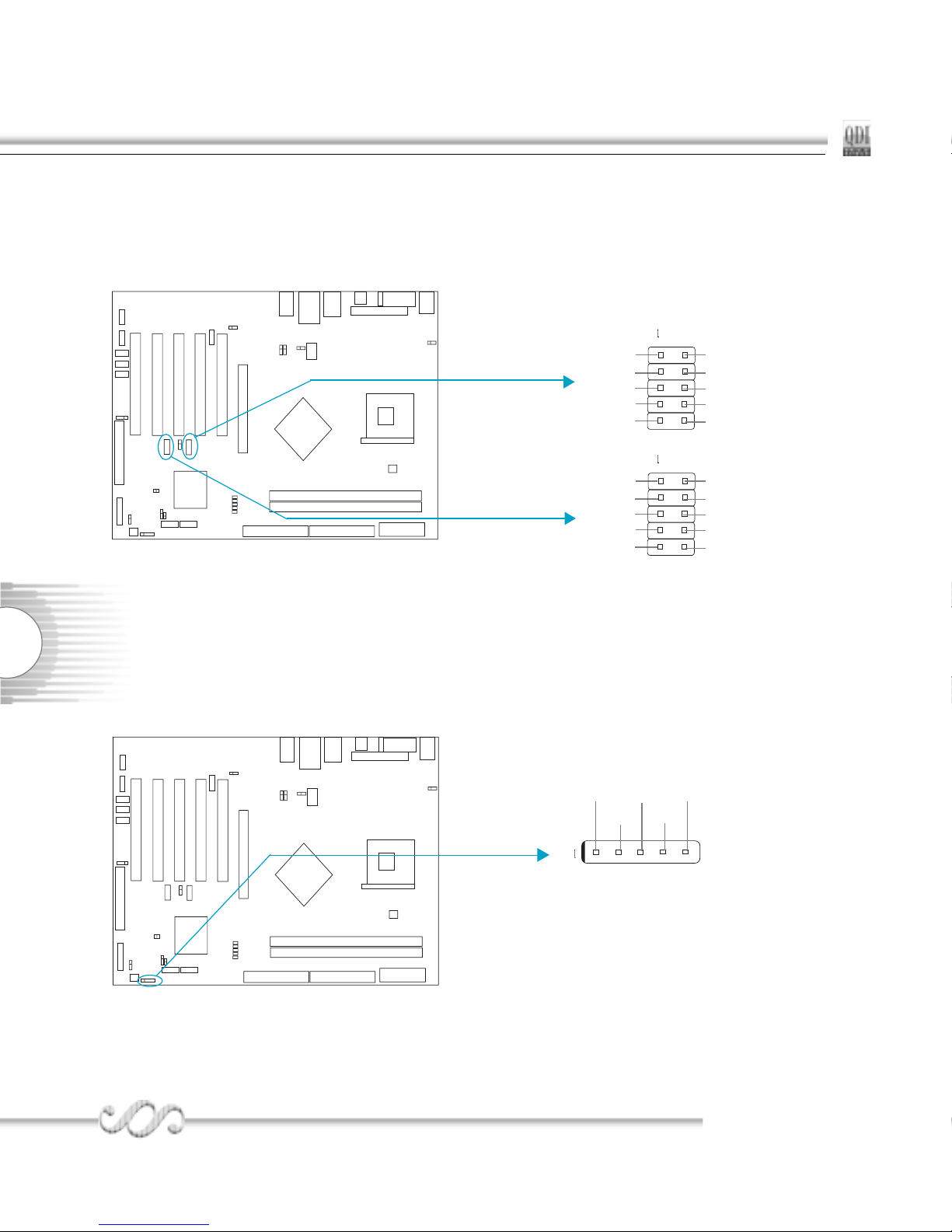
Fan Connectors (PWR_FAN, CPU_FAN)
The fan speed of these three fans can be detected and viewed in “PC Health” section of the
CMOS SETUP.
CPU_FAN
PWR_FAN
+12V
SENSE
GND
+12V
GND
SENSE
Signal for waking up(active low)
WOM
+5V standby
GND
1

12
QDIQDI
QDIQDI
QDI
Installation InstrInstallation Instr
Installation InstrInstallation Instr
Installation Instr
uctionuction
uctionuction
uction
Audio Connectors (CD_IN, AUX_IN, MODEM)
(Available on -6A mainboard)
4-pin SMBus Connector(SMBUS)
This connector allows you to connect SMBus devices. SMBus devices communicate through
the SMBus with a SMBus host and/or other SMBus devices. The SMBus or System Management Bus is a specific implementation of I
2
C bus, which is a multi-master bus, that is,
multiple devices can be connected to the same bus and each one can act as a master by
initiating data transfer.
MODEM
CD_IN
Phone-In (from Modem)
GND
Mono-Out (to Modem)
AUX_IN
CD Right Channel
GND
CD Left Channel
Left Audio Channel
GND
Right Audio Channel
SMBUS
SMBDATA
SMBCLD
5VSB
GND
13
P4I848PP4I848P
P4I848PP4I848P
P4I848P
Chapter 2Chapter 2
Chapter 2Chapter 2
Chapter 2
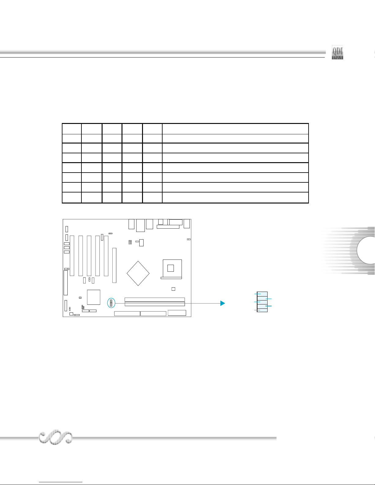
Diagnosis LED(Optional)
During the POST , the LED1~LED5 representing POST steps will light up in turn. During the
POST,If use the CPU of Hyper-Threading and Hyper-Threading is enable in the BIOS,the LEDs
will light up in turn, then blink together. please refer to the following table to learn the POST
status:
LED1 LED2 LED3 LED4 LED5 status
blink off off off off CPU damaged , BIOS chip absent or damaged
on off off off off system detect CPU and initialize chipset
off on off off off system detect memory
off off on off off system initialize PCI
off off off on off system initialize clockgen
off off off off on system detect Video and invoke Video BIOS
on on on on on Hyper-Threading OK
LED1
LED5
LED3
LED4
LED2
14
QDIQDI
QDIQDI
QDI
Installation InstrInstallation Instr
Installation InstrInstallation Instr
Installation Instr
uctionuction
uctionuction
uction
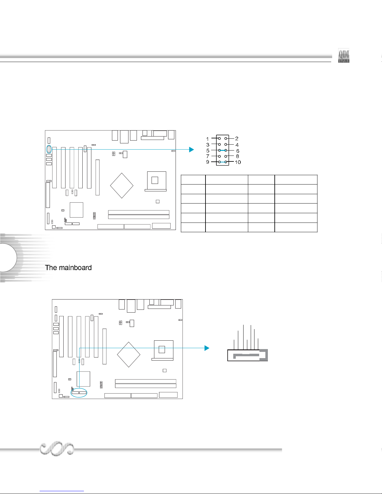
Front Audio Interface(F_Audio)
The audio interface provides two kinds of audio output choices: the FrontAudio, the
RearAudio. Their priority level is as sequence. When the FrontAudio is available, the
RearAudio will be cut off. An onboard amplifier is provided for the earphone. When the
FrontAudio is absent, Pin9 and Pin10, Pin5 and Pin6 must be short connected.
Onboard SATA
provides two Serial ATA connectors, SATA is a storage interface that is
compliant with SATA 1.0 Specification. With speed of up to 150Mbps. you can connect
Serial ATA cable to Serial ATA hard disk.
RX-
Pin No. Symbol Pin No. Symbol
1 AUD_MIC 2 AUD_GND
3 AUD_MIC_BIAS 4 ADU_VCC
5 AUD_FPOUT_R 6 AUD_RET_R
7 NC 8 (Cut away)
9 AUD_FPOUT_L 10 AUD_RET_L
F_AUDIO
SATA1/SATA2
GND
GND
GND
RX+
TX+
TX-
15
P4I848PP4I848P
P4I848PP4I848P
P4I848P
Chapter 2Chapter 2
Chapter 2Chapter 2
Chapter 2
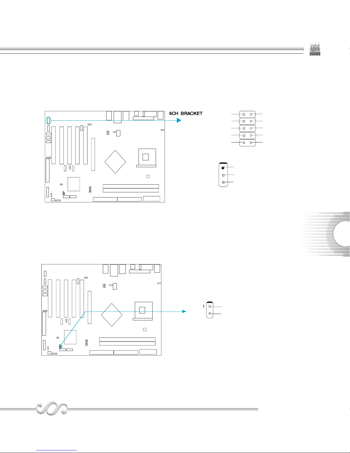
Chassis Security Switch (CHSSEC)
The connector connects to the chassis security switch on the case. The system can detect
the chassis intrusion through the status of this connector. If the connector has been closed
once, the system will record the status and indicate the chassis has been opened. You can
monitor or check this information from some software.
6CH-BRACKET Connector(optional)
The SPDIF input allow your digital audio input from digital audio devices.(optional) The
6CH_BRACKET output is capable of providing digital audio data or compressed AC3 data to
an external Dolby digital decoder.
SPDIF out
SPDIF in
GND
SPDIF
1
CENTER
SURR_R
SPDIF Input
SPDIF output
GND
VCC
SURR_L
CUTGND
BASS
CHSSEC
GND
Indicate signal
 Loading...