


Declaration of conformity
QUANTUM DESIGNS(HK) L TD.
5/F Somerset House, TaiKoo Place 979 Kings Road,
Quarry Bay, Hong Kong
declares that the product
Mainboard
KinetiZ 7T
is in conformity with
(reference to the specification under which conformity is declared in
accordance with 89/336 EEC-EMC Directive)
þ EN 55022 Limits and methods of measurements of radio disturbance
characteristics of information technology equipment
þ EN 50081-1 Generic emission standard Part 1:
Residential, commercial and light industry
þ EN 50082-1 Generic immunity standard Part 1:
Residential, commercial and light industry
European Representative:
QDI COMPUTER ( UK ) LTD QDI COMPUTER ( SCANDINAVIA ) A/S
QDI SYSTEM HANDEL GMBH QDI COMPUTER ( NETHERLANDS) B. V.
QDI COMPUTER (FRANCE) SARL QDI COMPUTER HANDELS GMBH
QDI COMPUTER (ESPANA) S.A. QDI COMPUTER (SWEDEN) AB
Signature : Place / Date : HONG KONG/2000
Printed Name : Anders Cheung Position/ Title : President

Declaration of conformity
Trade Name: QDI Computer ( U. S . A. ) Inc.
Model Name: KinetiZ 7T
Responsible Party: QDI Computer ( U. S. A.) Inc.
Address: 41456 Christy Street
Fremont, CA 94538
Telephone: (510) 668-4933
Facsimile: (510) 668-4966
Equipment Classification: FCC Class B Subassembly
Type of Product: Mainboard
Manufacturer: Quantum Designs (HK) Inc.
Address: 5/F, Somerset House, TaiKoo Place
979 Kings Road, Quarry Bay, HONG
KONG
Supplementary Information:
This device complies with Part 15 of the FCC Rules. Operation is subject to
the following two conditions : (1) this device may not cause harmful interference, and (2) this device must accept any interference received, including
interference that may cause undesired operation.
Signature : Date : 2000

CONTENTS
Facilité de vitesse Initialisation(Francais) ............................................. 1
1. Introduction................................................................. 3
Overview............................................................................................ 3
Key Features ...................................................................................... 3
Introduction to New Features .............................................................. 5
2. Installation Instructions .............................................. 7
External Connectors ................................................................. 7
PS/2 Keyboard & PS/2 Mouse Connector............................................. 7
USB1 & USB2...................................................................................... 7
USB3 & USB4...................................................................................... 7
Parallel Port Connector and Serial Port Connector ................................ 8
UART2 ..................................................................................................
Line-in jack(or Real out jack), Microphone-in jack, Speaker-out jack and
MIDI/Joystick connector ....................................................................... 8
ATX Power Supply Connector & Power Switch(POWER SW) .............. 8
Hard Disk LED Connector (HD LED) ..................................................... 9
Reset Switch (RESET)......................................................................... 9
Speaker Connector (SPEAKER)........................................................... 9
ACPI LED Connector (ACPI_LED) ......................................................... 9
GREEN LED Connector(GREEN_LED) .................................................. 9
Hardware Green Connector (SLEEP)................................................... 9
Power LED Connector(PWR_LED) ....................................................... 9
Key-lock connector(KEY_L) ..................................................................
Internal Audio Connectors(AUX,CDLIN, MODEM).................................11
Audio/Modem Riser Interface Connector(AMR) .................................. 12
Fan Connector (CPUFAN , CHSFAN, F AN3) ....................................... 10
Wake-Up On LAN (WOL)................................................................... 10
Wake-Up On Internal Modem (WOM)...................................................11
Infrared Header (IrDA)....................................................................... 12
Expansion Slots & I/O Ports description ............................................. 13
Jumper Settings ........................................................................... 13
Suspend to RAM Switch( J12) .......................................................... 13
I

CONTENTS
Clear CMOS(JCC) .................................................................................. 14
Enable/Disable onboard audio(JSD) ....................................................... 15
BIOS-ProtectEasy Jumper(JAV)............................................................. 14
Overclocking Jumper Setting (JFSB) ...................................................... 1 5
3. BIOS Description ..................................................................17
Utility Support .............................................................................. 17
AWDFLASH.EXE ................................................................................... 17
AW ARD BIOS Description........................................................... 18
Entering Setup .......................................................................................18
Load Fail-Safe Defaults ......................................................................... 18
Load Optimized Defaults........................................................................ 18
Standard CMOS Features Setup .......................................................... 18
Frequency/Voltage Control .................................................................... 32
Advance BIOS Features Setup ............................................................ 22
Advance Chipset Features Setup ........................................................ 24
Integrated Peripherals.......................................................................... 26
Power Management Setup................................................................... 28
PnP/PCI Configurations Setup .............................................................. 30
PC Health Status.................................................................................. 31
Set Supervisor/User Password ............................................................. 33
Boot with BIOS defaults ...................................................................... 33
Appendix A QDI Driver CD 2000 ............................................ 35
Appendix B Boot Logo .................................................... 37
RecoveryEasy....................................................................39
Introduction ........................................................................................... 39
Operation Process ................................................................................ 39
F AQ ...................................................................................................... 4 4
II

Caution
1. Be sure to add some Silicone Grease between the Socket A processor and FAN to keep them fully contact, meanwhile to meet the
heat sink requirement.
2. because the processor could overheat and damage both the processor and the motherboard, we recommend that you should have an AMD
authorized fan to prevent overheating.
3. The AC power status of the system is indicated by the red LED under
the three DIMM sockets. If the LED is on , adding or removing device like
SDRAM memory is porhibited.

KinetiZ 7A
Manual for KinetiZ 7T

Manual for KinetiZ 7T

-- This page is intentionally left blank --
Manual for KinetiZ 7T

Chapter 1
Chapter 1
Chapter 1
Introduction
Introduction
Overview
The KinetiZ 7T green mainboard utilizes the VIA Apollo KT-133 chipset, providing a costeffective PC/ATX platform with perfect capability and high performance to support Socket
®
A AMD
DuronTM/AthlonTM processors. The VIA® VT686A chipset integrates software
configurable AC’97 audio gives customers an advanced, multimedia solution at an extremely low price, also the KinetiZ K7T mainboard integrates Creative CT5880 PCI hardware
®
sound(Optional) to provide high quality 3D surrounding sound effect. The VIA
KT-133
chipset provide some new features such as AGP 4X mode and Ultra-Fast 200MHz FSB.
Equipped with three memory module sockets, 1.5GB PC66/100/133MHz SDRAM and PC100/
133 ECC or non-ECC SDRAM DIMMs can be supported. It also provides advanced features
such as wake-up on LAN and wake-up on internal/external modem function. Suspend to
RAM, the optimal implementation of the Advanced Configuration and Power Interface(ACPI)
specification, makes the PC’s power consumption drop to the lowest possible level and
enable quick wakeup. ManageEasy , our system management application is also supplied to
enable remote monitoring and configuration of the system.
Key Features
Form factor
l ATX form factor of 305mm x225mm.
Microprocessor
l Supports AMD Socket A Athlon
1GHz and further processors.
l Supports AMD Sokcet A Duron
processors.
l Supports 200MHz FSB
l On-board VDDQ(for AGP), 2.5V regulators and 3.3V switching power supply.
l Three channel power regulators for AMD Socket A Athlon
Chipset
l Apollo KT-133 chipset: VT8363, VT82C686A.
System memory
l Provides three 3.3V 168 pin DIMM sockets, supports 1.5G PC66/100/133 ECC or
non-ECC SDRAM DIMMS, VCM SDRAM.
l Minimum memory size is 8MB, maximum memory size is 1.5GB.
l SDRAM 64 bit data interface with ECC support.
On-board IDE
l Supports two PCI PIO and Bus Master IDE ports.
l Two fast IDE interfaces supporting four IDE devices including IDE hard disks and
CD-ROM drives.
TM
processors at 700/750/800/850/900/950MHz/
TM
processors at 600/650/700MHz and further
TM
/Duron
TM
Processors.
Manual for KinetiZ 7T

Introduction
l Supports “Ultra DMA/33”Synchronous DMA mode transferring up to 33 Mbytes/sec.
l Supports “Ultra DMA/66”Synchronous DMA mode transferring up to 66 Mbytes/sec.
l Integrated 16x32bit buffer for IDE PCI Burst Transfers.
On-chip I/O
l One floppy port supporting up to two 3.5
″
or 5.25″ floppy drives with
360K/720K/1.2M/1.44M/2.88M format.
l Two high speed 16550 fast compatible UART s(COM1/COM2/COM3/COM4
selective) with 16-byte send/receive FIFOs.
l One enabled parallel port at the I/O address 378H/278H/3BCH with additional
bi-direction I/O capability and multi-mode as SPP/EPP/ECP (IEEE 1284 compliant).
l Circuit protection provided, preventing damage to the parallel port when a
connected printer is powered up or operated at a high voltage.
l Supports LS-120 floppy disk drive and Zip drive.
l All I/O ports can be enabled/disabled in the BIOS setup.
On-chip Audio
l Build in VT82C686A
l Direct Sound AC97 Audio
l AC97 2.1 Compliant
®
*Creative
l PCI 2.2 compliant
l 3D audio effects.
l 32-voice XG wavetable synthesizer
l Direct Sound/Music Hardware Accelerator
l Full-Duplex stereo
l Supports four speakers output based on Speaker-out jack and Line-in jack.
CT5880 PCI Hardware Sound(Manufacturing Option)
AGP SLOT
l Supports 4X mode & AGP 2.0 compliant.
Advanced features
l PCI 2.2 Specification compliant.
l Supports 3.3V/5V PCI bus interface.
l Provides Trend ChipAwayVirus® On Guard and PC-Cillin software with killing virus
function.
l Provides four USB ports, on-board PS/2 mouse and PS/2 keyboard ports.
l Provides infrared interface.
l Support PC99 color- coding connector Specification.
l Supports Windows 98/Windwos 2000 software power-down.
l Supports wake-up on LAN and wake-up on internal/external modem.
l Supports auto fan off when the system enters suspend mode.
Manual for KinetiZ 7T

Chapter 1
l supports system monitoring (monitors system temperature, CPU temperature, voltages,
chassis intrusion and fan speed).
l Provides management application such as ManageEasy .
l Protects the system BIOS from being attacked by severe virus such as CIH, by
enabling “BIOS-ProtectEasy” in CMOS setup or closing the Jumper “JAV”.
BIOS
l Licensed advanced AWARD BIOS, supports flash ROM with 2M bit memory size,
plug and play ready.
l Supports IDE CD-ROM or SCSI boot up.
Green function
l Supports ACPI (Advanced Configuration and Power Interface) and ODPM (OS
Directed Power Management).
l Supports three green modes: Doze, Standby and Suspend.
l Supports ACPI power status: S0, S1, S3(STR), S5(Soft-off).
Expansion slots
l 1 ISA slot
l 5 PCI slots
l 1 AGP
l 1 AMR
Manual for KinetiZ 7T

Introduction
Introduction to New Features
BIOS-ProtectEasy
The BIOS of the mainboard is contained inside the Flash ROM. Severe viruses such as CIH
virus are so dangerous that it may overwrite the BIOS of the mainboard. If the BIOS has
been damaged, the system will be unable to boot. We provide the following solution which
protects the system BIOS from being attacked by such viruses.
There are two choices which can implement this function.
1. Set the jumper (JAV) as closed, the BIOS can not be overwritten.
2. Set the jumper (JAV) as open, meanwhile set “BIOS-ProtectEasy” as Enabled in AWARD
BIOS CMOS Setup. In this way , the BIOS can not be overwritten, but the DMI information
can be updated.
Refer to page 14 for detailed information on jumper setting, and page 22 for related BIOS
setting.
Ultra A T A/66
According to the previous A TA/IDE hard drive data transfer protocol, the signaling way to
send data was in synchronous strobe mode by using the rising edge of the strobe signal.
The Ultra A TA/33 protocol doubles the burst transfer rate from 16.6MB/s to 33.3MB/s, by
using both the rising and falling edges of the strobe signal, this time Ultra AT A/66 doubles
the Ultra AT A burst transfer rate once again (from 33.3MB/s to 66.6MB/s) by reducing setup
times and increasing the strobe rate. The faster strobe rate increases EMI, which cannot be
eliminated by the standard 40-pin cable used by ATA and Ultra ATA. To eliminate this
increase in EMI, a new 40-pin, 80-conductor cable is needed. This cable adds 40 additional
ground lines between each of the original 40 ground and signal lines. The additional 40 lines
help shield the signal from EMI, reduce crosstalk and improves signal integrity.
Ultra ATA/33 introduced CRC (Cyclical Redundancy Check), a new feature of IDE that
provides data integrity and reliability. Ultra A T A/66 uses the same process. The CRC value
is calculated by both the host and the hard drive. After the host-request data is sent, the
host sends its CRC to the hard drive, and the hard drive compares it to its own CRC value.
If the hard drive reports errors to the host, then the host retries the command containing
the CRC error.
Ultra ATA/66 technology increases both performance and date integrity . However there
are basically five requirements for your system to run in Ultra ATA/66 mode:
1. The system board must have a special Ultra AT A/66 detect circuit, such as
KinetiZ 7T mainboard.
2. The system BIOS must also support Ultra A T A/66.
3. The operating system must be capable of DMA transfers. Win95 (OSR2),
Win98 and WindowsNT are capable.
4. An Ultra ATA/66 capable, 40-pin, 80-conductor cable is required.
5. Ultra AT A/66 compatible IDE device such as a hard drive or CD-ROM drive.
Manual for KinetiZ 7T

Introduction Chapter 1
PC-133 Memory
PC133 SDRAM Unbuffered DIMM defines the electrical and mechanical requirements for
168-pin, 3.3 Volt, 133MHz, 64/72-bit wide, Unbuffered Synchronous DRAM Dual In-Line
Memory Modules (SDRAM DIMMs). Relatively , the peak bandwidth of PC-133 memory is
the 33% higher than PC-100 memory. These latest SDRAMs are necessary to meet the
enhanced 133MHz bus speed requirement.
Suspend to RAM
Suspend to RAM is a cost-effective, optimal implementation of the Advanced Configuration and Power Interface (ACPI) 1.0 specification, which makes a PC’s power consumption drop to the lowest possible level and enables quick wakeup. When the system is in
Suspend-to-RAM status, the system context is maintained in system memory, the system
consumes only a small fraction of the power used for full operation. Instead of shutting
down the system to save power when not in use and then having to reboot later, Suspend-to-RAM solution enables the system to quickly wake up, restoring all applications
and features, enabling operation in a few seconds.
To implement this function, the following requirments are essential:
1. Power supply requirements: The current of 5VSB line of the power supply should be
more than 0.75A.
2. Set the Jumper J13 with pin1&pin2 closed. Refer to page 13 for detailed information.
3. The BIOS option “ACPI function” should be enabled, and “ACPI Suspend Type” should
be set as S3 in AWARD BIOS CMOS setup. Refer to page 28 for detailed information.
4. An ACPI-enabled operating system such as Windows 98 or Windows 2000 family is
needed. Navigate to the CD-ROM drive from the MS-DOS Command Prompt and enter
the following from the Win98 directory on the CD:
D:\SETUP /P J
(This manual assumes that your CD-ROM device driver letter is D:)
Windows 98 will be installed with ACPI enabled.
For Windows 98 SE and Windows 2000, just install them directly.
5. Three ways to enter Suspend-to-RAM status under ACPI-enabled Windows 98:
l Click Start -> Shut down -> Standby to enable the system to enter Suspend-to-
RAM status.
l Click Start -> Setup -> Control Panel -> Power Management -> Advanced and
choose Standby item, the system will enter Suspend-to-RAM status when you
press power button.
l From Power Management Properties in Control Panel, set the latency time in
System Standby, the system will enter Suspend-to-RAM status when time out.
The same ways used to power up the system can be used to wake up the system from
Suspend-to-RAM status. For example, pushing the power button, through the Wake-onLAN, Wake-on-Modem function or RTC Alarm.
Manual for KinetiZ 7T
Introduction
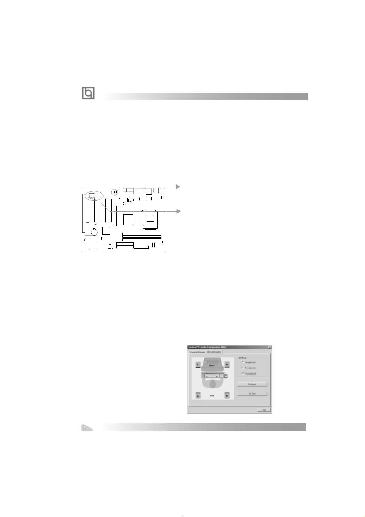
Creative CT5880 chipset
The CT5880 provides high-quality audio performance and low CPU utiliaztion for you.
Featuring 128-vioce wave-table synthesis with very high sample rate converters. In
addition, CT5880 supports localized three-dimensional sound immersion in headphone
and four-speaker environments. The four-speaker based on speaker-out and line-in jack.
the CT5880 also supports multiple algorithm levels of reverb and chorus effects on the
wave-table sounds as well as spatial sound enhancement on MIDI and wave sounds in
two speakers. Full duplex operation also allows simultaneous audio recording and playback.
The KinetiZ 7T mainboard has two solution for on-board sound.
Soft-sound(AC’97codec)
Hardware-sound(CT5880)(Option)
Note: If Creative® CT5880 chip is onboard, the slave card must be installed in
the first PCI slot.
Installation of CT5880 driver
Before you install CT5880 chipset driver, please make sure that CT5880 chipset is onboard.
1. If CT5880 chipset is onboard, the CD2000 will detected it and the option “ PCI Sound
Driver” will appear on screen, you click this option to install CT5880 chipset driver .
2. If CT5880 is not onboard, the CD 2000 will detected AC97codec and the option “ Audio
Codec Driver” will appear on screen, you click this option to complete the installation
Note : After installation of CT5880dirver, you
can select four speaker output function
Manual for KinetiZ 7T
chapter 2
Chapter 2
Chapter 2
Installation Instructions
Installation Instructions
This section covers External Connectors and Jumper Settings. Refer to the mainboard
layout chart for locations of all jumpers, external connectors, slots and I/O ports. Furthermore, this section lists all necessary connector pin assignments for your reference. The
particular state of the jumpers, connectors and ports are illustrated in the following figures.
Before setting the jumpers or inserting these connectors, please pay attention to the directions.
Be sure to unplug the AC power supply before adding or removing expansion
cards or other system peripherals, otherwise your mainboard and expansion
cards might be seriously damaged.
External Connectors
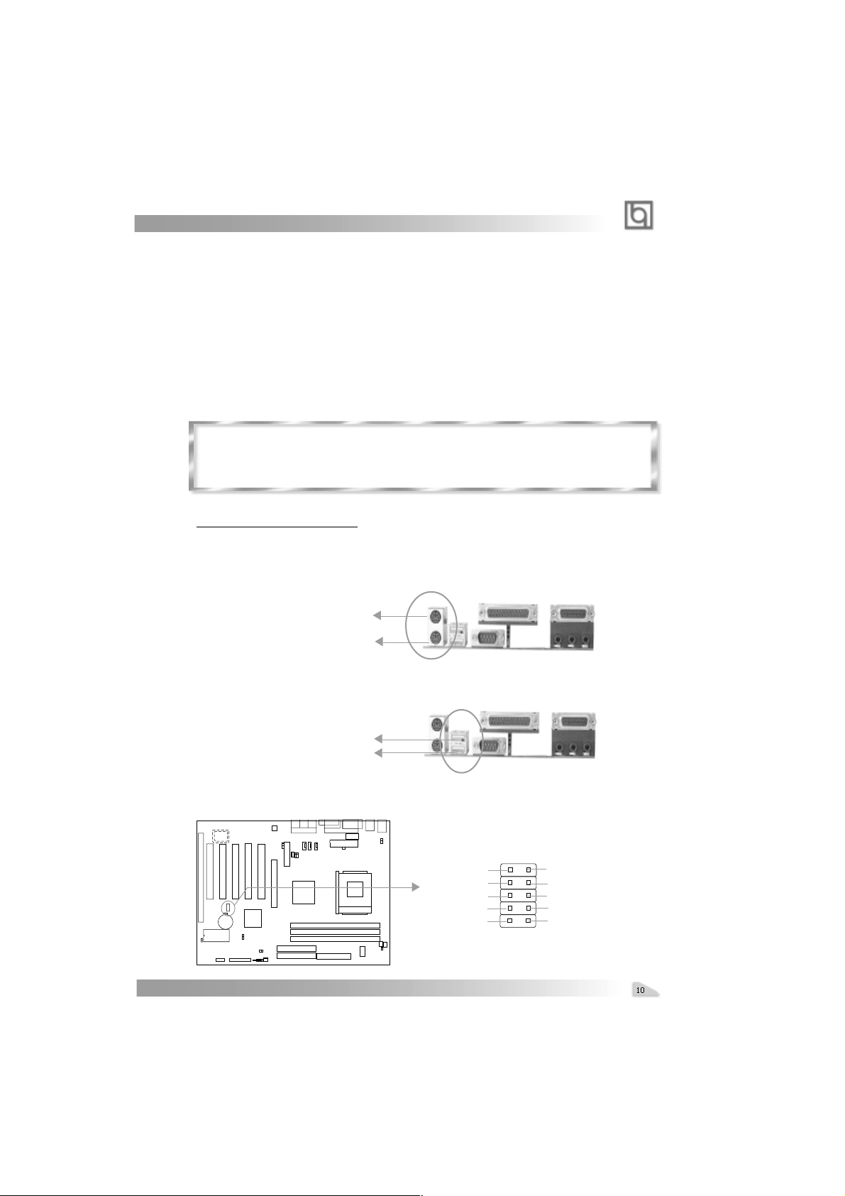
PS/2 Keyboard Connector, PS/2 Mouse Connector
PS/2 keyboard connector is for the usage of PS/2 keyboard. If using a standard AT size
keyboard, an adapter should be used to fit this connector. PS/2 mouse connector is for the
usage of PS/2 mouse.
PS/2 Mouse Connector
PS/2 Keyboard Connector
USB1, USB2
Two USB ports are available for connecting USB devices.
USB1
USB2
USB3, USB4
Two USB ports are not available on the back panel. Therefore, we provide a 10-pin ribbon
cable with bracket to connect Built-in on-board USB header. ( manufacturing option)
+5v
T1T1+
GND
GND
Manual for KinetiZ 7T
GND
GND
T0+
T0+5v
Installation Instruction
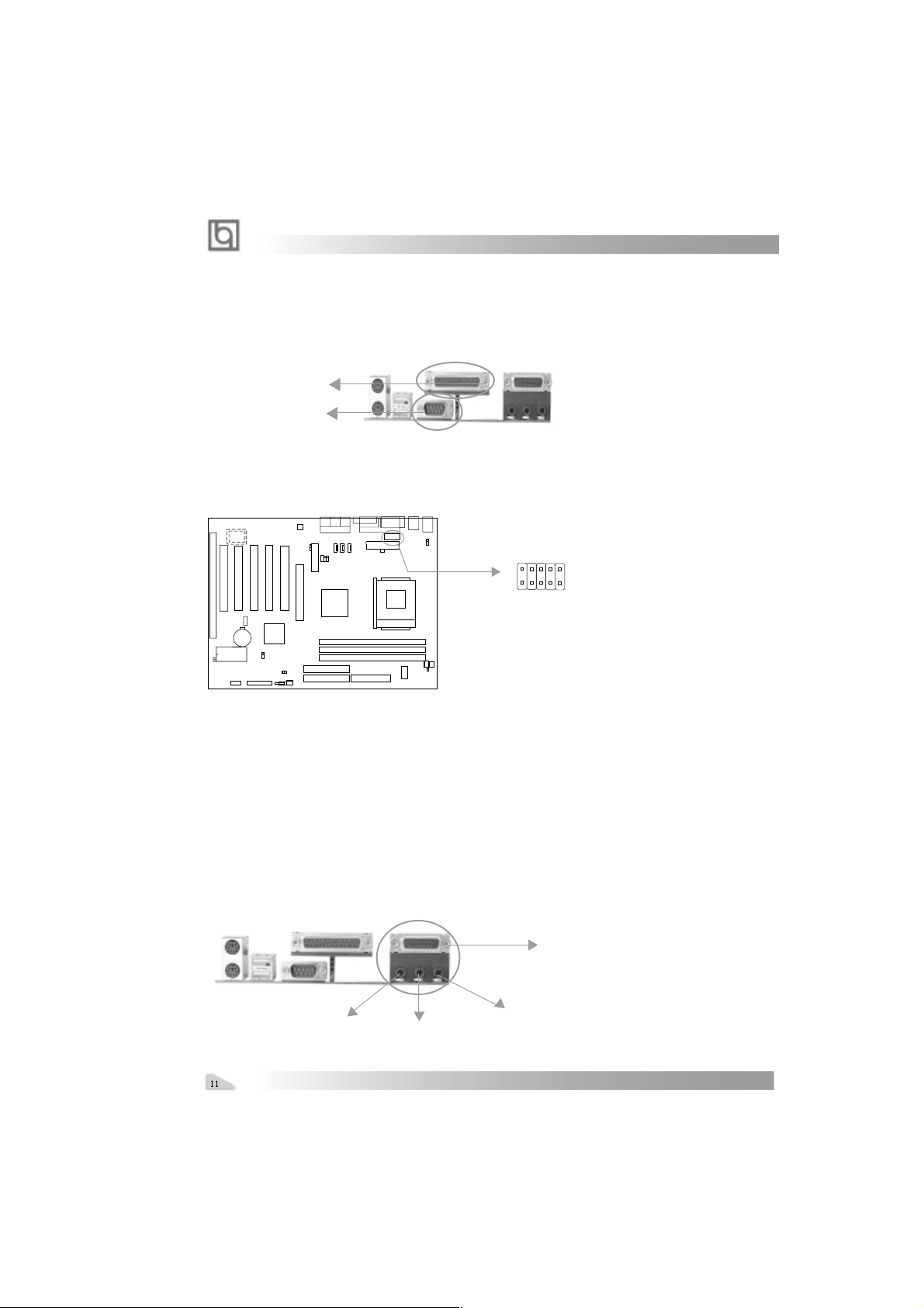
Parallel Port Connector and Serial Port Connector (UART1)
The parallel port connector can be connected to a parallel device such as a printer, while
the serial port connector can be connected to a serial port device such as a serial port
mouse. You can enable/disable them and choose the IRQ or I/O address in “Integrated
Peripherals” from AW ARD BIOS SETUP .
Parallel Port
UART1
UART2
The serial port UART2 is not available on the back panel. Therefore, we provide a 9-pin
ribbon cable with bracket for UART2 port. (manufacturing option)
1
UART2
Line-in jack(or Rear out jack), Microphone-in jack, Speaker-out jack
and
MIDI/Joystick connector
The Line-in jack can be connected to devices such as a cassette or minidisc player for
playback or recording. The Microphone-in jack can be connected to a microphone for voice
input. The Speaker-out jack allows you to connect speakers or headphones for audio
output from the internal amplifier .
Note: if you choose four speaker output in CT5880 configuration, the Rear out
jack replaces Line-in jack to connects powered speakers for audio output.
The MIDI/Joystick connector allows you to connect a game joystick or a MIDI device.
MIDI/Joystick
Speaker out
Line in(or Rear out ) jact
Manual for KinetiZ 7T
Microphone in
chapter 2
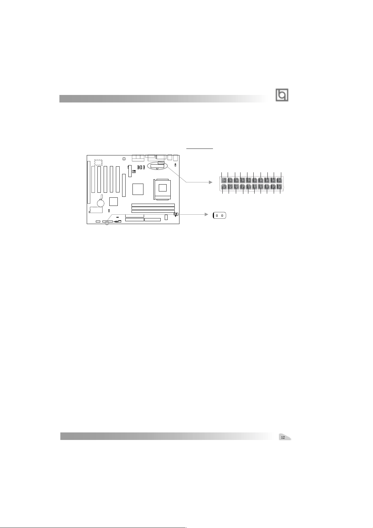
ATX Power Supply Connector & Power Switch (POWER SW)
Be sure to connect the power supply plug to this connector in its proper orientation. The
power switch (POWER SW) should be connected to a momentary switch (power button).
When powering up your system, first turn on the mechanical switch of the power supply (if
one is provided), then push once the power button. When powering off the system, you
needn’t turn off the mechanical switch, just
Push once* the power button.
ATX Power Supply Connector
3.3V 3.3V GND 5V GND 5V GND PS-OK 5VSB 12V
1
3.3V -12V GND PSON GND GND GND -5V 5V 5V
POWER
SW
Note: * If you change “soft-off by PWR-BTTN” from default “Instant-off” to “Delay
4 Secs” in the “POWER MANAGEMENT SETUP” section of the BIOS, the power
button should be pressed for more than 4 seconds before the system powers
down.
Hard Disk LED Connector (HD LED)
The connector connects to the case’s IDE indicator LED indicating the activity status of IDE
hard disk. The connector has an orientation. If one way doesn’t work, try the other way.
20
Reset Switch (RESET)
The connector connects to the case’s reset switch. Press the switch once, the system
resets.
Speaker Connector (SPEAKER)
The connector can be connected to the speaker on the case.
ACPI LED Connector (ACPI_LED)(Reserved)
The ACPI LED is double-color lights with three pins. Pin1&Pin2 drive different color lights. If
Pin1 drives the yellow light , Pin2 drives the green light, the following status will come out.
When the system is in power up status, the LED is green on. When the system is in suspend
status, the LED is green blink. When the system is in suspend to RAM status, the LED is
orange on. When the system is in soft-off status, the LED is off.
GREEN LED Connector (GREEN_LED)
The GREEN LED has five status. When the system is in three status (including power up,
suspend, soft-off), the LED is off. When the system is in suspend to RAM status, the LED
is on. When the system is in APM(advanced power management), the LED is on.
Hardware Green Connector (SLEEP)
Push once the switch connected to this header, the system enters suspend mode.
Manual for KinetiZ 7T

Installation Instruction
Power LED Connector (PWRLED)
The power LED has four status. When the system is in power up status, the LED is on.
When the system is in suspend status, the LED is blink. When the system is in Suspend to
RAM, the LED is off. When the system is in Soft-Off status, the LED is off.The connector has
an orientation.
Key-Lock Connector(KEY_L)
The connector can be connected to the keyboard lock switch on the case for locking the
keyboard.
HDLED
HDDLED
HDDLED
SPEAKER
ACPI_LED
SPEAKER
GND
VCC
NC
RESET
Power
SW
SPKDATA
RESET
RE-
GREEN_LED
SLEEP
EMPTY
GND
POWER_LED
Green_LED
LED
LED
LED
KEY_L
KEY_L
GND
KEYLOCK
HDDLED +
LED2 -
LED1 -
ACPI
LED
POWER
LED+(VCC)
GND
Power
EMPTY
EMPTY
SLEEP
SLEEP
GND
LED -
LED
POWER
LED
LED -
Fan Connector (CPUFAN, CHSF AN. F AN3)
These connectors support cooling fans of 35ma or less. Besides speed of the FAN3, The
speeds of the CPU fan and chassis fan can be detected and viewed in “PC Health Status”
section of the BIOS, . They will be automatically turned off after the system enters suspend
mode.
FNA3
FAN GND
+12V
SENSE
CPUFAN
FAN GND
+12V
SENSE
+12V
FAN GND
CHSF A N
SENSE
Manual for KinetiZ 7T

chapter 2
Internal Audio Connectors (AUX, CDLIN, MODEM)
AUX and CDLIN connectors allow you to receive stereo audio input from such sound
sources as a CD-ROM, TV tuner, or MPEG card. The MODEM connector allows the onboard
audio to interface with a voice modem card with a similar connector. It also allows the
sharing of mono_in (such as a phone) and mono_out (such as a speaker) between the
onboard audio and the voice modem card.
CDLIN
CD Right Channel
Mono-Out (to Modem)
Right Audio Channel
CD Left Channel
Common
MODEM
Phone-In (from Modem)
GND
AUX
Left Audio Channel
GND
Audio/Modem Riser Interface Connector (AMR)
The AMR Interface Connector is the interface between the mainboard and the Audio/Modem
Riser card. The connector provides all necessary signals which supports several different
configurations of audio and modem in the system, such as audio and modem on the Riser,
audio on the mainboard and modem on the Riser, or no audio with modem on the Riser.
KinetiZ 7A mainboard provides you with audio onboard solution, onboard audio can be
enabled/disabled. Either AMR (Audio/Modem Riser) card or MR (Modem Riser) card can be
used on this system. This software configurable AC’97 audio and modem system gives
customers an advanced, multimedia solution at an extremely low price. The AC’97 audio and
modem system can be enabled/disabled in “Integrated Peripherals” in AWARD BIOS CMOS
Setup.
Manual for KinetiZ 7T
AMR Interface Connector

Installation Instruction
Wake-Up On Internal Modem (WOM)
Through the Wake-Up On Internal Modem function, the system which is in the power-off
status can be powered on by a ring signal received from the internal modem. If this function
is to be used, be sure an internal modem card which supports the function is used. Then
connect this header to the relevant connector on the modem card, set “Wake Up On LAN/
Ring ” as Enabled in the “POWER MANAGEMENT SETUP” section of the BIOS. Save & exit,
then boot the operating system once to make sure this function takes effect.
Signal for waking up (active low)
+5V standby
GND
1
Wake-Up On LAN (WOL)
Through the Wake-Up On LAN function, a wake event occurring from the network can
wake up the system. If this function is to be used, please be sure an ATX 2.01 power
supply of which 5VSB line is capable of delivering 720mA, and a LAN adapter which
supports this function are used. Then connect this header to the relevant connector on the
LAN adapter , set “PowerOn by Ring/LAN” as Enabled in the “POWER MANAGEMENT SETUP”
section of the BIOS. Save & exit, then boot the operating system once to make sure this
function takes effect.
Signal for waking up (active high)
GND
+5V standby
1
Infrared Header (IrDA)
This connector supports wireless transmitting and receiving. If using this function, set
“UART 2 Mode” to HPSIR or ASKIR and configure the settings from the “INTEGRATED
PERIPHERALS” section of the BIOS.
Manual for KinetiZ 7T
VCC
NC
IRRX
GND
IRTX
VCC

chapter 2
Expansion Slots & I/O Ports description
Slot / Port Description
PCI 1 First PCI slot.
PCI 2 Second PCI slot.
PCI 3 Third PCI slot.
PCI 4 Fourth PCI slot.
PCI 5 Fifth PCI slot.
DIMM1 First DIMM slot.
DIMM2 Second DIMM slot.
DIMM3 Third DIMM slot.
IDE 1 Primary IDE port.
IDE 2 Secondary IDE port.
AMR AMR slot.
AGP AGP slot.
FLOPPY Floppy Drive Port.
Jumper Settings
Jumpers are located on the mainboard. Pin 1 for all jumpers are located on the side with a
thick white line ( Pin1→ ), refer to the mainboard’s silkscreen . Jumpers with three
pins will be shown as to represent pin1 & pin2 connected and to represent
pin2 & pin3 connected.
Suspend to RAM Switch (J12)
If you want to Disable Suspend to RAM function, set J13 with pin2&pin3 closed, meanwhile,
set “ACPI Suspend Type” to S1 in “Power Management Setup” section of the BIOS. Otherwise, set J13 with pin1&pin2 closed for implementing this function.
Warning: If you set J13 with pin2&pin3 closed and set “ACPI Suspend Type” to S3 in
“Power Management Setup” section of the BIOS, the
in this case, just clear CMOS and boot up the system once again.
Disable STR
Enable STR
Manual for KinetiZ 7T
blank screen will come out,
1
J12
1
J12

Installation Instruction
Enable/Disable on-board audio(JSD)
If you want to use the on-board audio, set JSD with pin2 & pin3 closed (default).
Otherwise, set JSD with pin1 & pin2 closed for disabling this function.
Enable on-board audio:
Disable on-board audio:
1
JSD
1
JSD
Clear CMOS (JCC)
If you want to clear CMOS, unplug the AC power supply first, close JCC (pin1 & pin2) once,
set JCC back to the normal status with pin2 & pin3 connected, then power on the system.
Normal status:
Clear CMOS:
(Unplug the AC power supply)
1
JCC
1
JCC
BIOS-ProtectEasy Jumper (JA V)
The BIOS of the mainboard is contained inside the Flash ROM. If the jumper JA V is set as
closed, you will be unable to flash the BIOS to the mainboard. However in this status, the
system BIOS is protected from being attacked by serious virus such as CIH virus.
Flash Write Enabled
Flash Write Disabled
Manual for KinetiZ 7T
JAV
JAV

chapter 2
Setting the jumper JA V as open(default), meanwhile disabling the “BIOS_ProtectEasy” item
from “Advanced BIOS Features” in AWARD BIOS CMOS Setup, allows you to flash the
BIOS to the Flash ROM.
The DMI (Desktop Management Interface) system information such as the CPU type/speed,
memory size, and expansion cards will be detected by the onboard BIOS and stored in the
flash ROM. Whenever the system hardware configuration is changed, DMI information will
be updated automatically. However , setting jumper JA V as closed makes flashing BIOS and
updating DMI information impossible. Therefore, set JAV as closed when changing the
system hardware configuration, or the error message “Unkown Flash Type” will be displayed on the screen, and DMI information update will be fail.
Overclocking Jumper Setting (JFSB)
Jumpers labeled JFSB is located on the mainboard providing users with CPU overclocking
feature. The host bus speed can be set as 100/133MHz. Refer to the chart below for the
location of these jumpers, and the table for information on how to set them.
JFSB
1
JFSB
1
HCLK
100
133
AMD Athlon
JFSB
CLOSE
OPEN
TM
CPU FSB is 100MHz, but delivering twice the throughput of 100MHz Pentium IIIbased systems( Ultra -Fast 200MHz ). So setting up to 133MHz FSB is also supported.
However, whether or not your system can be overclocked depends on your processor’s
capability. Whether the processor is bus ratio locked or unlocked should also be taken into
account. We do not guarantee the overclocking system to be stable.
Manual for KinetiZ 7T

-- This page is intentionally left blank --
Manual for KinetiZ 7T

Chapter 3
Chapter 3
Chapter 3
BIOS Description
BIOS Description
Utility Support:
AWDFLASH.EXE
This is a flash memory write/read utility used for the purpose of upgrading your BIOS
when necessary. Before doing so, please note:
l We strongly recommend you only upgrade BIOS when encounter problems.
l Before upgrading your BIOS, review the description below to avoid making
mistakes, destroying the BIOS and resulting in a non-working system.
When you encounter problems, for example, you find your system does not support the
latest CPU released on our current mainboard, you may therefore upgrade the BIOS,
please don’t forget to set JAV as open and disable the “Flash Write Protect” item in
AWARD BIOS CMOS Setup first .
Follow the steps exactly for a successful upgrade.
1. Create a bootable system floppy diskette by typing Format A:/s from the DOS
prompt under DOS6.xx or Windows 9x environment.
2. Click “Browse CD” option under QDI Driver CD 2000, copy Awdflash.exe (version>7.36)
from the directory \Utility onto your new bootable diskette.
3. Download the updated BIOS file from the Website (http://www.qdigrp.com). Please
be sure to download the suitable BIOS file for your mainboard.
4. Decompress the file downloaded, copy the BIOS file (xx.bin) onto the bootable
diskette, and note the checksum of this BIOS which is located in readme file.
5. Reboot the system from the bootable diskette created.
6. Then run the Awdflash utility at the A:\ prompt as shown below:
A:\Awdflash xxxx.bin
Follow the instruction through the process. Don’t turn off power or reset the
system until the BIOS upgrade has been completed.
If you require more detailed information concerning Awdflash Utility, for example, the
different usage of parameters, please type A:\>Awdflash /?
Note: There’s a shortcut to update your BIOS by pressing “Alt+F2“ in POST and inserting
the floppy which contains the updated file. The system will automatically update it.
Manual for KinetiZ 7T

BIOS Description
AWARD BIOS Description
Entering Setup
Power on the computer, when the following message briefly appears at the bottom of
the screen during the POST (Power On Self Test), press <Del> key or simultaneously
press the <Ctrl> + <Alt> + <Esc> keys, to enter the AW ARD BIOS CMOS Setup Utility .
Press <Del> to enter SETUP
Once you have entered, the Main Menu (Figure 1) appears on the screen. The main menu
allows you to select from twelve setup functions and two exit choices. Use the arrow
keys to select among the items and press the <Enter> key to accept or enter the submenu.
Figure-1 Main Menu
Load Fail-Safe Defaults
The Fail-Safe Defaults are secure and useful for system. It is recommended that users
load the Fail -Safe Defaults when the system is in trouble.
Load Optimized Defaults
The Optimized Defaults are common and efficient. It is recommended that users load
the optimized defaults first, then modify the needed configuration settings.
Standard CMOS Features Setup
The basic CMOS settings included in “Standard CMOS Features” are Date, Time, Hard
Disk Drive Types, Floppy Disk Drive T ypes, and VGA etc. Use the arrow keys to highlight
the item, then use the <PgUp> or <PgDn> keys to select the value desired in each item.
Manual for KinetiZ 7T

Chapter 3
Figure-2 Standard CMOS Setup Menu
For the items marked, press enter, a window will pop up as shown below. Y ou can view
detailed information or make modifications.
Figure-2-1 IDE Primary Master Setup Menu
Hard Disk
Primary Master/Primary Slave/Secondary Master/Secondary Slave
These categories identify the HDD types of 2 IDE channels installed in the computer system.
There are three choices provided for the Enhanced IDE BIOS: None, Auto, and User. ‘None’
means no HDD is installed or set; ‘Auto’ means the system can auto-detect the hard disk when
booting up; by choosing ‘user’, the related information should be entered regarding the follow-
ing items. Enter the information directly from the keyboard and press < Enter>:
CYLS number of cylinders HEAD number of heads
PRECOMP write pre-compensation LANDZ landing zone
SECTOR number of sectors MODE HDD access mode
Manual for KinetiZ 7T

BIOS Description
The Award BIOS supports 3 HDD modes: NORMAL, LBA and LARGE.
NORMAL
Generic access mode in which neither the BIOS nor the IDE controller will make any transformation during accessing. The maximum number of cylinders, heads and sectors for
NORMAL mode are 1024,16 and 63.
If the user sets his HDD to NORMAL mode, the maximum accessible HDD size will be 528
megabytes even though its physical size may be greater than that.
LBA (Logical Block Addressing) mode
A new HDD accessing method to overcome the 528 Megabyte bottleneck. The number of
cylinders, heads and sectors shown in setup may not be the number physically contained
in the HDD.
During HDD accessing, the IDE controller will transform the logical address described by
sector, head and cylinder number into its own physical address inside the HDD.
LARGE mode
Some IDE HDDs contain more than 1024 cylinder without LBA support (in some cases,
users do not want LBA). The Award BIOS provides another alternative to support these
kinds of HDD.
BIOS tricks DOS (or other OS) into divising the number of cylinders is less than 1024 by dividing
it by 2. At the same time, the number of heads is multiplied by 2. A reverse transformation
process will be made inside INT13h in order to access the right HDD address.
If using Auto detect, the BIOS will automatically detect the IDE hard disk mode and set it as
one of the three modes.
Remark
To support LBA or LARGE mode of HDDs, there must be some softwares involved which
are located in Award HDD Service Routine(INT13h).It may fail to access a HDD with LBA
(LARGE) mode selected if you are running under an Operating System which replaces the
whole INT 13h.
Manual for KinetiZ 7T

Chapter 3
Video
Set this field to the type of video display card installed in your system.
EGA/ VGA Enhanced Graphics Adapter / Video Graphic Array. For EGA,
VGA, SEGA, SVGA, or PGA monitor adapters.
CGA 40 Color Graphic Adapter, powering up in 40 column mode.
CGA 80 Color Graphic Adapter, powering up in 80 column mode.
MONO Monochrome adapter, including high resolution monochrome
adapters.
Halt On
This category determines whether or not the computer will stop if an error is detected
during powering up.
No errors The system boot will not stop for any errors that may be
detected.
All errors Whenever the BIOS detects a non-fatal error, the system will
stop and you will be prompted.
All, But Keyboard The system boot will not stop for a keyboard error; but it will
stop for all other errors.
All, But Diskette The system boot will not stop for a disk error; but it will stop
for all other errors.
All, But Disk/Key The system boot will not stop for a keyboard or disk error, but it will
stop for all other errors.
Memory
This is a Display-Only Category, determined by POST (Power On Self Test) of the BIOS.
Base Memory The POST of the BIOS will determine the amount of base
(or conventional) memory installed in the system.
Extended Memory The BIOS determines how much extended memory is
presented during the POST.
Total Memory Total memory of the system equals the sum of the above
memory.
Manual for KinetiZ 7T

BIOS Description
Frequency/Voltage Control
Figure-9 Frequency/Voltage Control Menu
The following indicates the options for each item and describes their meaning.
Item Option Description
l Auto Detect DIMM/ Enabled Closes the CLK signal if no PCI or DIMM
PCI Clk Disabled plug in.
l CPU Host/PCI/ Default These items are of selected CPU FSB
spread spec. 100/33Mhz/-0.5% and PCI clock.Default setting is recom-
100/33Mhz/ 0.25% mended.
100/33Mhz/ 0.5% 0.5%, 0.25%,-0.5% means enable
102/34Mhz/off clock Spread Spectrum to reduce EMI
...... 0.5%, 0.25%,-0.5%.
133/33Mhz/-0.5% Off means disable clock spreadspecturm
133/33Mhz/ 0.25% to reduce EMI.
100/33Mhz/ 0.5%
Manual for KinetiZ 7T

Chapter 3
Advanced BIOS Features Setup
Figure-3 Advanced BIOS Features Setup Menu
The following indicates the options for each item and describes their meaning.
Item Option Description
l Anti-Virus Enabled Allows you to choose the VIRUS warning feature
Protection for IDE Hard Disk boot sector protection. If this
function is enabled and someone attempt to write
data into this area, BIOS will show a warning
message on screen and alarm beep.
Disabled Invalidates this function.
l CPU Enabled Enables CPU internal Level1/Level2 cache.
Internal Cache Disabled Disables CPU internal Level1/Level2 cache.
l External Cache Enabled Enables external L2 cache. this allows better
performance.
Disabled Disable external cache.
l CPU L2 Cache Enabled Enables CPU L2 Cache ECC function.
ECC Checking Disabled Disables CPU L2 Cache ECC function.
l Quick Power Enabled Enables quick POST . BIOS will shorten or skip some
On Self Test check items during POST to speed up POST after
you power on the computer.
Disabled Normal POST .
l First (Second, Disabled Selects your Boot Device Priority. It could be
Third) Boot Device Floppy Disabled, Floppy , LS/ZIP, HDD-0, HDD-1, HDD-2,
Boot other Device HDD-3, SCSI, CDROM, LAN.
l Swap Floppy Enabled Exchanges the assignment of A&B floppy drives.
Drive Disabled The assignment of A&B floppy drives are normal.
Manual for KinetiZ 7T

BIOS Description
l Boot Up Enabled Tests floppy drives to determine whether they
Floppy Seek Disabled have 40 or 80 tracks.
l Boot Up On Keypad is used as number keys.
Numlock Status Off Keypad is used as arrow keys.
l Gate A20 Normal The A20 signal is controlled by the keyboard controller
Option or chipset hardware.
Fast Default setting. The A20 signal is controlled by Port 92
or the chipset specific method.
l Typematic Rate Enabled Keystrokes repeat at a rate determined by the
Setting Disabled keyboard controller - when enabled, the
typematic rate and typematic delay can be
selected.
l Typematic Rate 6-30 The rate at which character repeats when you
(Chars/Sec) hold down a key.
l T ypermatic Delay 250-1000 The delay before keystrokes begin to repeat.
(Msec)
l Security Option System Selects whether the password is required every
Setup time the system boots or only when you enter
setup.
l OS Select For Non-OS2 If your operating system is not OS/2, please select
DRAM>64MB this item.
OS2 If system DRAM is more than 64MB and the operating
system is OS/2, please select this item.
l Video BIOS Enabled Video BIOS will be copied to RAM. Video Shadow
Shadow will increase the video speed.
Disabled Video shadow is disabled.
l C8000~CBFFF Enabled Optional ROM will be copied to RAM by 16K bytes
Shadow: per unit.
... ...
DC000-DFFFF
Shadow: Disabled The shadow function is disabled.
l Flash Write Enabled Does not allow you to upgrade the BIOS.
Protect Note: Enabling this item can protect the
system BIOS from being attacked by severe
virus such as CIH. Therefore disable this
item item only when wanting to flash BIOS,
afterwards set this item as Enabled (default).
Disabled Disabling this item allows you to upgrade the BIOS.
l Show Bootup Enabled Enables the logo when system boots up.
Logo Disabled Logo will not be shown when system boots up.
Manual for KinetiZ 7T

Chapter 3
Advanced Chipset Features Setup
Figure-4 Advanced Chipset Features Setup Menu
The following indicates the options for each item and describes their meaning.
Item Option Description
l Bank 0/1, 2/3, 4/5 SDRAM 8/10ns These items are of selected SDRAM read/write
DRAM Timing Normal timing. Ensure your DIMMs are as fast as 8ns,
Medium otherwise select 10ns. The faster you choose,
Fast the higher performance you can receive.
Turbo
l SDRAM Cycle Auto/2/3 Defines the CLT timing parameter of SDRAM
Length expressed in 66MHz clocks.
Latency Time = Auto, according to SDRAM SPD.
Latency Time = 2 clocks.
Latency Time = 3 clocks.
l DRAM clock Host CLK DRAM frequency is the same as CPU FSB.
HCLK+33M DRAM frequency is faster than CPU FSB by
33Mhz.
l Memory Hole Enabled Memory Hole at 15-16M is reserved for expanded
ISA card.
Disabled Does not set this memory hole.
l PCI master Pipeline Enabled
Req
l P2C/C2P Enabled Enables P2C/C2P concurrency.
Concurrency Disabled Disables P2C/C2P concurrency.
P2C means PCI to CPU, C2P means CPU to PCI.
l Fast R-W Turn Enabled Enables Fast R-W Turn Around.
Around Disabled Disables Fast R-W Turn Around.
R-W means Read to Write.
Manual for KinetiZ 7T

BIOS Description
l System BIOS Enabled Besides conventioal memory, system BIOS area
Cacheable is also cacheable.
Disabled System BIOS area is not cacheable.
l Video RAM Enabled Besides conventional memory, video RAM is also
Cacheable also cacheable.
Disabled Video RAM area is not cacheable.
l AGP Aperture Size 4~128 Sets the effective size of the Graphics Aperture
(MB) to be used in the particular GART Configuration.
l AGP-4X Mode Enabled Supports 4X mode.
Disabled Does not support 4X mode.
l AGP Driving Control Auto The default setting is suggested.
manual
l AGP Driving Value 00 - FF Sets the AGP Driving Value when AGPDriving
Control is set as manual.
l K7 CLK_CTL Select Optimal Default setting is recommended.
Default
l Onchip USB Enabled Enables the onchip USB controller.
Disabled Disables the onchip USB controller.
l USB Keyboard Enabled Legacy USB keyboard support is enabled.
Support Disabled Legacy USB keyboard support is disabled.
l Onchip Sound* Auto Enables AC97 function.
Disabled Disables AC97 function.
l Onchip Modem* Auto Enables MC97 function.
Disabled Disables MC97 function.
l CPU to PCI Write Enabled Enables CPU to PCI Write Buff e r.
Buffer Disabled Disables CPU to PCI Write Buffer.
l PCI Dynamic Enabled Enables PCI Dynamci Bursting.
Bursting Disabled Disables PCI Dynamci Bursting.
l PCI Master 0 WS Enabled Enables PCI Master 0 WS Write.
Write Disabled Disables PCI Master0 WS Write.
l PCI Delay Enabled Enables PCI Delay Transaction.
Transaction Disabled Disables PCI Delay Transaction.
l PCI#2 Access #1 Enabled Enables PCI#2 Access #1 Retry.
Retry Disabled Disables PCI#2 Access #1 Retry.
l AGP Master 1 WS Enabled Enables AGP Master 1 WS Write.
Write Disabled Disables AGP Master 1 WS Write.
l AGP Master 1 WS Enabled Enables AGP Master 1 WS Read.
Read Disabled Disables AGP Master 1 WS Read.
l Memory Parity/ECC Enabled Enables the Error Checking&Correction if ECC
Check memory is used.
Disabled Disables the ECC function.
Note: If Creative Ct5880 chipset is onboard, the item marked “* ”will not appear.
Manual for KinetiZ 7T

BIOS Description
Chapter 3
Integrated Peripherals
Figure-5 Integrated Peripherals Menu
The following indicates the options for each item and describes their meaning.
Item Option Description
l OnChip IDE Enabled Enables OnChip IDE First/Second Channel.
channel 0/1 Disabled Disables OnChip IDE First/Second Channel.
l IDE Prefetch Mode Enabled Enables IDE Prefetch Mode.
Disabled Disables IDE Prefetch Mode.
l IDE Mode 0 - 4 Defines the IDE primary/secondary master/ slave
Primary/ Secondary PIO mode.
Master/Slave PIO Auto The IDE PIO mode is defined by auto -detection.
l IDE Auto Ultra DMA mode will be enabled if an ultra DMA
Primary/ Secondary device is detected.
Master/Slave UDMA Disabled Disables this function.
l Init Display First PCI SLOT Initializes the PCI VGA first. If a PCI VGA card
and an AGP card are installed together in the
system, the one initialized first functions.
AGP Initializes the AGP first.
l IDE HDD Block Enabled Allows IDE HDD to read/write several sectors
Mode at once.
l Onboard FDD Enabled Onboard floppy disk controller is enabled.
Controller Disabled Onboard floppy disk controller is disabled.
l Onboard Serial 3F8/IRQ4, Defines the onboard serial port address and required
Port 1/2 2F8/IRQ3, interrupt number.
3E8/IRQ4,
2E8/IRQ3,
Auto Onboard serial port address and IRQ are auto-
matically assigned
Disabled Onboard serial port is disabled.
Manual for KinetiZ 7T

BIOS Description
l UART 2 Mode Standard Defines Serial Port 2 as standard serial port.
HPSIR Supports IRD mode.
ASKIR Supports SHARP ASK-IR protocol with maximum
baud rate up to 57600bps.
l Onboard Parallel 378/IRQ7, Defines onboard parallel port address and IRQ
Port 278/IRQ5, channel.
3BC/IRQ7
Disabled Onboard parallel port is disabled.
l ECP mode use 1. 3
DMA
l Parallel Port Mode SPP Defines the parallel port mode as
EPP Standard Parallel Port (SPP), Enhanced
ECP, Parallel Port (EPP), or Extended
ECP+EPP Capabilities Port (ECP).
Note: If Creative CT5880 chipset is onboard, the following item will not appear.
l Onboard Legacy Enabled Enables onboard legacy audio.
Audio Disabled Disables onboard legacy audio.
l Sound Blaster Enabled Enables Sound Blaster.
Disabled Disables Sound Blaster.
l SB I/O Base 220H/240H Defines SB I/O Base Address.
Address 260H/280H
l SB IRQ Select IRQ5~10 Selects SB IRQ.
l SB DMA Select DMA0~DMA3 Selects SB DMA .
l MPU-401 Enabled Enables MPU-401
Disabled Disables MPU-401
l MPU-401 I/O 300/303H~ Defines MPU-401 I/O address.
Address 330-333H
l Game port Enabled Enables game port.
(200-207H) Disabled Disables game port.
Manual for KinetiZ 7T

Chapter 3
Power Management Setup
Figure-6 Power Management Setup Menu
The following indicates the options for each item and describes their meaning.
Item Option Description
l ACPI function Enabled Validates ACPI function.
Disabled Invalidates ACPI function.
l Power User Define Users can configure their own Power Management
Management T imer.
Min Saving Pre - defined timer values are used. All timers are
in their MAX values.
Max Saving Pre - defined timer values are used. All timers are in
their MIN values.
l ACPI Suspend S1 Selects the suspend type.
Type S3
l PM Control by NO System BIOS will ignore APM when Power
APM Management is enabled.
Yes System BIOS will wait for APM’s prompt before
entering any PM mode e.g. Standby or Suspend.
l Video Off Option Suspend -> Off Screen blanks after the system enters either
standby mode or suspend mode.
All Modes -> Off Screen blanks after the system enters all modes.
Always On Screen is always on.
l Video Off Blank Screen The system BIOS will only blank off the screen
Method when disabling video.
V / H SYNC + In addition to Blank Screen, BIOS will also turn
Blank off the V-SYNC & H - SYNC signals from VGA
cards to monitor.
DPMS This function is enabled only for the VGA card
supporting DPMS.
Manual for KinetiZ 7T

BIOS Description
l Modem Use IRQ 3,5,7,9,10,11 Special Wake-up event for Modem.
NA
l Soft-off by Instant-off The system will power off immediately once the
PWRBTN power button is pressed.
Delay 4 Sec The system will not power off until the power
button has been pressed continuously for more
than 4 seconds.
l State After power On
failure OFF
l Wake Up Events Press Enter sets the following items.
l VGA On VGA active reloads global timer.
Off VGA active has no influence to global timer.
l LPT&COM NONE Default setting is recommended.
LPT
COM
LPT/COM
l HDD&FDD ON Default setting is recommended.
OFF
l PCI Master ON Default setting is recommended.
OFF
l PowerOn by PCI Disable Disables power-on by PCI card.
Card Enable Enables power-on by PCI card.
l Modem Ring Enabled Allows the system to be powered on when a ring
Resume indicator signal comes up to UART1 or UART2
from an external modem or comes up to WOM
header from an internal modem card, or when a
remote wake up signal comes up to the WOL
header from LAN adapter.
Disabled Does not allow wake up on LAN or wake up
from internal/external modem.
l RTC Alarm Enabled RTC alarm can be used to generate a wake event
Resume to power up the system which is in power-off
status. You can set any date or any time to
power up the system.
Disabled RTC has no alarm function.
l Primary INTR On Allows wake up from IRQ.
Off Does not Allows wake up from IRQ.
l IRQs Activity Press Enter Reloads global timer .
Monitoring
Manual for KinetiZ 7T

BIOS Description
Chapter 3
PnP/PCI Configurations Setup
Figure-7 PnP/PCI Configurations Setup Menu
The following indicates the options for each item and describes their meaning.
Item Option Description
l PNP OS Installed Yes Device resources assigned by PnP OS.
No Device resources assigned by BIOS.
l Reset Configuration Enabled The system BIOS will reset configuration data
Data once then automatically set this item as disabled.
Disabled Disables the configuration data function.
l Resources Manual Assign s the system resources ( IRQ and DMA)
Controlled By manually .
Auto Assigns system resources (IRQ and DMA) auto-
matically by BIOS.
l PCI/VGA Palette Enabled Enables PCI/VGA Palette Snoop.
Snoop Disabled Disables PCI/VGA Palette Snoop.
l Assign IRQ For Enabled Assigns the needed IRQ for the VGA card.
VGA Disabled Does not assign an IRQ for the VGA card, in
order to release the IRQ.
l Assign IRQ For Enabled Assigns an IRQ for USB. If an USB device is used
USB enables this item.
Disabled Does not assign an IRQ for USB.
Manual for KinetiZ 7T

BIOS Description
PC Health Status
Figure-8 PC Health Status Menu
The following describes the meaning of each item.
Item Current Description
Data Shown
l Current CPU Temp 39
l Current System Temp. 30
0
C/1020C Temperature of the CPU core.
0
C/ 860F Temperature inside the chassis.
Current CPUFAN Speed 3999RPM RPM( Revolution Per Minute) speed of fan
Current CHSFAN Speed 3998RPM connected to the fan header CPUFAN/
CHSFAN. Fan speed value is based
on an assumptionthat tachometer signal is
two pulses per revolution; In other cases,
you should regard it relatively.
l Vcore 1.5V Displays current Voltage values including all
2.5V 2.4V significant voltages of the mainboard. Vcore
3.3V 3.32V Voltage is the CPU core voltage from the
5V 4.83V on board switching power supply. Vsram
12V 11.79V is the Northbridge voltage from the onboard
switching power supply. 3.3V, 5V and 12V
are voltages from the ATX power supply.
Manual for KinetiZ 7T

BIOS Description
Set Supervisor/ User Password
When this function is selected, the following message appears at the center of the screen
to assist you in creating a password.
ENTER P ASSWORD
Type the password, up to eight characters, and press <Enter>. The password typed now
will clear any previously entered password from CMOS memory. You will be asked to
confirm the password. Type the password again and press <Enter>. You may also press
<Esc> to abort the selection.
To disable password, just press <Enter> when you are prompted to enter password. A
message will confirm the password being disabled. Once the password is disabled, the
system will boot and you can enter BIOS Setup freely.
P ASSWORD DISABLED
If you have selected “System” in “Security Option” of “BIOS Features Setup” menu, you will
be prompted for the password every time the system reboots or any time you try to enter
BIOS Setup.
If you have selected “Setup” at “Security Option” from “BIOS Features Setup” menu, you will be
prompted for the password only when you enter BIOS Setup.
Supervisor Password has higher priority than User Password. You can use Supervisor
Password when booting the system or entering “CMOS Setup” to modify all settings. Also
you can use User Password when booting the system or entering “CMOS Setup” but can
not modify any setting if Supervisor Password is enabled.
Boot with BIOS defaults
If you have made all the changes to CMOS values and the system can not boot
with the CMOS values selected in setup, clear CMOS after power-down, then
power on again. System will boot with BIOS default settings.
Manual for KinetiZ 7T

Appendix
Appendix A
Appendix A
QDI Driver CD 2000
QDI Driver CD 2000
A QDI Driver CD 2000 is supplied with this mainboard. Insert CD 2000 that came with your
mainboard into your CD-ROM drive to bring up the screen, click the options to install. The
contents contained in it are showed as below:
1. Express Install
It’s recommended for most users that program will be installed with the most common
options.
A. Chipset Driver B. Audio Codec Driver
C. PCI sound Driver
Note: If CT5880 chipset is onboard, the CD2000 will detected it and the option “ PCI Sound
Driver” will appear on screen, you click this option to install Sound Blaster PCI 128
driver for CT5880. If only AC97 code is onboard, the CD 2000 will detected it and
the option “ Audio Codec Driver” will appear on screen, you click this option to
complete the installation
2. Accessory
The softwares contained in this directory are:
A. DirectX 7.0 B. QDI ManageEasy
C. PC-cillin
3. Browse CD
You could read all the contents contained in this CD, including Utility and Documents.
The files included in Utility are:
A. Awdflash.exe B. Lf.exe
The files included in Documents are:
A. Adobe Acrobat Reader V3.0 - Ar32e301.exe
B. French Manual - K7A FR.doc, ect.
PC-cillin 98
New viruses are appearing frequently; the chance of your PC being infected increases;
antivirus softwares are becoming a must. PC-cillin 98 offers you full-time active virus
protection as well as manual scans, plus virus clean capability. Keeping up to date on the
latest threats and updating significant files are crucial in keeping antivirus software effective. PC-cillin 98 provides Free Virus Pattern File Updates from the Trend Micro Website:
http://www.trend.com/download/pattern.htm or
http://www.antivirus.com/download/pattern.htm.
Manual for KinetiZ 7T

Appendix
QDI ManageEasy V2.0
It is well known that guaranteeing the computer’s security and reliability is essential. Especially today, effectively managing and monitoring the computer’s hardware is even more
important; because processing and exchanging critical data through computer and network
are happening everyday.
Moving with the computer’s development, the system of the computer will become more
and more complex; at the same time, the control computer’s hardware will be strengthened.
Today, it is possible to monitor and manage your complex hardware from Windows 9X and
Windows NT . QDI ManageEasy is a system tool, a bridge between the complex hardware
and OS, used to access hardware status and to execute control functions. It supports
stronger functions for Windows 9X and Windows NT . These functions enables you to view
more than one hundred of the basic information about the system and monitor some key
reference data concerning computer health in real time. QDI ManageEasy also helps you to
use remote access and control computers in your local area network. With QDI ManageEasy,
you can improve your management level.
Manual for KinetiZ 7T

Appendix
Appendix B.
Appendix B.
Boot Logo
Boot Logo
When you power on or reset your system, the picture shown below will be displayed on
the screen.
If you press <Esc>, it switches to the booting message screen. Otherwise, it enters
operating system directly . Y ou can use “cblogo.exe” (included on the QDI Mainboard Utility
CD) to replace it by any other logo which you prefer. Regarding the method of using
cblogo.exe utility , please refer to it’s online help. If you don’t prefer the logo displayed on
the screen during boot up, set the “Show Bootup Logo” option as Disabled in the “BIOS
FEA TURES SETUP” section of the BIOS.
* We reserve the right of modifying the default full-logo of QDI without further
notification.
Manual for KinetiZ 7T

RecoveryEasy
RecoveryEasyRecoveryEasy
Introduction:
RecoveryEasyTM, the latest QDI innovation, is able to protect the system from being destroyed, by creating a so-called “mirror partition” for a current hard disk partition and
backuping all the data to the mirror area. This ideal utility provides disk partition, disk data
backup/recovery, CMOS settings backup/recovery and multi-boot functions. RecoveryEasy
is also able to prevent the system from being attacked by different kinds of boot virus or
other severe virus such as CIH. In case the system is ruined either by mistake or virus, the
system can be recovered from the mirror partition. It applies the build-in BIOS technology
that does not occupy either the hard disk space or the system memory. It’ s the best choice
for both corporations and PC users.
Operation Process:
There are two hotkeys – Ctrl+Bksp and F12 for RecoveryEasy to enter “Partition” and
“Recovery” user interfaces accordingly during BIOS booting up. If two or more hard disks
are installed, use F5 key to choose the hard disk.
1. Partition Interface (see figure-1)
Users can create and delete partitions/mirror partitions, activate partitions, and uninstall
RecoveryEasy in Partition User Interface.
figure-1 Partition Interface
1.0 Install RecoveryEasy for the first time
a. The utility checks the previous disk partition at first, and displays the status of the first
four partitions. If there are more than four disk partitions, users will be asked to delete
the redundant disk partitions, since only four partitions that can be activated are
allowed to exist. However, if there’re only four or fewer partitions, users can follow
the system prompt and choose to install RecoveryEasy based on the previous disk
partitions. In this way , the original extension partitions will be changed to normal ones,
and probably the sequence of the partitions will be changed also, but the contents
contained in each partition will remain the same.
Manual for KinetiZ 7T

RecoveryEasy
b. If choosing to install RecoveryEasy on an absolutely clear disk, the utility will delete all
the previous partitions.
c. The password is set as default setting “qdiqdi” after installing RecoveryEasy.
1.1 CREA TE P AR
Function : Creates a new partition.
Limitation: When no disk space remains or 4 partitions already exist, this button is
disabled.
Steps : After pressing the “CREATE P AR” button.
a. The system will prompt whether users want to create a mirror partition for it or
not.
b. If answering “Y”, input the new partition size in Megabyte. Notice that the
maximum partition size that can be assigned is half of the left disk space, which
is also displayed in the status line. Another half is for the mirror partition. If
answering “N”, the whole disk space left can be assigned. See figure-2.
figure-2 Create Partition
Note:
a. The system will prompt “Insert system floppy, then reset” when the first
partition on the first hard disk is created.
b. After using DOS6.xx boot disk to format C partition, the system should be reset in order
to access the partition.
c. In Windows system 1,048,576 bytes equal 1 Megabyte, while in RecoveryEasy 1,000,000
bytes equal 1 Megabyte, therefore a smaller size will be displayed in Windows system
compared with the size displayed in RecoveryEasy.
1.2 DELETE P AR
Function : Deletes the last partition and its mirror partition.
Limitation: When no partition exists, this button is disabled.
Steps : After choosing this function, only the final partition can be deleted in order to
keep the continuous disk space. If the warning message is confirmed, the
partition will be deleted. By pressing “N” or “ESC” key, the system quits.
Manual for KinetiZ 7T

RecoveryEasy
1.3 ACTIVE PAR
Function : Implements multi-boot function by activating one of the partitions.
Limitation: When no partition exists, this button is disabled.
Steps : If there’re two or more partitions, choose one of them by pressing F5 key.
Note : After setting active partition, a letter “A” will be shown in front of this partition.
1.4 CREA TE MIR
Function : Adds mirror partition for the disk partition that has no mirror.
Limitation: This function should be performed by order, for example, from partition
1 to 4. If no disk space remains or the last partition has its mirror partition
already , this button is disabled.
Steps : After pressing the “CREA TE MIR” button, use F5 key to choose the partition
to create mirror. The partition of which the size is bigger than the left disk
space will be ignored.
1.5 DELETE MIR
Function : Deletes the mirror partition.
Limitation: If there is no mirror partition, this button is disabled. This function s hould be
performed in reverse order, for example, from partition 4 to 1.
Steps : After pressing the “DELETE MIR” button, only the final mirror partition can be
deleted in order to keep the continuous disk space. If the warning message is
confirmed, the mirror partition will be deleted. By pressing “N” or “ESC” key,
the system quits.
1.6 UNINST SFW
Function : Uninstall RecoveryEasy .
Limitation: None.
Steps : After pressing the “UNINST SFW” button and the warning message is
confirmed, RecoveryEasy will be uninstalled. By answering “N”, the system
quits.
Note : After RecoveryEasy is uninstalled, all the mirror areas have been
disconnected with the relate partitions. If no partition is deleted or changed in
size, or no other partition is created, users have chance to “Recover existing
RecoveryEasy settings” when next time entering RecoveryEasy partition
interface, meanwhile the password will be set as default setting “qdiqdi”.
1.7 OTHERS
F12 : Switches to Recovery User Interface.
ESC : Exits from the Partition User Interface. If users made some mistakes, for example,
wrongly delete a partition, do not press the “ESC” key , press the reset button on your
system at once, in this way users can save their system.
Manual for KinetiZ 7T

RecoveryEasy
F5:
a. When two or more than two hard disks are installed on the system, use F5
key to choose the hard disk. Every time users use F5 key to switch the hard disk, the
operation result for the previous hard disk is saved. When processing a certain hard
disk, F5 key can be used to choose the partition.
b. In addition, when two or more than two hard disks are installed, the sign of
partitions will be changed from C, D, E, F to 1, 2, 3, 4 accordingly.
2. Recovery Interface (see figure-3)
Users can backup the partition to its mirror area, and recover the partition from its mirror
area from Recovery User Interface. This interface also provides users with CMOS
settings backup or recovery, and changing password functions.
figure-3 Recovery User Interface
2.1 BACKUP P AR
Function : Backups the content of the partition to its mirror area.
Limitation: If no mirror partition exists, this button is disabled.
Steps:
a. Use F5 key to choose the partition with mirror area existed.
b. If the partition chosen has been backuped before, a warning message will be shown,
and the time when last backup was done will be displayed in the status line. After
confirming the warning message, the system performs the backup. By pressing “N” or
“ESC” key, the system quits.
2.2 RE-CVR PAR
Function : Recovers the content from the mirror area to the relate partition.
Limitation: If users didn’t backup any partitions before, this button is disabled.
Steps:
a. Use F5 key to choose the backuped partition.
b. The time when the latest backup was done will be displayed in the status line. After
confirming the warning message, the system performs the content recovery. By
pressing “N” or “ESC” key, the system quits.
Manual for KinetiZ 7T

KinetiZ 7A
Note:
a. During the process of partition backup or recovery, a guage will be shown as below,
the backup or recovery speed is about 4-5Mbyte/s. See figure-4.
figure-4 Backup Partition
b. If a disk I/O error occurs during the process of partition backup or recovery, this
means there’s physical damage on the hard disk, however users can ignore it and
continue the process.
2.3 ATTRIB P AR
Function : Allows users to modify the properties of the partition (eg. F AT16 -> F A T32)
after entering OS.
Limitation: None.
Steps : After pressing this button, turn on/off the switch.
Note:
a. The switch resets to the default setting “disable” every time the system reboots.
b. In order to implement this function, users need to enable the switch when installing the
OS or modifying the partition properties. Please note: Do not create or delete partitions or
change the partition size when modifying the partition properties.
2.4 BACKUP CMS
Function : Backups all CMOS settings.
Limitation: None.
Steps : After choosing this function, the current CMOS settings will be saved.
2.5 RE-CVR CMS
Function : Recovers all CMOS settings.
Limitation: None.
Steps : After choosing this function, the latest backup of the CMOS settings will be
recovered. The system needs reboot in order to validate the new CMOS
settings.
Note : If users have never backuped the CMOS settings, a wrong message
will be shown after choosing this function.
Manual for KinetiZ 7T

RecoveryEasy
2.6 CHANGE PWD
Function : Changes the password to enter RecoveryEasy Partition or RecoveryUser
Interface.
Limitation: None.
Steps : Follow the system prompt, input the password no more than 6 characters
twice. To delete the password, follow the system prompt and press the
“Enter” key twice.
Note:
a. The password should be no more than 6 characters, only digital and alphabetic letters
are valid.
b. Once the password is enabled, users will be asked to input the password every time
they try to enter the RecoveryEasy user interfaces, and up to 3 times try is permitted.
2.7 Others
Ctrl+Bksp : Switches to Partition User Interface.
ESC : Exits from the Partition User Interface.
F5 : When two or more than two hard disks are installed on the system, use F5
key to choose the hard disk. When processing a certain hard disk, F5 key
can be used to choose the partition.
FAQ:
1. What does RecoveryEasy do?
RecoveryEasy creates a so-called “mirror partition” with same size for the hard disk
partition on the same hard disk, and then completely backups all the data sector by
sector to the mirror area. This mirror partition is reserved to OS. When the OS ruins
either by mistakes or virus, users can recover the partition from its mirror.
2. Does RecoveryEasy occupy the system resources?
Although some hard disk data protection applications can automatically protect the
disk data in runtime, it lowers the system performance. Unlike these applications,
RecoveryEasy need users to backup or restore datamanually when needed, but it
DOES NOT lower the system performance when the system is running. It does not
occupy either hard disk space or system memory , additional floppy disk or ISA/PCI
cards are unnecessary.
3. RecoveryEasy utilizes Build-in BIOS skill, what is build-in BIOS?
RecoveryEasy build-in BIOS means all functions of RecoveryEasy including creating
partition, backuping and restoring partition are built in BIOS. Users just need to down
load the latest BIOS from our Website (http://www .qdigrp.com) when wanting to
upgrade (It’s free!).
Manual for KinetiZ 7T

RecoveryEasy
4. Are there any hard disk limitations of RecoveryEasy?
RecoveryEasy supports all kinds of current IDE hard disks and has no limitation on
the hard disk capacity . RecoveryEasy can not provide its function for some special
hard disk types such as SCSI, but it will not affect their usage.
5. Are there any OS limitations of RecoveryEasy?
RecoveryEasy supports current operating systems such as DOS, Windows 95/98.
However in Windows NT, Windows 2000, Unix and OS2 systems, users should
notice that the disk tools bundled in the OS could change the mirror partition. On the
other hand, since users can create partition with RecoveryEasy, it is unnecessary
to use other disk tools.
6. Why does the system halt when HDD access mode is changed (eg. LBA>LARGE)?
This is a way to protect the system from the errors of data accessing caused by
changing HDD access mode. When RecoveryEasy detects such things, the system
will be locked, users could reboot the system and set the HDD access mode as the
original one in BIOS SETUP .
7. Why does the remainder size plus partitions size not match the total
size shown in RecoveryEasy sometimes?
When the location of partitions is not continuous, the above problem exists.
8. Are there any other disk partition tools that can modify the partition table
made by RecoveryEasy?
RecoveryEasy provides a write-protect function, so the disk tools such as Fdisk,
Partition Magic, BootMenu, SmartDisk and BootStar can not modify the partition
table created by RecoveryEasy. Some of the applications even terminate during
operation. However the disk tools bundled in the OS such as Windows NT ,
Windows 2000, Unix and OS2 could change the mirror partition.
9. Why does it happen that a prompt “installation can not continue” pops
up when installing Windows98 or a yellow exclamation mark shown
beside IDE device in system properties?
During Windows 98 installation, the installation program will write to MBR (Master
Boot Record) which is protected by RecoveryEasy, therefore the installation will
be terminated. To avoid this problem, a “A TTRIB PAR” button is provided in
Recovery User Interface. Enable this switch before installing Windows 98, then
the installation will be successfully completed. In order to remove the yellow
question mark before IDE devices in Device Manager, enable this switch once
more after system reboot.
10. Why does the converting of FA T16->FAT32 in PQ Magic go wrong?
MBR will be accessed when converting FAT16 to F AT32 with PQ Magic, which is
protected by RecoveryEasy , therefore the conversion will be invalidate. Enabling
the “ A TTRIB P AR” switch from Recovery User Interface
Manual for KinetiZ 7T

RecoveryEasy
before converting can avoid this problem. It’s the same situation as “F A T32
Converter” provided in Windows98.
11. What if partitions be wrongly deleted in RecoveryEasy?
If users delete a partition in RecoveryEasy by mistake, they can save it by
pressing the Reset button on their system at once. Do not press the “ESC”
key to quit RecoveryEasy , this will save the change. Do not try to create the
partition again, since creating partition will clear all the content of the partition.
12. What is multi-boot?
RecoveryEasy can implement the multi-boot function by activating different
partition. For example on the hard disk, partition C contains DOS, partition D
contains Windows 95 version, partition E contains Windows 98 version, when
activating partition C in RecoveryEasy , the system enters DOS, when activating
partition E, the system enters Windows 98 version. At the same time, the sequence
of the partitions is adjusted accordingly , partition E becomes C:, partition C becomes
D: and partition D becomes E:. This function is the same asthat of fdisk.exe, but the
system needs reboot in order to make the change validate for fdisk.exe.
13. What if computer accidentally power off when backuping (recovering)?
The partition should be completely backuped or recovered. If the computer
accidentally powers off, the partition should be backuped or recovered once again.
14. What if users lose the password?
To make sure the security, the password is saved in the hard disk. It’s very
important for users to remember the password. If forgetting the
password, contact us, clearing CMOS is useless.
15. Does RecoveryEasy protect hard disk against CIH?
RecoveryEasy can strongly protect the hard disk from boot-virus, as well as the
attack of CIH. If the system is attacked by CIH, RecoveryEasy will automatically
recover the MBR and each partition boot record before system boots up, and try
to recover the F AT . In this way the system can basically boot up, then users can
use some anti-virus application to kill the virus. However this depends on how
th
CIH virus affects the system. CIH normally outbreaks on 26
every month, if the
system cannot boot up that day, power of f the computer instantly, and use the
second safe way to recover the system, that is, recover the partition from its
mirror area from Recovery User Interface. Remember to create a mirror partition
and backup before virus attacks the system.
Manual for KinetiZ 7T

Item Checklist
Completely check your package. If you discover damaged or missing items, contact your
retailer.
KinetiZ 7T mainboard
QDI Driver CD 2000
I/O shield
1 IDE ribbon cable
1 floppy ribbon cable
1 10-pin ribbon cable with bracket for USB3 and USB4(manufacturing option)
User’s manual
Notice
The information in this document is subject to change in order to improve reliability, design,
or function without prior notice and does not represent a commitment on the part of this
company. In no event will we be liable for direct, indirect, special, incidental, or consequential damages arising out of the use or the possibility of such damages.
All trademarks are the property of their respective owners.
If you need any further information, please visit our web-site: “www.qdigrp.com”.

Board Layout of
Board Layout of
KinetiZ 7T V1.0
KinetiZ 7T V1.0
P/N: 430-01021-801-00
Manual for KinetiZ 7T Ver 1.0
 Loading...