

Page 1

Chapter 1
Chapter 1
Introduction
K7N2S serie s of mainboards utilize nForce2 Ultra 400+RAID MCP chipset,
providing a fully compatible, high performance and cost-effective ATX
platform. The new integrated technologies, together with AC’97 audio(2/
6-channel), 8 USB 2.0, 2 SATA, and ATA133/100/66/33, give customers
an advanced , multimedia solution at reasonable price. It provides 266/333/
400MHz host bus speed to supp ort AMD Athlon XP/Duron socket A processors and the DDR266/333/400 memory. Suspending to RAM(optional),
the optimal implementa tion of the Advanced Configuration and Power Interface (ACPI) specification, makes the PC’s power consumption drop to
the lowest possible level and enable quick wakeup.
K7N2S1
Page 2

Introduction
Form factor
ATX form factor of 295mm x 220mm
Microprocessor
Supports AMD Athlon XP/Duron socket A p rocessors of 266/333/400MHz host bus
speed
Supp orts 266/333/400MHz host bus speed
System memory
Suppo rts DDR266/333/400 SDRAM
Supports 64/128/256 /512Mb technology up to 3GB
Pro vides three 184-pin DDR SDRAM interfaces
Onboard IDE
Supports Ind ependent timing of up to 4 drives
Supports Ultra ATA 33/66/100 /133, PIO mode
Two fast IDE interfaces supporting four IDE devices including IDE hard disks and CD
ROM drives
Onboard LAN(optional)
10/100 Mbit/sec Ethernet support
10/100M LAN interface built-in on board
USB 2.0
USB 2.0 compliant, operates at 480 Mbps, about 40X times faster than USB 1.1 which
currently works at a sn ails pace of just 12Mbps
Provides 8 USB 2.0 ports
Onboard I/O
One floppy port suppo rting up to one 3.5
1.44M/2.88 M format
One high speed 1 6550 compatible COMs with 16 byte send/receive FIFO
One para llel port supports SPP/EPP/ECP mode
Supports PS/2 mouse an d PS/2 keyboard
Provide s one IrDA connector(optional)
All I/O ports can be enabled/disabled in the BIOS setup
Onboard Audio
AC’97 2.3 Specification Compliant
Provid es onboard Line-in Jack, Microphone-in Jack and Speaker-out Jack
6-channel Onboard Audio
AC’97 2.3 Specification Compliant
Provides Front left&rig ht, Rear left&right/Line-in Jack and Center&SubWoofer/Micro
phone-in Jack,which can be specified by software
AGP Interface
Provides one integrated AGP unit
AGP con nector supports AGP 3.0 including AGP 8X data transfers and AGP 2.0
in cluding AGP 4X data transfers
″
o r 5.25″ floppy drive s with 360K/720K/1.2M/
2
K7N2S
Page 3
Chapter 1
Advanced features
Supports CPU overclokin g function, please refer to the J1,J2,J3 jumpers configuration.
Supports volta ge adjustment function, it can adjust the voltage of CPU,AGP and DIMM
to fit in with CPU over spe eding.
Warning: Be sure your selection is right. CPU over speeding and voltage adjustment are
dangerou s! We will not be responsible for any damages caused.
Supports thermal shutdown function(optional) to protect CPU dama ges for overheat.
Sup ports RAID0,RAID1,RAID0+1,JBOD for RAID function.
Note: please first copy the RAID driver files in the QDI utility CD onto a empty floppy disk
to create a insta llation diskette, then you can get more detailed information from the website: www.qdigrp.com
PCI 2.2 Specification Compliant
Supports Windows 98/2000/ME/XP soft-off
Onboard SATA
Two SATA devices including SATA HDD and CDROM/DVD ROM devices
Supports 150Mbps transfer rate.
BIOS
Licensed advan ced AMI BIOS, supports flash ROM, plug and play ready
Supports IDE CDROM/USB boot up.
Green function(optional)
Suppo rts ACPI (Advanced Configuration and Power Interface) and ODPM (OS Di-
rected Power Manage ment)
Supports ACPI power status: S0 (full-on), S1 (power on su spend), S3 (suspend to
RAM), S4(suspe nd to Disk, depends on OS) and S5 (soft-off)
Main Expansion Slots and Connectors
Slot/Port (Quantity) Description
PCI(5) PCI slots
IDE(2 ) IDE ports
FLOPPY(1) Floppy Drive port
DDR(3) DIMM socket
USB(8) USB connectors
AGP(1) AGP slot
LAN(1)(optio n) LAN connector
COM(1) COM conn ector
PARALLEL(1) Parallel connector
IEEE 139 4(2)(option) IEEE 1 394 connectors
SATA(2) SATA connectors
K7N2S3
Page 4

Installation Instructions
Chapter 2
Installation Instructions
This section cove rs External Connectors and Jumper Settings. Refer
to the mainboard layout chart for locations of all jumpers, external
connectors, slots and I/O ports. Furthermore, this section lists all
necessary connector pin assignments for your reference. The particular state of th e jumpers, connectors and ports are illustrated in the
following figures. Before setting the jumpers or inserting these
connectors, please pay attention to the direction.
4
K7N2S
Page 5

Chapter 2
External Connectors
PS/2 Keyboard/Mouse Connector
PS/2 keyboard con nector is for the usage of PS/2 keyboard. If using a standard AT size
keyb oard, an adapter should be used to fit this connector. PS/2 mouse connector is for the
usage of PS/2 mouse.
PS/2 Mouse connector
PS/2 Keyboard connector
USB1, USB2; USB3, USB4 and LAN Connectors(optional)
Four USB ports are for connecting USB devices. The RJ-45 connector is for onboard
LAN.
LAN(optional)
USB2
USB4
USB3
USB1
Parallel Port, Serial Port Connector (COM1)
The parallel port connector can be connected to a parallel device such as a printer. The serial
port COM1 connector can be connected to a serial port device such as a serial port mouse.
Parallel Port
COM1
MWarning:
Be sure to un plug the AC power supply before adding or removing
expansion cards or other system peripherals, otherwise your
mainbo ard and expansion cards might be seriously damaged.
5
K7N2S
Page 6
Installation Instructions
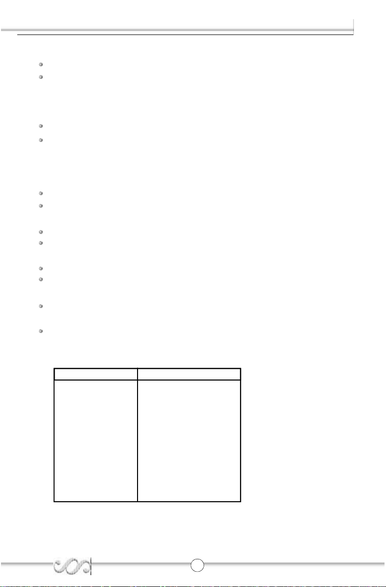
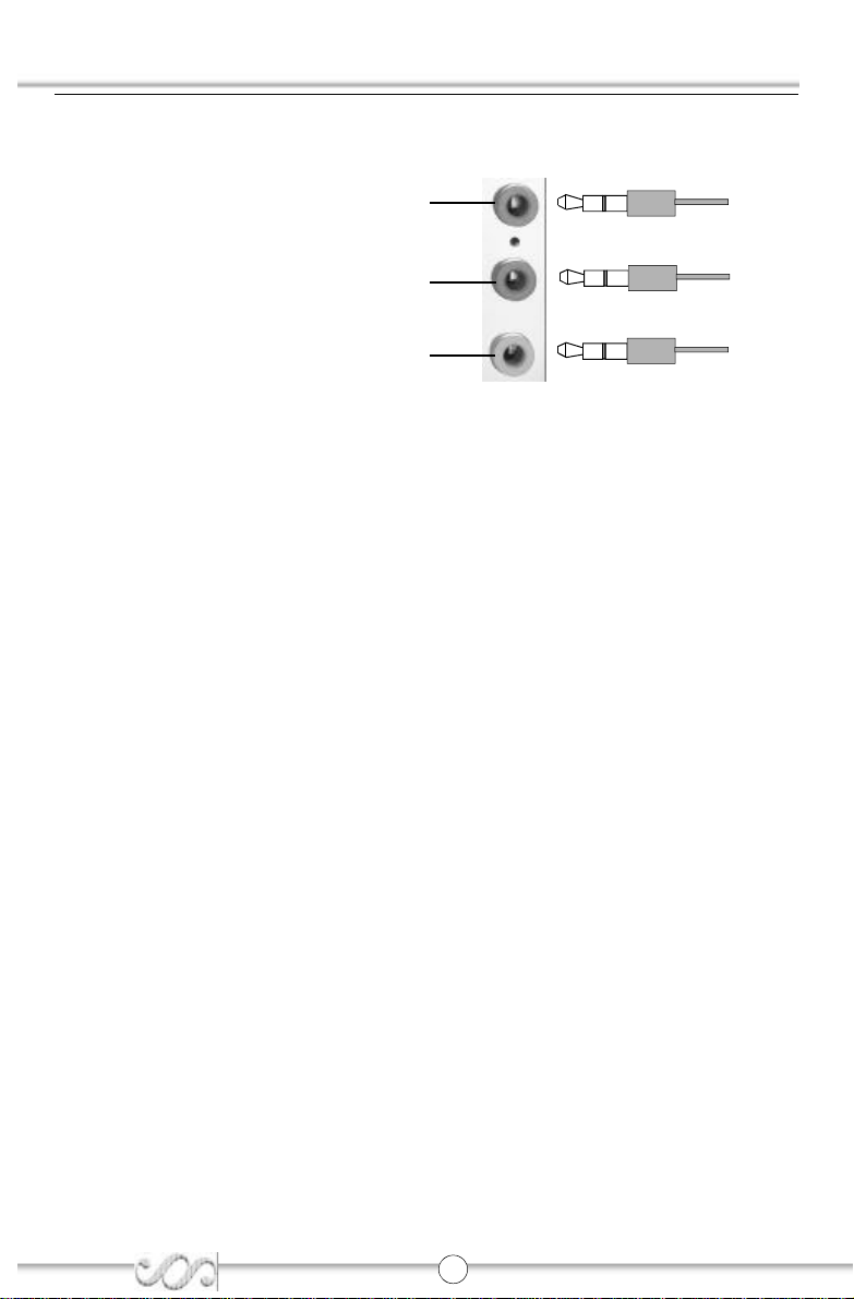
Line-in jack, Microphone-in jack and Speaker-out jack
The Line-in jack can be connected to devices such as a cassette or minid isc player to
playb ack or record. The Microphone-in jack can be connected to a microphone for voice
inp ut. The Speaker-out jack allows you to connect speakers or headphones for audio output
fro m the internal amplifier.
Line in
Speaker out
Microphone in
6-Channel Audio
This mainboa rd utilizes ALC655 chip providing 6-channel Audio, which consists of Front
Left, Front Right, Rear Left, Rear Righ t, Center and SubWoofer for a complete surround
sou nd effect. When 6-Channel audio is available, the front Left&Right jack can be connected
to the Front speskers, the Back Left&Right jack can be connected to the rear speakers and
the Cente r&SubWoofer jack can be connected to the center speaker and woofer.
Microphone function is offered b y F_AUDIO Connector on the mainboard now.
If set 2-Chan nel Audio mode on -6A or -6AL mainboard, you can connect two speakers to
the Front Left&Right jack, at the same time use the Rear Left&Right jack as Line in jack, and
use the Center&SubWoofer jack as Microphone in jack.
IEEE 1394 Port (optional)
The IEEE 1394 port is for conne cting IEEE 1394 device.
IEEE 1394 port
6
Rear Left&Right
Front Left&Right
Center&SubWoofer
K7N2S
Page 7
Chapter 2
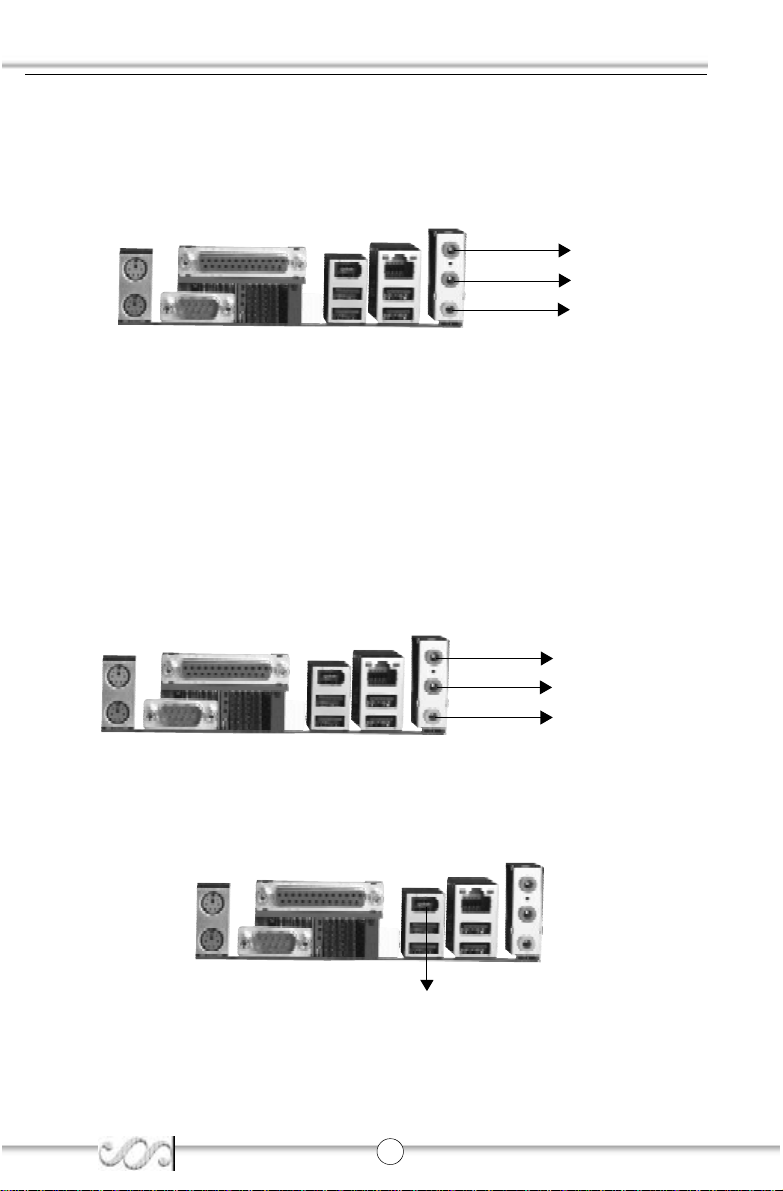
ATX Power Supply Connector & Power Switch (POWER SW)
The power switch (POWER SW) should be connected to a momentary switch. When
powering up your system, first turn on the mechanica l switch of the power supply (if one
is provided), then push once the power switch. When powering off the system, you
needn’t turn off the mechanical switch, just push once the power switch.
ATX Power Supply Connector
5V
GND
3.3V
1
POWER SW
3.3V
-12V 3.3V GND
GND 5V GND PS-OK
GND
PS-ON
GND GND
5VSB
12V
20
-5V
5V
5 V
Hard Disk LED Connector (HD_LED)
The conne ctor connects to the case’s IDE indicato r LED indicating the activity status of IDE
hard disk. The connector has an orientation. If one way doesn’t work, try the o ther way.
Reset Switch (RESET)
The connector connects to th e case’s reset switch. Press the switch once, the system
resets.
7
K7N2S
Page 8

Installation Instructions
Power LED Connector (PWR_LED)
When the system is in S0 status, the LED is on . When the system is in S1 status, the LED
is on; When the system is in S3,S4, S5 status, the LED is off. The connector has an
orientation .
POWER
Power SW
LED
RESET
G N D
Reserved
PWR LED(+)
PWR LED(-)
G N D
P O W E R
EMP TY
POWER LED
POWER SW
HD LED
HDD LED
RESET
HDD LED(+)
HDD LED(-)
P O W E R
REVERSE
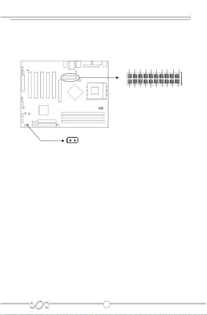
Fan Connectors (CPUFAN, SYSFAN)
The fan speed of these three fans can be detected an d viewed in the CMOS SETUP.
+12V
GND
SENSE
SENSE
GND
+12V
CPUFAN
SYSFAN
8
K7N2S
Page 9

Chapter 2
USB5,6; USB7,8
Beside s USB1,2,3,4 on the back panel, K7N2S series of mainboards also have 10-pin headers on boa rd which may connect to front panel USB cable( optional ) to provide additional four
USB ports.
USB5_6
USB7_8
GND
GND
USB+
USB-
+5V
GND
GND
USB+
USB-
+5V
CUT
GND
USB+
USB-
+5V
1
CUT
GND
USB+
USB-
+5V
1
Infrared Header (IrDA)
This connector supports wireless transmitting and receiving device.
1
VCC
IrDA
CUT
IRRX
GND
IRTX
Onboard SATA
The mainb oard provides two Serial ATA connectors, SATA is a storage interface that is
compliant with SATA 1.0 Specification. With speed of up to 150Mbps. you can connect
Serial ATA cable to Serial ATA hard disk.
9
S-ATA1/S-ATA2
GND
TX+
GND
RX-
RX+
GND
TX-
K7N2S
Page 10

Installation Instructions
Audio Connectors (CD_IN)(optional)
CD_IN is Sony standard CD audio connector, it can be connected to a CD-ROM drive
through a CD audio cable.
CD_IN
CD Left Channel
GND
CD Right Channel
Audio Interface(F_AUDIO)(Optional)
The audio interface provides two kinds of audio output choices: the FrontAudio and the
RearAudio. Their priority level is as sequence. When the FrontAudio is available, the
RearAudio will be cut off. An onboard amplifier is provided for the earphone. When the
FrontAudio is ab sent, Pin5 and Pin6, Pin9 and Pin10 must be short connected.
1
F_AUDIO
(Audio Interface)
Pin
No.
1 AUD_MIC 2 AUD_GND
3 AUD_MIC_BIAS 4 AUD_VCC
5 AUD_FPOUT_R 6 AUD_RET_R
7 NC 8 (Cut away)
9 AUD_FPOUT_L 10 AUD_RET_L
Symbol
3
5
7
9
Pin
No.
2
4
6
8
10
Symbol
1 0
K7N2S
Page 11

Chapter 2
SPDIF OUT Connector(optional)
The SPDIF output allow your digital audio input from digital audio device s.
GND
SPDIF out
Cut away
1
SPDIF
Front IEEE 1394 port(1394)(optional)
Beside s one 1394 port on the back panel, the mainboard also have one 10-pin headers on
board to p rovide additional IEEE 1394 port.
1 1
1394
Ground
12V(FUSE)
TPB-
Ground
TPA-
Ground
1
K7N2S
12V(FUSE)
TPB+
TPA+
Page 12

Installation Instructions
Jumper Settings
Jumpers are located on the mainboard, the clear CMOS jumper JCC, e nable keyboard
password p ower-on function jumper JKB etc. Pin 1 for all jumpers are located on the side
with a thick white line (Pin1→ ), referring to the mainboard’s silkscreen. Jumpers
with three pins will be shown as to represent pin1 & pin2 (“1-2”) closed and
to represent pin2 & pin3 (“2-3”) closed.
Jumper Symbol Descrip tion Represent
1-2 set pin1 and pin2 closed
2-3 set pin2 and pin3 closed
close set the pins closed
open set the p ins opened
Clear CMOS (CLR_CMOS)
If you want to clear CMOS, unplug the AC power supply first, close CLR_CMOS (pin2 &
pin1) once, set CLR_CMOS back to the normal status with pin3 & pin 2 connected, then
power on the system.
Clear CMOS
1 2
3
3
2
1
1 2
K7N2S
(Unplug the AC
power supply)
Normal status
Page 13

Chapter 2
BIOS-Protection Jumper (BIOS_WP)
The BIOS of the mainbo ard is inside the FWH. If the jumper BIOS_WP is set as closed, the
system BIOS is protected from being attacked by serious virus such as CIH virus, you
will be unable to flash the BIOS to the mainbo ard in this status.
BIOS_WP
Flash Write
Disabled
Flash Write
Enabled
Enable Front/Back Panel USB Device Wake-up Function (JUSB/JFUSB)
(optional)
The mainboard provides the ad vanced USB device wake-up function. The system can be
waked up from its power saving status including ACPI S3 by activating USB device.
Before us ing this function, set JUSB/JFUSB with pin1 & pin2 closed. Otherwise, set
JUSB/JFUSB with pin2 & pin3 closed for disabling.
JUSB
1
2
3
1
2
3
EnableDisable
1 3
JFUSB
1
2
3
1
2
3
EnableDisable
K7N2S
Page 14
Installation Instructions
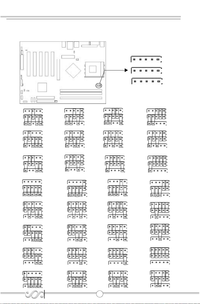
J1,J2,J3 Jumpers
Warning: Be sure your selection is right. CPU over speeding is dangerous! We will not be
responsible for any damages caused.
J3
J1
J2
J3
J1
J2
J3
J3
J3
J1
J2
J3
J1
J2
J3
J1
J2
J3
J1
J2
J1
J2
J1
J2
×5.0
×7.0
×9.0J3J1
×11.0
×13.0
×15.0
×17.0
J3
J3
J1
J2
J1
J2
J2
J3
J1
J2
J3
J3
J1
J2
J3
J1
J2
J1
J2
×5.5
J3
×7.5
×9.5
×11.5J3J1
×13.5
×22.0
×18.0
J3
J1
J2
J1
J2
J3
J1
J2
J2
J3
J1
J2
J3
J1
J2
J3
J1
J2
×6.0
×8.0
×10.0
×12.0
×14.0
×16.0
×23.0
J3
J1
J2
J3
J1
J2
J3
J1
J2
J3
J1
J2
J3
J1
J2
J3
J3
J1
J2
J1
J2
×6.5
×8.5
×10.5
×12.5
×21.0
×16.5
×24.0
J3
J1
J2
×3.0
J3
J1
J2
×19.0
1 4
J3
J1
J2
×4.0
J3
J1
J2
K7N2S
×20.0
Page 15
Chapter 3
Chapter 3
BIO S Description
The mainboard uses AMI BIOS Setu p program that provides a Setup
utility for use rs to modify the basic system configuration. The information is stored in CMOS RAM so it retains the Setup information
even if the power is turned off. This chapter provides you with the
overview of the BIOS Setup.
1 5
K7N2S
Page 16

BIOS Description
AMIBIOS Flash Upgrade Method
NVFLASHS
NVFLASHS is a package of utilitie s used to update the system BIOS, NVFLASHS works in
DOS environmen t.
Before upgrading your BIOS, please note:
We s trongly recommend you only upgrade BIOS when encounter problems.
Before upgrading your BIOS, review the description below to avoid making
mistakes,destroying the BIOS and resulting in a non-working system.
When you encounter problems, for example, you find your system does not support the
latest CPU released after our current mainboard, you may th erefore upgrade the BIOS,
please do n’t forget to set BIOS_WP as open and disable the “BIOS Write Protect” item in AMI
BIOS CMOS Setup first .
Below is the option for this program:
-f <filename> Flash the ROM using <filename>
-v or -va Verify the file matches the ROM (the e ntire ROM)
-vm:ESCD Verify the file matches the ROM but mask the ESCD range
-vm:03000-03fff Ve rify the file matches the ROM but mask 03000-03fff
-vr:001 00-00200 Verify the rang e in the file from 00100-00200
-u Up date UUID
-igp64 -igp128 Force ramwidth in NB ROM tables to 64 or 128
-i Ignore errors in file (flash BIOS reguard less)
-c Cle ar CMOS
-l Set RomTable LOCKOUT bit
-QuickFlash Reflashes sectors only if the y differ from new image
-mb <moth erboard> Motherboard specific
Follow the steps exactly for a successful upgrade.
1. Create a bo otable system floppy diskette by typing Format A:/s from the DOS prompt
under DOS6.xx or Windows 9x environment.
2. Copy NVFLASHS.EXE from the directory \Utility located on QDI Utility CD to new
bootable diskette.
3. Download the up dated BIOS file from the Website (http://www.qdigrp.com). Please
be sure to download the suitable BIOS file for your motherboard.
4. Decompress the file download, copy the BIOS file (xxx.ROM) to the bo otable diskette.
5. Reboot the system from the b ootable diskette created.
6. Then run the NVFLASHS utility at the A:\ prompt as shown below:
A:\NVFLASHS -f xxx.ROM
Follow the instruction through the process. Don’t turn off power or reset the system
until the BIOS u pgrade has been completed.
A Note:
Because the BIOS Software will be updated constantly, the following BIOS screen and descriptions are for re ference purposes only
and ma y not reflect your BIOS screens exactly.
1 6
K7N2S
Page 17

Chapter 3
AMI BIOS Description
Entering Setup
Power on the computer, when the following message briefly appears at the bottom of
the screen durin g the POST (Power On Self Test), press <Del> key to enter the BIOS
CMOS Setup Utility.
Press <Del> to enter SETUP
When you have entered, the Main Menu appears o n the screen. Use the arrow keys to
select among the items an d press the <Enter> key to accept or enter the sub-menu.
Main Menu
Main Setup
The main settings configure BIOS information such as version , ID,build date and system
Date, Time, processor Types and speed etc. Use the arrow keys to highlight the item,
then use the <PgUp> or <PgDn> keys to select the value d esired in each item.
Advanced BIOS Setup
This section configure CPU options, IDE device, Floppy drive, boot settings , superIO
chipset, h ardware health, ACPI, USB support etc.
PCI PnP Setup
This section describ es how to configure the PCI bus system. This section covers some
very technical items and it is recommen ded that only experienced users should make any
changes to the default setting.
Boot Settings
The section allo w you to configure settings during system boot.
Security Settings
Changes, sets, or disables password. It allows you to c onfigure boot sector virus
protection.
Chipset Setup
The chipset features setup is used to change the values of the chipset registers. The
registers control most of the system options in the computer.
Power Management Setup
The power management setup menu allows you to configure APM.
Exit Setup
The section allow you to configure exit options, load Optimal Defaults and load failsafe
defaults etc.
Note: if you need detailed information about BIOS, please view them in the CD.
1 7
K7N2S
Page 18

Appendix
Appendix
QDI Utility CD
A QDI Utility CD is supplied with this mainboard, th e contents contained in it are showed
as below:
1. Driver Install
Using this choice, you can install all the drivers for your main board . You should install
the drivers in order, and you need to restart your computer until all the drivers are
insta lled.
A. DirecrX B. Chipset Software
C. USB2.0 (optional) D. Audio Driver(optional)
2. Browse CD
You could read all the contents contained in this CD, including Utility a nd Documents.
The files included in Utility are:
A. nvflashs.exe
The files included in Documents are:
A. Adobe Acrobat Reader V5.0 B. BIOS manual_ch
C. BIOS manu al_en
1 8
K7N2S
Page 19

Appendix
Instalación de la placa base QDI K7N2S(Spanish):
1. Asegúrese que se incluyen los siguientes artículos: Placa base QDI K7N2S, 1 cable
de datos para el pu erto IDE y 1 cable de datos para el Floppy, jumpers, 1 manual de
usuario QDI K7N2Sy un disco compacto con los controladores de la placa base QDI
K7N2S.
2. Asegúrese de que el cable de la fuente de alimentación esta desconectado y
asegúrese de estar en contacto a masa utilizando una pulsera antiestática. Si no
dispone de d icha pulsera, toque un objeto directamente conectado a masa o una
parte metálica de su equipo como puede ser la caja de este.
3. Fije la placa base en la caja de su equipo con los tornillos especiales que acompañan
a su caja.
4. Los jumpers están localizados en la placa base, con ellos se configuran, por ejemplo:
Clea r CMOS CLR_CMOS, Habilitar BIOS ProtectEasy BIOS_WP etc… , el PIN1 para
todos los jumpers e sta marcado con una línea más gruesa (Consulte el apartado
“Jumper Settings” en el manual de usuario de su placa QDI K7N2S en el capítulo 2).
5. Inserte el procesador en el socket y conecte el ventilador del procesador en el
cone ctor de su placa base QDI K7N2S marcado como “CPUFAN”.
6. Inserte los módulos de memoria en los bancos de memoria DIMM de su placa base QDI
K7N2S.
7. Inserte las tarjetas PCI y/o la tarjeta AGP en las bahías de expan sión de su placa base
QDI K7 N2S.
8. Conecte los periféricos internos IDE y las disqueteras mediante los cables de datos
específicos a su placa base QDI K7N2S. Asegúrese que la orientación de los cables
sea la correcta. (El ca ble rojo se corresponde con el pin 1).
9. Conecte los cables de la caja del ordenador a su placa base QDI K7N2S, como el
conector de la fuente de alimentación, los testigos de corriente, y lectura de disco
duro, interruptores d e inicio y reset (consulte el apartado “External Connectors” del
manua l de usuario de su placa base QDI K7N2S).
10. Conecte los diferentes periféricos externos como el te clado PS/2, ratón PS/2, serie o
USB, los dispositivos USB, el monitor y la impresora a la pla ca base QDI K7N2S
(consulte el apartado “External Connectors” en el manual de su placa base QDI
K7N2S, en el capítulo 2).
11. Cuando haya finalizado de realizar todas las conexiones, conecte el cable de
alime ntación a la fuente de alimentación y encienda su PC:
1 9
K7N2S
Page 20

Appendix
Instalación del sistema:
1. Encienda su equipo mediante el interuptor de encendido de la caja.
2. Presione la tecla « Sup r » para entrar en el menú de configuración de la BIOS.
3. Seleccione los valores de la Bios en concordancia con la configuración de su sistema
(Nosotro s le recomendamos que deje los valores establecidos por la Bios por defecto,
para evita r posibles fallos que ocasionen que su sistema no funcione correctamente).
Para más información las funciones de la Bios, consulte el apartado “BIOS Description”
en el manual de usuario d e la placa base QDI K7N2S). Presione la tecla « F10 » y
seleccione la opción “Save & Exit Setup ” en el menú de configuración de la Bios para
guarda r los cambios y reiniciar el sistema.
4. Instale el sistema operativo en el disco duro, no se olvide de seleccionar la secuencia
de inicio correcta para que el sistema operativo pueda iniciarse.
5. Después de la instalación del sistema operativo, asegúrese que no hay conflictos con
ningún dispositivo de su sistema.
6. Entonces, después del último paso, proceda a la instalación d e los controladores de
los diferentes disp ositivos.
Un disco compacto con controladores de QDI esta incluido en el
paquete de la placa base QDI K7N2S.
1. Instalación de los controladores
Usted puede instalar to dos los controladores para su placa base facilmente. Tiene que
instalar los controladores en el siguiente orden para un correcto funcionamiento del
sistema, y es necesario reiniciar el equipo antes de finalizar la instalacción de los
controla dores.
A. DirecrX B. Chipset software
C. USB2.0 (optional) D. Audio Driver(optional)
2. Navegue por el CD
Usted puede le er todos los documentos incluidos en este CD, incluidos
Utility and Docume nts.
Los ficheros incluidos en Utility son:
A. nvflashs.exe
2 0
K7N2S
Page 21

Appendix
Manuel d’installation des cartes mères de la série QDI
K7N2S (French):
Intégration du système :
1. Vérifier la présence de chaque élément dans la boite de la carte mère de la série QDI
K7 N2S :
Une carte mère de la série QDI K7N2S.
Un CD-ROM d’insta llation QDI.
Un manuel d’utilisation de la carte mère QDI K7N2S.
Un sachet de cavaliers.
Une nappe IDE compatible avec la norme ATA/66 destinée au lecteur de
disq ue dur.
Une nappe destinée au lecteur de disquette.
Un fond de panier métallique destiné à l’unité cen trale de l’ordinateur
(Ca ractéristique technique optionnelle).
Un câble d’extension destiné à p ermettre l’exploita tion des ports USB 3 et
USB 4 ou USB 5 et USB 6 (Caractéristique technique optionnelle).
2. Vérifier que le câble électrique relié au boîtier d’alimentation de l’unité centrale de
l’ordinateur est déconnecté. Se relier à la terre grâce à un bracelet lié au poignet. A
défaut de disposer d’un bracelet, maintenir un contact physique avec un objet luimême relié à la terre, ou à une partie métallique du système comme la structure de
l’unité centrale de l’ordinateur.
3. Fixer la carte mère dans l’unité centrale de l’ordinateur grâce aux vis fournies avec
cette dernière lors de son achat.
4. S’assure r que la carte mère de la série QDI K7N2S est matériellement correctement
configurée, pour cela vérifier que les cava liers insérés sur les broches intégrées de
cette dernière sont correctement positionnés. Dans ce but il est important de se
référer à la se ction nommée « Configuration des cavaliers » du chapitre numéro 2
nommé « Instructions d’installation » contenu dans le manuel d’utilisation livré avec la
carte mère de la série QDI K7N2S lors de son achat.
5. Connecter le processeur dans le socket intégré à la carte mère de la série QDI K7N2S
et prévus à cet effet. Fixer le système de refroidissement de ce dernier e t connecter
son ventilateur sur les broches nommées « CPUFAN » intégrées à la carte mère de la
série QDI K7N2S et prévus à ce t effet.
6. Connecter les éventuelles barrettes de mémoire dans les slots intégrés à la carte
mère de la série QDI K7N2S et prévus à cet effet.
7. Connecter les éventuelles cartes d’extension au format AGP, PCI dans les slots
intégrés à la carte mère de la série QDI K7N2S et prévus à cet effe t
8. Connecter les éventuels périphériques IDE ainsi que le lecteur de disquette à la carte
mère de la série QDI K7N2 S grâce aux nappes fournies avec cette dernière lors de
son achat. S’assurer que l’orientation des nappe s connectées est correcte en vérifiant
2 1
K7N2S
Page 22

Appendix
que le liseré rouge de ces dernières correspond à l’emplacement de la broche numéro
1 du connecteur.
9. Connecter les câbles de l’unité centrale de l’ordinateur sur les broches intégrées à la
carte mère de la série QDI K7N2S et prévues à cet effet. Dans ce but il est important
de se référer à la section nommée « Connecteurs externes » du ch apitre numéro 2
nommé « Instructions d’installation » contenu dans le manuel d’utilisation livré avec la
carte mère de la série QDI K7N2S lors de son achat.
10. Racco rder les périphériques externes sur les connecteurs de fond de panier intégrés
à la carte mère d e la série QDI K7N2S. Dans ce but il est important de se référer à la
sectio n nommée « Connecteurs e xternes » du chapitre numéro 2 nommé « Instructions
d’installation » contenu dans le manuel d’utilisation livré avec la carte mère de la série
QDI K7N2S lors de so n achat.
11. Lorsque tous les éléments du système sont correctement intégrés, il est possible de
reconnecter le câble électrique au boîtier d’alimentation de l’unité centrale de l’ordinateur.
Installation du système :
1. Démarrer le système en pressant l’interrupteur d e fonctionnement de l’unité centrale
de l’ordinateur.
2. Presser la touche “Suppr” du clavier afin d’entrer dans le menu de BIOS.
3. Dans le menu de BIOS nommé “QDI Innovation features”, ajuster la fréquence de
fonctionnement du processeur. Atte ntion, il est fortement recommandé de charger
les réglages de sûreté par défaut afin d’éviter un éventuel dysfonctionnement du
système. Dans ce but il est important de se référer à la section nommée « Description
du BIOS Award » du chapitre numéro 3 nommé « Description du BIOS » contenu dans
le manuel d’utilisation livré ave c la carte mère de la série QDI K7N2S lors de son achat.
4. Procéder à l’installation du système d’exploitation sur le lecteur de disque dur intégré
au système. Dans ce but il est important de vérifier que la séquence de démarra ge du
système pa ramétrable à partir du menu de BIOS permet à la procédure d’installation
du système d’exploitation de s’initialiser.
5. Une fois l’installation du système d’exploitation achevée, vérifier qu’il ne subsiste
aucun conflit ou p ériphérique inconnu au sein du système.
6. Après ce tte étape, procéder à l’installation des pilotes de chaque périphérique détecté
par la carte mère de la série QDI K7N2S.
2 2
K7N2S
Page 23

Appendix
Lors de son achat un CD-ROM d’installation QDI est livré avec la carte mère de
la série QDI K7N2S.
1. Driver Ins tall :
Avec cette option, il est possible d’installer les pilotes de la carte mère de la série QDI K7N2S
aisément. Il est important d’installer les pilotes en respectant l’ordre prédéfinit et de redémarrer
le système après avoir e ffectué l’installation de tous les pilotes.
Applications conte nues dans le dossier :
A. DirectX B. Chipset software
C. USB2.0 (optional) D. Audio Driver(optional)
2. Browse CD :
Avec cette option, il est possible de consulter l’ensemble des données contenues
sur le CD-ROM d’installation QDI
Applications contenue s dans le dossier :
A. nvflashs.exe.
2 3
K7N2S
Page 24

Appendix
QDI K7N2S installazione mainboard (Italian):
1. Assicurarsi che la scatola sia completa: QDI K7N2Smain board, cavo IDE e Floppy,
jumpers, manuale dell’utente della mainboard QDI K7N2S e cd-rom drivers.
2. Controllare che il cavo alimen tazione proveniente dal computer-case sia sconnesso
assicu rarsi inolre di aver indossato corretamente il bracciale da polso collegato a massa.
In mancan za di questo toccare un punto a massa o una parte metallica del case
3. Fissare la main board nel case con le speciali viti fornite con il computer-case
4. I jumper loca ti sulla mainboard rappresentano: CLR_CMOS azzeratore BIOS, BIOS_WP
abbilitatore/disabbilitato re in BIOS della funzione protectEasy; per tutti i jumper il PIN 1 e’
contrassegn ato da un spessa linea bianca ( consultare il manuale al capitolo 2 “ JUMPER
AND SETTINGS”)
5. Inserire il processore nell’apposito slot ; la ventola del processore deve essre collegato
nello speciale connettore targato “ CPUFAN ”.
6. Inserire il modulo/i di memoria nell’apposito memory slots
7. Inserire le periferich e Pci negli appositi Pci slots
8. Collega re le periferiche IDE e il FLOPPY con l’apposito cavo fornito con la mainboard
negli specifici connetori marcati. Assicura rsi che l’orientamento del cavo sia corretto. ( La
linea rossa sul cavo deve essere inserita nellapposito connettore in corispondezza del pin
1)
9. Conettere la mainboard con: il cavo di alimentazione proveniente dall’alimentatore, il
connettore dell’interuttore di stand by, il conettore del led di segnalazione “acceso”, il
conne ttore led di funzionalita’ HARD DISK, il connettore dello spekear interno al CASE.....
( consultare il manuale capitolo 2. “ EXTERNAL CONNECTORS ”. Dopo chiu dere il CASE)
10.Connettere le differenti periferiche estern e come il PS/2 mouse, la PS/2 tastiera, le prese
USB, il monitor e la stampante co n gli specifici connettori posizionati sulla faccia esterna
della mainboard.
11. Quando la vostra configurazione sara’ tutta connessa, agg angiare il cavo di
alimenta zione.
Installazione di sistema
1. Portare in po sizione di acceso l’interu ttore di ACCESO
2. Usare il tasto DEL per entrare nel nel software di config urazione del BIOS
3. Regolare le funzioni del BIOS in accordo con la configurazione di sistema ( Noi ti
raccomandiamo di usare l’impostazione di default per evitare rischi di anomalie di
funz ionalita’). Per maggiori informazioni controllare il capitolo 3, sezione “BIOS
DESCRIPITION”. Premere F10 sulla tastiera o scegliere “SAVE and EXIT” dal menu di BIOS
per salvare le imp ostazioni scelte ed uscire dal BIOS program.
4. Installa re il sistema operativo , non dimenticando di mettere nelle giuste condizioni di
partenza la se quenza di boot.
5. Dopo una g iusta installazione accertarsi che non vi siano conflitti tra le periferiche in
2 4
K7N2S
Page 25

Appendix
uso
6. Dopo questo ultimo passo procedere all’installa zione dei driver delle varie periferiche
IL CD CONTENENTE I DRIVER DELLA VOSTRA MAINBOARD QDI
E’CONTENUTO NELLA SCATOLA
1. Installazione driver
E p ossibile installare tutti i driver della Vs. mainboard in modo facile e veloce.
Dovreste in stallare i driver nella seguente succesione, finito cio’ biso gna far
ripartire il personal computer.
A. DirectX B. Chipset software
C. USB2.0 (optiona l) D. Audio Driver(optional)
2. Guardando il CD
Que sto manuale di installazionee’ disponibile anche nella sua versione elettronica all’interno
del cd accompa gnativo, insieme anche diverse utili quali:
A. nvflashs.exe
2 5
K7N2S
Page 26

Appendix
Using 4-/6-Channel Audio(4-/6- Channel Audio Interface)
The motherboard is equipped with Realtek ALC655 chip, which provides support for 6channel audio output, including 2 Front, 2 Rear, 1 Center and 1 Subwoofer channel.
ALC655allows the board to attach 4 or 6 speakers for better surround sound effect. The
section will tell you how to install and use 4/6-channel audio function on the board.
Installing the Audio Driver
The Realtek ALC655 chipset driver has to be installed before the 4-/6-Channel audio
function can be used.
Using 4-/6-channel Audio Function
You can start to use the 4-/6-channel audio function After the driver is installed completely.
The first, you can connect 4 or 6 speakers to the audio output connector. Then open utility
to set the work parameter.
Attaching speakers
To perform multichannel audio operation, connect multiple speakers to the system. You
should connect the same number of speakers as the audio channels you will select in the
software utility.
2-Channel Analog Audio Output
Line In
Line Out (Front channels)
MIC
Description: Line Out, Line In and MIC functions all exist under 2-channel
configuration.
4-Channel Analog Audio Output
Line Out(Rear Channels)
Line Out (Front channels)
MIC
Description: Line In is converted to Line Out function under 4-channel configuration.
2 6
K7N2S
Page 27
Appendix
6-Channel Analog Audio Output
Line Out(Rear Channels)
Line Out (Front channels)
Line Out(Center & Subwoofer Channels)
Description: Both Line In and MIC are converted to Line Out function under 6-
channel configuration.
2 7
K7N2S
Page 28

Appendix
Selecting 4- or 6-Channel Setting
1. Click the audio icon from the window tray at the bottom of the screen.
2. Select any surround sound effect you prefer from the “Environment” pull-down
menu under the Sound Effect tab.
Click here and the pulldown menu will appear
3. Click the Speaker Configuration tab.
2 8
Click here
K7N2S
Page 29

Appendix
4. The following window appears.
Headphone Output
2 Channels Output
4 Channels Output
6 Channels Output
Keep
UnSelect
Status
5. Select the multi-channel operation you prefer from No. of Speakers.
6. Click OK
Testing the Connected Speakers
To ensure 4- or 6-channel audio operation works properly, you may need to test each
connected speaker to make sure every speaker work properly. If any speaker fails to
sound, then check whether the cable is inserted firmly to the connector or replace the
bad speakers with good ones.
Testing Each Speaker
The following window appears.
1. Click the audio icon from the window tray at the bottom of the screen.
2. Click the Speaker Test tab.
3. The following window appears.
Center
Front Left
Front Right
Rear Left
4. Select the speaker which you want to test by clicking on it.
2 9
Rear Right
Subwoofer
K7N2S
Page 30

Appendix
Playing KaraOK
The KaraOK function will automatically remove human voice (lyrics) and leave me-lody
for you to sing the song. The function is applied only for 2-channel audio opera-
tion, so make sure channel mode is selected in the “No. of Speakers” column before
playing KaraOK.
Playing KaraOK
1. Click the audio icon from the window tray at the bottom of the screen.
2. Make sure the Sound Effect tab is selected.
3. Select Voice Cancellation in the “Karaoke” column.
Click This
4. Click OK.
3 0
K7N2S
Page 31
Appendix
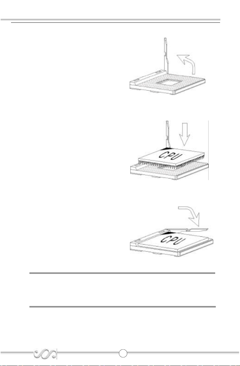
CPU Install ation Procedures
1.Pull the lever sideways away from
the socket. Then , raise the lever up
to a 9 0-degree angle.
2.Look for the cut edge. The cut edge
should point to wards the lever pivot.
The CPU will only fit in the correct
orien tation. If the CPU is correctly
installed, the pins shou ld be complete ly embedded into the socket
and ca n not be seen.
3. Hold the CPU down firmly, and then
close the le ver to complete
installation.
Warning: Ove rheating will seriously damage the CPU and system, always
make sure the cooling fan can work properly to protect the CPU
from overheating.
3 1
K7N2S
Page 32

Board Layout of
K7N2S
Note:
The layout includes all options.
It is for your reference only.
Page 33

F_AUDIO
Top :Line in
Midd: Spk out
Bttm:Mic in
Top :LAN(option)
Bttm:USB3,4
Top :1394
Bttm:USB1,2
LPT
COM1
Top :PS/2 Mouse
Bttm:PS/2 Keyboard
CD_IN
BIOS_WP
FDD
PCI 5
PCI 4
PCI 3
PCI 2
IrDA
1394
SPDIF
South Bridge
JFUSB
CLR_CMOS
USB5
_
6
USB7
_
8
2
1
F_PANEL
3
Note: pin1 for a jumpers are located on the side with black line.
1. PWR_LED 2. PWR_SW * EMPTY 3. HDD_LED 4. RESET * REVERSE
4
S-ATA1
S-ATA2
IDE1
*
*
IDE2
PCI 1
SYS_FAN
DIMM1
DIMM2
DIMM3
AGP
ATX_POWER
JUSB
North Bridge
CPU_FAN
Socket
A
J3
J1
J2
 Loading...