

Page 1

Item Checklist
This item checklist is only available for retail market.Completely check your package,If you
discover damaged or missing items, contact your retailer.
J6A series mainboard
QDI Driver CD
Users manual
1 IDE ribbon cable
1 floppy ribbon cable
I/O shield(option)
1 10-pin ribbon cable with bracket for USB (optional)
Notice
The information in this document is subject to change in order to improve reliability, design, or
function without prior notice and does not represent a commitment on the part of this company.
In no event will we be liable for direct, indirect, special, incidental, or consequential damages
arising out of the use or the possibility of such damages.
All trademarks are the property of their respective owners.
If you require further information, please visit our web-site: www.qdigrp.com.
J6AenÐòÑÔ.p65 02-7-29, 9:551
Page 2

Declaration of Conformity
QUANTUM DESIGNS(HK) LTD.
20th Floor, Devon House, Taikoo Place, 979 Kings Road,
Quarry Bay, Hong Kong
declares that the product
Mainboard
J6A
is in conformity with
(reference to the specification under which conformity is declared in
accordance with 89/336 EEC-EMC Directive)
!"EN 55022 Limits and methods of measurements of radio disturbance
characteristics of information technology equipment
!"EN 50081-1 Generic emission standard Part 1:
Residential, commercial and light industry
!"EN 50082-1 Generic immunity standard Part 1:
Residential, commercial and light industry
European Representative:
QDI COMPUTER( UK ) LTD. QDI COMPUTER( SCANDINAVIA )A/S
QDI SYSTEM HANDEL GMBH QDI EUROPE B.V
QDI COMPUTER( FRANCE ) SARL QDI COMPUTER HANDELS GMBH
LEGEND QDI SPAIN S.L. QDI COMPUTER( SWEDEN )AB
Signature : Place / Date : HONG KONG/2002
Printed Name : Xu Wenge Position/ Title : Assistant President
J6AenÐòÑÔ.p65 02-7-29, 9:552
Page 3

Declaration of Conformity
Trade Name: QDI Computer ( U. S . A. ) Inc.
Model Name: J6A
Responsible Party: QDI Computer ( U. S. A.) Inc.
Address: 41456 Christy Street
Fremont, CA 94538
Telephone: (510) 668-4933
Facsimile: (510) 668-4966
Equipment Classification: FCC Class B Subassembly
Type of Product: Motherboard
Manufacturer: Quantum Designs (HK) Ltd.
Address: 20th Floor, Devon House, Taikoo Place
979 Kings Road, Quarry Bay, HONG
KONG
Supplementary Information:
This device complies with Part 15 of the FCC Rules. Operation is subject to
the following two conditions : (1) this device may not cause harmful
interference, and (2) this device must accept any interference received,
including interference that may cause undesired operation.
Tested to comply with FCC standards.
Signature : Date : 2002
J6AenÐòÑÔ.p65 02-7-29, 9:553
Page 4

CONTENTSCONTENTS
CONTENTS
CONTENTSCONTENTS
1. Introduction .................................................... 1
Overview.................................................................... 1
Key Features ..............................................................1
2. Installation Instructions ..............................5
External Connectors.................................................... 5
PS/2 Keyboard /Mouse Connector.............................. 5
USB1, USB2 and LAN Connectors ............................. 5
Line-in jack, Mic-in jack, Speaker-out jack and
MIDI/Joystick Connector ..............................................6
Parallel Port, Monitor Output Connector(VGA),
Video/SPDIF and S-video out Connector.....................6
Hard Disk LED Connector ( HD_LED ) .........................6
Reset Switch ( RESET ).............................................6
ACPI LED Connector( ACPI_LED ) .............................. 7
ATX 12V Power Supply Connectors
and Power Switch (POWER SW) ................................7
USB3, 4 and Serial Port Connector ..............................8
Infrared Header ( IrDA ) ...............................................8
Fan Connectors(CPUFAN BAKFAN CHSFAN)..............9
Audio Connectors ( AUXIN, CD_IN ) ........................... 9
IEEE 1394 Connector( JFIR1,2 ) ................................ 10
Jumper Setting ........................................................... 11
BIOS-ProtectEASY Jumper( JAV ) ............................ 11
Clear CMOS( JCC ) ................................................... 12
Enable Video/SPDIF Out( JTV ) ................................. 12
3. BIOS Description................................13
Utility Support.............................................. 13
AWDFLASH.EXE ...................................................... 13
AWARD BIOS Description
Entering Setup ...........................................................14
Load Optimized Defaults ...........................................14
Standard CMOS Features Setup................................14
............................... 14
II
J6AenÐòÑÔ.p65 02-7-29, 9:554
Page 5

CONTENTSCONTENTS
CONTENTS
CONTENTSCONTENTS
Advanced BIOS Features Setup.................................... 18
Advanced Chipset Features Setup................................ 21
Power Management Setup............................................. 23
PnP/PCI Configurations Setup......................................... 26
Integrated Peripherals.....................................................27
PC Health Status............................................................. 29
Password Setting...........................................................31
Boot with BIOS defaults................................................. 31
Appendix....................................................................32
QDI Utility CD...................................................................32
Norton AntiVirus.........................................................32
LogoEasyII.................................................................33
BIOS-ProtectEasy......................................................34
RecoveryEasy............................................................35
BootEasy...................................................................43
BootEasy(German)....................................................44
J6A(Spanish).............................................................45
J6A(French)...............................................................48
J6A(Italian).................................................................52
Layout
J6AenÐòÑÔ.p65 02-7-29, 9:555
Page 6

Caution
Be sure to unplug the AC power supply before adding or removing
expansion cards or other system peripherals, especially the memory
devices, otherwise your mainboard or the system memory might be
seriously damaged.
Caution
Be sure to add some Silicone Grease between the CPU and the heatsink
to keep them fully contacted to meet the heat sink requirement.
J6AenÐòÑÔ.p65 02-7-29, 9:556
Page 7

Chapter 1
Chapter 1
Introduction
Overview
J6A series are multimedia, high performance, cost-effective and energy efficient
mainboards based on VIA C3 BGA processors. The green mainboard utilizes the VIA
Apollo PLE133 chipset consisting of the VIA VT8601A and the VIA VT82C686B. The
chipset integrates AGP 2D/3D graphics accelerator to provide high graphics
performance. It supports the Ultra DMA33/66/100 IDE, PC100/PC133 SDRAM and AC97
audio. In addition, advanced features are supported such as ACPI power management
and hardware monitoring. Especially it supports television display and IEEE1394, which
is ideal for playing games, giving presentations, watching movies, and browsing the
Internet with a high quality TV image. BootEasy, QDI innovation, lets the PC boot freely
and rapidly.
Key Features
Form Factor
# mATX form factor of 220mm x 210mm
Microprocessor
#"Supports all VIA C3 BGA processors at 500/550/566/600/667/733/866MHz and
future processors.
Chipset
#" VIA Apollo PLE133 chipset: VT8601A + VT82C686B
Memory
#" Provides one 168-pin 3.3V 100/133MHz DIMM socket
#"Supports PC100/PC133 SDRAM
Onboard IDE
""
##
#
"Two fast IDE interfaces supporting four IDE devices including IDE hard disks and
##
""
CDROM drives
""
##
#
"Supports Ultra DMA33/66/100
##
""
Manual for J6A series
J6Aen.p65 02-7-29, 9:551
1
Page 8

Introduction
Onboard I/O
""
##
#
"One floppy port supporting up to two 3.5 or 5.25 floppy drives with 360K/720K/
##
""
1.2M/1.44M/2.88M format
""
##
#
"Two high speed 16550 fast compatible UARTs(COM1/COM2/COM3/COM4
##
""
selective) with 16-byte send/receive FIFO
""
##
#
"One parallel port supports SPP/EPP/ECP mode
##
""
""
##
#
"Supports PS/2 mouse and PS/2 keyboard
##
""
""
##
#
"Provides four USB
##
""
""
##
#
"Provides one IrDA connector
##
""
""
##
#
"Provides two IEEE 1394 connectors
##
""
""
##
#
"Provides one S-Video out connector
##
""
""
##
#
"Provides one Video/SPDIF connector
##
""
Onboard Audio
""
##
#
"Standard AC97 Codec interface
##
""
#" Provides onboard Line-in Jack, Microphone-in Jack, Speaker-out Jack with onboard
amplifier and MIDI/Joystick Connector
Onboard AGP
""
##
#
"Supports AGP 4x
##
""
""
##
#
"Integrated 2D/3D Graphics Controller
##
""
Onboard LAN( optional )
""
##
#
"10/100M LAN interface built-in on board
##
""
""
##
#
"10/100M Ethernet support
##
""
Advanced Features
""
##
#
"PCI 2.2 Specification Compliant
##
""
""
##
#
"Provides Trend ChipAwayVirus On Guard
##
""
""
##
#
"Supports Windows 98/2000/ME/XP soft-off
##
""
""
##
#
"Supports system monitoring (monitors system temperature, CPU temperature, voltages
##
""
and fan speed)
""
##
#
"Provides the second PCI connector to support two additional PCI connectors
##
""
""
##
#
"Providing QDI innovations: BootEasy, logoEasy, BIOS-ProtectEasy, RecoveryEasy
##
""
J6Aen.p65 02-7-29, 9:552
Manual for J6A series
Page 9

Chapter 1
BIOS
##
# Licensed advanced AWARD( Phoenix ) BIOS
##
##
""
#
" Supports Flash ROM with plug and play ready
##
""
##
# Supports IDE CDROM/SCSI bootup
##
Green Function
##
""
#
" Supports ACPI (Advanced Configuration and Power Interface) and ODPM (OS Di-
##
""
rected Power Management)
#" Supports ACPI power status: S0( Full-on ), S1( Suspend ), S4(STD,suspend to Disk,
depends on OS ), S5(Soft-off)
Main Expansion Slots and Connectors
Slot/Port (Quantity) Description
PCI( 2 ) PCI slots
IDE( 2 ) IDE ports
FLOPPY( 1 ) Floppy Drive port
DIMM( 1 ) DIMM socket
USB( 4 ) USB connectors
VGA( 1 ) VGA connector
LAN( 1 ) LAN connector
UART( 2 ) UART connectors
PARALLEL( 1 ) Parallel connector
IrDA( 1 ) IrDA connector
MIDI/Joystick( 1 ) MIDI/Joystick connector
IEEE 1394(2 ) IEEE 1394 connectors
S_video out ( 1 ) S_video out connector
Video/SPDIF( 1 ) Video/SPDIF connector
Note: Our technology is now being upgraded, the description and Interface for
Easy technology in this manual are only for your reference. If you would like to
get the upgraded version, please download the latest BIOS or the utility from the
website to re-flash your mainboard; if your mainboard supports the latest version
Easy technology, refer to the webpage for functions and detailed operation of
the technology.
Manual for J6A series
J6Aen.p65 02-7-29, 9:553
3
Page 10

-- This page is intentionally left blank --
J6Aen.p65 02-7-29, 9:554
Page 11

Chapter 2
Chapter 2
Installation Instructions
This section covers External Connectors and Jumper Settings. Refer to the motherboard
layout chart for the locations of all jumpers, external connectors, slots and I/O ports.
Furthermore, this section lists all necessary connector pin assignments for your reference.
The particular states of the jumpers, connectors and ports are illustrated in the following
figures. Before setting the jumpers or inserting these connectors, please pay attention to
the directions.
External Connectors
PS/2 Keyboard Connector, PS/2 Mouse Connector
PS/2 keyboard connector is for the usage of PS/2 keyboard. If using a standard AT size
keyboard, an adapter should be used to fit this connector. PS/2 mouse connector is for the
usage of PS/2 mouse.
PS/2 Mouse connector
PS/2 Keyboard connector
USB1, USB2 and LAN Connectors
Two USB ports are for connecting USB devices. The RJ-45 connector is for onboard LAN.
LINK
LAN
USB1
USB2
Be sure to unplug the AC power supply before adding or removing expansion
cards or other system peripherals, otherwise your mainboard and expansion
cards might be seriously damaged.
Manual for J6A series
J6Aen.p65 02-7-29, 9:555
ACTIVE
5
Page 12

Installation Instructions
Line-in jack, Microphone-in jack, Speaker-out jack and MIDI/Joystick
Connector
The Line-in jack can be connected to devices such as a cassette or minidisc player to
playback or record. The Microphone-in jack can be connected to a microphone for voice
input. The Speaker-out jack allows you to connect speakers or headphones for audio
output from the internal amplifier.The MIDI/Joystick connector allows you to connect a game
joystick or a MIDI device.
MIDI/Joystick
Speaker out
Line in
Microphone in
Parallel Port, Monitor Output Connector( VGA ),Video/SPDIF connector,
and S_Video out connector
The parallel port connector can be connected to a parallel device such as a printer. The VGA
connector is for output to a VGA-compatible device. You can enable/disable them and
choose the IRQ or I/O address in INTEGRATED PERIPHERALS in AWARD BIOS SETUP.
The Video/SPDIF or S-Video connector can connect a television, supporting S_Video,
Compose Video , Scart outputs and automatic detection of TV presence.
Parallel Port
VG A
Video/SPDIF
S-video out
Hard Disk LED Connector (HD_ LED)
The connector connects to the cases IDE indicator LED indicating the activity status of IDE
hard disk. The connector has an orientation. If one way doesnt work, try the other way.
Reset Switch (RESET)
The connector connects to the cases reset switch. Press the switch once, the system
resets.
Speaker Connector (SPEAKER)
The connector can be connected to the speaker on the case.
$
J6Aen.p65 02-7-29, 9:556
Manual for J6A series
Page 13

Chapter 2
ACPI
LED
RESET
POWER
SW
SPKDATA
POWER
POWER SW
RESET
RESET GND
GND
NC
HDD
LED
(-)
HDD
LED
(+)
VCC
NC
HD_LED
SPEAKER
GND
GREEN
(-)
ACPI_LED
SPEAKER
NC
LED
(+)
ACPI LED Connector (ACPI LED)
When the system is in S0 status, the LED is green on. When the system is in S1 status, the
LED is green blink. When the system is in S4/S5 status, the LED is off.
ATX Power Supply Connector & Power Switch( POWER SW )
Be sure to connect the power supply plug to this connector in its proper orientation. The
power switch ( POWER SW ) should be connected to a momentary switch . When powering
up your system, first turn on the mechanical switch of the power supply (if one is provided),
then push once the power switch. When powering off the system, you neednt turn off the
mechanical switch, just
Push once* the power button.
ATX Power Supply Connector
3.3 V 3. 3V GN D 5V G ND 5 V GND PS-OK 5VSB 12V
1
3 .3V -1 2V GN D PSO N GND G ND GN D -5V 5V 5V
1
POWER SW
Note: If you change soft-off by PWRBTN from default Instant-off to Delay 4
Sec in the POWER MANAGEMENT SETUP section of the BIOS, the power button
should be pressed for more than 4 seconds before the system powers down.
Manual for J6A series
J6Aen.p65 02-7-29, 9:557
20
7
Page 14

Installation Instructions
USB3,4 and Serial Port Connectors( UART1, 2 )
Besides USB1,2 on the back panel, the mainboard also have a 10-pin header on board which
may connect to a front panel USB cable to provide additional two USB ports. And the
mainboard also have two headers on board which may connect to a cable to provide two
additional UART ports.
UART1
1
UART2
1
GND
D1-
GND
D1+
+5V
GND
USB3,4
GND
1
+5V
D0-
D0+
Infrared Header (IrDA)
This connector supports wireless transmitting and receiving device. Before using this
function, configure the settings for IR Address, IR Mode and IR IRQ from the INTEGRATED
PERIPHERALS section of the CMOS SETUP.
IrDA
IRTX
GND
IRRX
NC
VCC
1
&
J6Aen.p65 02-7-29, 9:558
Manual for J6A series
Page 15

Chapter 2
Fan Connectors (CPUFAN, BAKFAN, CHSFAN)
The fan speed of CHSFAN can be detected and viewed in PC HEALTH section of the
BIOS. CPUFAN and CHSFAN will be automatically turned off after the system enters
suspend mode.
BAKFAN
GND
+12V
NC
CPUFAN
GND
+12V
CHSFAN
+12V
SENSE
GND
Audio Connectors (CD_IN, AUX_IN)
CD_IN is a sony standard CD audio connector, it can be connected to a CD-ROM drive
through a CD audio cable. AUX_IN allow you to receive stereo audio input from sound
sources such as a TV tuner, or MPEG card.
J6Aen.p65 02-7-29, 9:559
Left Channel
Manual for J6A series
Left Channel
CD_IN
Right Channel
Common
AUXIN
Right Channel
GND
9
Page 16

Installation Instructions
IEEE 1394 Connector( JFIR1, 2 )
The two connectors can connect two 1394 Integrated Devices, such as 1394 AUDIO, 1394
VIDEO. It enhances the connectivity of the mainboard for consumer, making it an ideal
solution for delivering optimum performance and ease-of-use for in-home network, digital
video recorders and other digital consumer electronics.
1 1
JFIR2 JFIR1
J6Aen.p65 02-7-29, 9:5510
Manual for J6A series
Page 17

Chapter 2
Jumper Settings
Jumpers are located on the mainboard, the yare, clear CMOS jumper JCC, enable BIOS
Protection function jumper JAV etc. Pin 1 for all jumpers are located on the side with a thick
white line (Pin1→
pins will be shown as
represent pin2 & pin3 (2-3) closed.
Jumper Symbol Description Represent
BIOS-Protect Jumper (JAV)
The BIOS of the mainboard is contained inside the FWH. If the jumper JAV is set as closed,
you will be unable to flash the BIOS. However in this status, the system BIOS is protected
from being attacked by serious virus such as CIH virus.
), referring to the mainboards silkscreen. Jumpers with three
to represent pin1 & pin2 (1-2) closed and to
set pin1 and pin2 closed
set pin2 and pin3 closed
close set the pins closed
open set the pins opened
Flash Write Enabled
(Default)
Flash Write Disabled
1
JAV
1
JAV
Setting the jumper JAV as open(default), meanwhile disabling the Flash Write Protect item
of Advanced BIOS Features in AWARD BIOS CMOS Setup, allows you to flash the BIOS
to the FLASH ROM.
The DMI (Desktop Management Interface) system information such as the CPU type/speed,
memory size, and expansion cards will be detected by the onboard BIOS and stored in the
flash ROM. Whenever the system hardware configuration is changed, DMI information will
be updated automatically. However, setting jumper JAV as closed makes flashing BIOS and
updating DMI information impossible. Therefore, set JAV as open when changing the system hardware configuration, or the error message Unknown Flash Type will be displayed
on the screen, and DMI information update will be fail.
Manual for J6A series
11
J6Aen.p65 02-7-29, 9:5511
Page 18

Installation Instructions
Clear CMOS (JCC)
If you want to clear CMOS, unplug the AC power supply first, close JCC (pin1 & pin2) once,
set JCC back to the normal status with pin2 & pin3 connected, then power on the system.
Normal Status
(Default)
Clear CMOS:
1
2
JCC
3
1
JCC
2
3
(Unplug the AC power supply)
Enable Video/SPDIF Out Jumper( JTV )
If you want to use the television display, set JTV with pin2 & pin3 closed. Otherwise, set
JTV with pin1&pin2 closed for use SPDIF OUT function.
3
Enable Video Out
2
JTV
1
J6Aen.p65 02-7-29, 9:5512
Enable SPDIF Out
Manual for J6A series
23
1
JTV
Page 19

Chapter 3
Chapter 3
BIOS Description
Utility Support:
AWDFLASH.EXE
This is a flash memory write/read utility used for the purpose of upgrading your BIOS
when necessary. Before doing so, please note:
# We strongly recommend you only upgrade BIOS when encounter problems.
# Before upgrading your BIOS, review the description below to avoid making
mistakes, destroying the BIOS and resulting in a non-working system.
When you encounter problems, for example, you find your system does not support the
latest CPU released after our current mainboard, you may therefore upgrade the BIOS,
please dont forget to set JAV as open and disable the Flash Write Protect item in AWARD
BIOS CMOS Setup first .
Follow the steps exactly for a successful upgrade.
1. Create a bootable system floppy diskette by typing Format A:/s from the DOS prompt
under DOS6.xx or Windows 9x environment.
2. Copy AWDFLASH.EXE(version>=8.03) from the directory \Utility located on QDI Driver
CD to your new bootable diskette.
3. Download the updated BIOS file from the Website (http://www.qdigrp.com). Please
be sure to download the suitable BIOS file for your motherboard.
4. Decompress the file download, copy the BIOS file (xx.bin) to the bootable
diskette, and note the checksum of this BIOS which is located in readme file.
5. Reboot the system from the bootable diskette created.
6. Then run the AWDFLASH utility at the A:\ prompt as shown below:
A:\AWDFLASH xxxx.bin
Follow the instruction through the process. Dont turn off power or reset the system
until the BIOS upgrade has been completed.
If you require more detailed information concerning AWDFLASH Utility, for example, the
different usage of parameters, please type A:\>AWDFLASH /?
Note: Because the BIOS Software will be updated constantly, the following BIOS screens
and descriptions are for reference purposes only and may not reflect your BIOS screens
exactly.
Manual for J6A series
J6Aen.p65 02-7-29, 9:5513
13
Page 20

BIOS Description
AWARD BIOS Description
Entering Setup
Power on the computer, when the following message briefly appears at the bottom of the
screen during the POST (Power On Self Test), press <Del> key to enter the AWARD BIOS
CMOS Setup Utility.
Press <Del> to enter SETUP
When you have entered, the Main Menu (Figure 1) appears on the screen. Use the arrow
keys to select among the items and press the <Enter> key to accept or enter the sub-menu.
Figure-1 Main Menu
Load Optimized Defaults
The Optimized Defaults are common and efficient. It is recommended users load the
optimized defaults first, then modify the needed configuration settings.
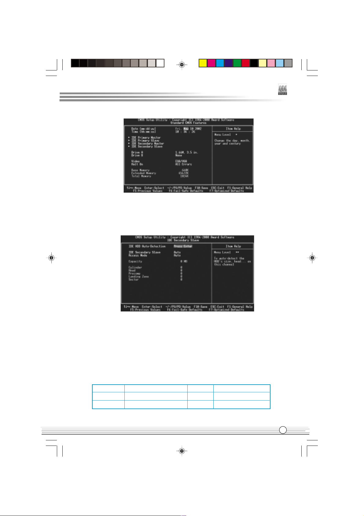
Standard CMOS Features Setup
The basic CMOS settings included in Standard CMOS Features are Date, Time, Hard Disk
Drive Types, Floppy Disk Drive Types, and VGA etc. Use the arrow keys to highlight the
item, then use the <PgUp> or <PgDn> keys to select the value desired in each item.
"
J6Aen.p65 02-7-29, 9:5514
Manual for J6A series
Page 21
Chapter 3
Figure-2 Standard CMOS Setup Menu
For the items marked, press enter, a window will pop up as shown below. You can view
detailed information or make modifications.
Figure-2-1 IDE Primary Master Setup Menu
Hard Disk
Primary Master/Primary Slave/Secondary Master/Secondary Slave
These categories identify the HDD types of 2 IDE channels installed in the computer system.
There are three choices provided for the Enhanced IDE BIOS: None, Auto, and Manual. None
means no HDD is installed or set; Auto means the system can auto-detect the hard disk when
booting up; by choosing Manual, the related information should be entered regarding the
following items. Enter the information directly from the keyboard and press < Enter>:
CYLS number of cylinders HEAD number of heads
PRECOMP write pre-compensation LANDZ landing zone
SECTOR number of sectors MODE
Manual for J6A series
J6Aen.p65 02-7-29, 9:5515
HDD access mode
15
Page 22

BIOS Description
The Award BIOS supports 3 HDD modes: CHS, LBA and LARGE.
CHS
Generic access mode in which neither the BIOS nor the IDE controller will make any transformation during accessing. The maximum number of cylinders, heads and sectors for CHS
mode are 1024,16 and 63.
If the user sets his HDD to CHS mode, the maximum accessible HDD size will be 528
megabytes even though its physical size may be greater than that.
LBA (Logical Block Addressing) mode
A new HDD accessing method to overcome the 528 Megabyte bottleneck. The number of
cylinders, heads and sectors shown in setup may not be the number physically contained
in the HDD.
During HDD accessing, the IDE controller will transform the logical address described by
sector, head and cylinder number into its own physical address inside the HDD.
LARGE mode
Some IDE HDDs contain more than 1024 cylinder without LBA support (in some cases,
users do not want LBA). The Award BIOS provides another alternative to support these
kinds of HDD.
BIOS tricks DOS (or other OS) into divising the number of cylinders is less than 1024 by dividing
it by 2. At the same time, the number of heads is multiplied by 2. A reverse transformation
process will be made inside INT13h in order to access the right HDD address.
If using Auto detect, the BIOS will automatically detect the IDE hard disk mode and set it as
one of the three modes.
Remark
To support LBA or LARGE mode of HDDs, there must be some softwares involved which
are located in Award HDD Service Routine(INT13h).It may fail to access a HDD with LBA
(LARGE) mode selected if you are running under an Operating System which replaces the
whole INT 13h.
$
J6Aen.p65 02-7-29, 9:5516
Manual for J6A series
Page 23

Chapter 3
Video
Set this field to the type of video display card installed in your system.
EGA/ VGA Enhanced Graphics Adapter / Video Graphic Array. For EGA,
VGA, SEGA, SVGA, or PGA monitor adapters.
CGA 40 Color Graphic Adapter, powering up in 40 column mode.
CGA 80 Color Graphic Adapter, powering up in 80 column mode.
MONO Monochrome adapter, including high resolution monochrome
adapters.
Halt On
This category determines whether or not the computer will stop if an error is detected
during powering up.
No errors The system boot will not stop for any errors that may be
detected.
All errors Whenever the BIOS detects a non-fatal error, the system will
stop and you will be prompted.
All, But Keyboard The system boot will not stop for a keyboard error; but it will
stop for all other errors.
All, But Diskette The system boot will not stop for a disk error; but it will stop
for all other errors.
All, But Disk/Key The system boot will not stop for a keyboard or disk error, but it
will stop for all other errors.
Memory
This is a Display-Only Category, determined by POST (Power On Self Test) of the BIOS.
Base Memory The POST of the BIOS will determine the amount of base
(or conventional) memory installed in the system.
Extended Memory The BIOS determines how much extended memory is
presented during the POST.
Total Memory Total memory of the system
Manual for J6A series
J6Aen.p65 02-7-29, 9:5517
17
Page 24

BIOS Description
Advanced BIOS Features Setup
Figure-3 BIOS Features Setup Menu
The following indicates the options for each item and describes their meaning.
Item Option Description
#"QDI BootEasy Enabled PC boots in rapid speed, without any redundant
Feature waiting for the displaying of starting OS.
Disabled PC boots in the legacy BIOS way.
#"ChipAway Virus Enabled Allows you to choose the virus warning feature
on Guard for IDE hard disk boot sector protection. If this
function is enabled and someone attempt to write
data into this area, BIOS will show a warning
message on screen and alarm beep.
Disabled Invalidates this function.
# CPU Enabled Enables CPU internal cache.
Internal Cache Disabled Disables CPU internal cache.
# External Cache Enabled Enables CPU external cache.
Disabled Disables CPU external cache.
#" CPU L2 Cache Enabled Enables CPU L2 Cache ECC function.
ECC Checking Disabled Disables CPU L2 Cache ECC function.
# Processor Enabled Processor Number can be readable.
Number Feature Disabled Processor Number can be unreadable.
&
J6Aen.p65 02-7-29, 9:5518
Manual for J6A series
Page 25

Chapter 3
# Quick Power Enabled Enable quick POST. BIOS will shorten or skip
On Self Test some check items during POST to speed up POST
after you power on the computer.
Disabled Normal POST
# First (Second, Disabled Selects Your Boot Device Priority. It could be
Third) Boot ...... Disabled, Floppy, LS120, ZIP100, HDD-0, HDD-1,
Device Floppy HDD-2, HDD-3, SCSI, CDROM, LAN, USB-
FDD, USB-ZIP, USB-CDROM, USB-HDD.
# Boot Other Enabled Boot other Device enabled.
Device Disabled Boot other Device disabled.
# Swap Floppy Enabled Exchanges the assignment of A&B floppy drives.
Drive Disabled The assignments of A&B floppy drives are normal.
# Boot Up On Keypad is used as number keys.
Numlock Status Off Keypad is used as arrow keys.
# Gate A20 Normal The A20 signal is controlled by the keyboard
Option controller or chipset hardware.
Fast The A20 signal is controlled by Port92.
# Security Option System Selects whether the password is required every
Setup time the system boots or only when you enter setup.
# OS Select For Non-OS2 If your operating system is not OS/2, please select
DRAM>64MB this item.
OS2 If system DRAM is more than 64MB and the operating
system is OS/2, please select this item.
# HDD S.M.A.R.T Enabled Enables S.M.A.R.T hard disk support.
Capability Disabled Invalidates this function.
# Report NO FDD Yes Report NO Floppy Disk Drive for WIN 95 to
for WIN 95 release IRQ6.
No Do not report No Floppy Disk Drive for WIN 95.
# Video BIOS Enabled Video BIOS will be copied to RAM. Video Shadow
Shadow will increase the video speed.
Disabled Invalidates this function.
# C8000-CBFFF Enabled Optional ROM will be copied to RAM by 16K bytes
Shadow: per unit.
...........
DC000-DFFFF
Shadow: Disabled Invalidates this function.
Manual for J6A series
J6Aen.p65 02-7-29, 9:5519
19
Page 26

BIOS Description
# Delay For HDD 0~3 Sets the pre-delay time for hard disk to be
(Secs): accessed by the system.
# Show Bootup Enabled The logo will be shown when system boots up.
Logo Disabled The logo will not be shown when system boots up.
# Flash Write Enabled This option is for protecting the system BIOS from
Protect being attacked by severe virus such as CIH.
Disables you to upgrade the BIOS.
Disabled Enables you to upgrade the BIOS.
J6Aen.p65 02-7-29, 9:5520
Manual for J6A series
Page 27

Chapter 3
Advanced Chipset Features Setup
Figure-4 Advanced Chipset Features Setup Menu
The following indicates the options for each item and describes their meaning.
Item Option Description
# Close Empty Enabled Closes empty DIMM or PCI clock to reduce EMI.
DIMM/PCI Clk Disabled Does not close empty DIMM or PCI clock.
# Display Device CRT+TV Enable CRT and TV display together.
CRT Enable CRT display only.
TV Enable TV display only.
# Bank 0/1 SDRAM 8/10ns These items are of selected DRAM read/write
DRAM Timing Normal/Medium timing. Default setting is recommended.
Fast/Turbo
# SDRAM Cycle 2/3 Defines the CLT timing parameter of SDRAM
Length Auto expressed in 66MHz clocks.
Latency Time = 2 clocks, Latency Time = 3 clocks
#"DRAM Clock Host Clk DRAM clock is same as host clock.
Hclk-33M DRAM clock is slower than host clock by 33MHz.
#"Memory Hole 15M~16M Memory Hole at 15-16M is reserved for expanded
ISA card.
Disabled Does not set this memory hole.
#"P2C/C2P Enabled Enables P2C/C2P concurrency.
Concurrency Disabled Disables P2C/C2P concurrency.
# Fast R-W Turn Enabled Enables Fast R-W Turn Around.
Around Disabled Disables Fast R-W Turn Around.
Manual for J6A series
21
J6Aen.p65 02-7-29, 9:5521
Page 28

BIOS Description
#"System BIOS Enabled Besides conventional memory, system BIOS area
Cacheable is also cacheable.
Disabled System BIOS area is not cacheable.
#"Video RAM Enabled Besides conventional memory, video RAM is also
Cacheable cacheable.
Disabled Video RAM area is not cacheable.
# Frame Buffer Size 2M~8M Sets share memory of onboard AGP.
#" AGP Aperture Size 4~128M Sets the effective size of the Graphics Aperture
to be used in the particular PAC Configuration.
# Onchip USB Enabled Enables the onchip USB controller.
Disabled Disables the onchip USB controller.
#"USB Keyboard Enabled USB keyboard support is enabled.
Support Disabled USB keyboard support is disabled.
# Onchip Sound Auto Enables AC97 function.
Disable Disables AC97 function.
# CPU"to PCI Write Enabled Enables CPU to PCI Write Buffer.
Buffer Disabled Disables CPU to PCI Write Buffer.
#" PCI Dynamic Enabled Enables PCI Dynamic Bursting.
Bursting Disabled Disables PCI Dynamic Bursting.
#" PCI Master 0 WS Enabled Enables PCI Master 0 WS Write.
Write Disabled Disables PCI Master0 WS Write.
# PCI Delay Enabled Enables PCI Delay Transaction.
Transaction Disabled Disables PCI Delay Transaction.
# PCI#2 Access #1 Enabled Enables PCI#2 Access #1 Retry.
Retry Disabled Disables PCI#2 Access #1 Retry.
#" AGP Master 1 WS Enabled Enables AGP Master 1 WS Write.
Write Disabled Disables AGP Master 1 WS Write.
#" AGP Master 1 WS Enabled Enables AGP Master 1 WS Read.
Read Disabled Disables AGP Master 1 WS Read.
J6Aen.p65 02-7-29, 9:5522
Manual for J6A series
Page 29

Chapter 3
Power Management Setup
Figure-5 Power Management Setup Menu
The following indicates the options for each item and describes their meaning.
Item Option Description
# ACPI function Enabled Validates ACPI function.
Disabled Invalidates ACPI function.
# Power User Define Users can configure their own Power Management
Management Timer.
Min Saving Pre - defined timer values are used. All timers are
in their MAX values.
Max Saving Pre - defined timer values are used. All timers are in
their MIN values.
# HDD Power 1Min~15Min Defines the continuous HDD idle time before the
Down HDD entering power saving mode (motor off).
Disable Invalidates this function.
# Doze Mode 1Min~1Hour Defines the continuous idle time before the system
entering Doze mode.
Disable Invalidates this function.
# Suspend Mode 1Min~1Hour Defines the continuous idle time before the system
entering suspend mode.
Disable Invalidates this function.
# PM Control by NO System BIOS will ignore APM when Power
APM Management is enabled.
Yes System BIOS will wait for APMs prompt before
entering any PM mode e.g. Standby or Suspend.
# Video Off Suspend -> Off Screen blanks after the system enters suspend
Option mode.
All Modes -> Off Screen blanks after the system enters all modes.
Always On Screen is always on.
Manual for J6A series
J6Aen.p65 02-7-29, 9:5523
23
Page 30

BIOS Description
# Video Off Blank Screen The system BIOS will only blank off the screen
Method when disabling video.
V / H SYNC + In addition to Blank Screen, BIOS will also turn
Blank off the V-SYNC & H - SYNC signals from VGA
cards to monitor.
DPMS This function is enabled only for the VGA card
Support supporting DPMS.
# MODEM Use IRQ 3,4,5,7,9, Special Wake-up event for Modem.
10,11
NA This function is not applied.
# Soft-off by Instant-off The system will power off immediately once the
PWRBTN power button is pressed.
Delay 4 Sec The system will not power off until the power
button has been pressed continuously for more
than 4 seconds.
# State After Auto The system remains former state/Off/On when the
Power Failure Off,On AC power supply resumes.
#"Wake Up Events Press Enter Sets the following items.
# VGA On VGA active reloads global timer.
Off VGA active has no influence to global timer.
#"LPT&COM LPT, COM Sets the options of these items to reload global
LPT/COM timer.
None LPT&COM active has no influence to global timer.
#"HDD&FDD On HDD&FDD active reloads global timer.
Off HDD&FDD active has no influence to global timer.
# PCI Master On PCI Master active reloads global timer.
Off PCI Master active has no influence to global timer.
# Power On by PCI Enabled Enables to wake up by PCI card.
Card Disabled Disables to wake up by PCI card.
# RTC Alarm Enabled RTC alarm can be used to generate a wake event
Resume to power up the system which is in power-off
status. You can set any date or any time to
power up the system.
Disabled RTC has no alarm function.
"
J6Aen.p65 02-7-29, 9:5524
Manual for J6A series
Page 31

#"Date( of Month ) Sets the date of RTC.
#"Resume Time Sets the resume time of RTC.
# IRQs Activity Press Enter Reloads global timer.
Monitoring
# Primary INTR On Allows wake-up from IRQ.
Off Does not allow wake-up from IRQ.
#" IRQ3~IRQ15 Enabled Enables IRQx to wake up.
Disabled Disables IRQx to wake up.
Chapter 3
J6Aen.p65 02-7-29, 9:5525
Manual for J6A series
25
Page 32

BIOS Description
PNP/PCI Configurations Setup
Figure-6 PNP/PCI Configurations Setup Menu
The following indicates the options for each item and describes their meaning.
Item Option Description
#"PNP OS Installed Yes Device resources assigned by PnP OS.
No Device resources assigned by BIOS.
# Reset Configuration Enabled The system BIOS will reset configuration data
Data once then automatically set this item as disabled.
Disabled Disables this function.
# Resources Manual Assigns the system resources ( IRQ and DMA)
Controlled By manually .
Auto(ESCD) Assigns system resources (IRQ and DMA) auto-
matically by BIOS.
# Assign IRQ For Enabled Assigns the needed IRQ for the VGA card.
VGA Disabled Does not assign an IRQ for the VGA card, in
order to release the IRQ.
# Assign IRQ For Enabled Assigns an IRQ to USB device.
USB Disabled Does not assign an IRQ to USB device.
$
J6Aen.p65 02-7-29, 9:5526
Manual for J6A series
Page 33

Chapter 3
Integrated Peripherals
Figure-7 Integrated Peripherals Menu
The following indicates the options for each item and describes their meaning.
Item Option Description
# OnChip IDE Enabled Enables OnChip IDE First/Second Channel.
Channel 0/1 Disabled Disables OnChip IDE First/Second Channel.
# IDE Prefetch Mode Enabled Enables IDE Prefetch Mode.
Disabled Disables IDE Prefetch Mode.
# Primary/Secondary Mode 0 ~ 4 Defines the IDE primary/secondary master/slave
Master/Slave PIO PIO mode.
Auto The IDE PIO mode is defined by auto -detection.
# Primary/Secondary Auto Ultra DMA mode will be enabled if an ultra DMA
Master/Slave UDMA device is detected.
Disable Disables this function.
# Init Display First PCI SLOT Initializes the PCI VGA first. If a PCI VGA card
and anAGP card are installed together in the
system, the one initialized first functions.
AGP Initializes the AGP first.
# IDE HDD Block Enabled Allows IDE HDD to read/write several sectors
Mode once.
Disabled IDE HDD only reads/writes a sector once.
# Onboard LAN Enabled Onboard LAN function is enabled.
Disabled Onboard LAN function is disabled.
# Onboard FDD Enabled Onboard floppy drive controller is enabled.
Controller Disabled Onboard floppy drive controller is disabled.
Manual for J6A series
27
J6Aen.p65 02-7-29, 9:5527
Page 34

BIOS Description
# Onboard Serial 3F8/IRQ4 Defines the onboard serial port address and required
Port 1/2 2F8/IRQ3 interrupt number.
3E8/IRQ4
2E8/IRQ3
Auto Onboard serial port address and IRQ are auto-
matically assigned
Disabled Onboard serial port is disabled.
#" UART 2 Mode Standard Defines Serial Port 2 as standard serial port.
HPSIR Supports IrDA mode.
ASKIR Supports SHARP ASK-IR protocol with maximum
baud rate up to 57600bps.
# Onboard Parallel 378/IRQ7 Defines onboard parallel port address and IRQ
Port 278/IRQ5 channel.
3BC/IRQ7
Disabled Onboard parallel port is disabled.
# Onboard Parallel Normal Defines the parallel port mode as Standard Parallel
Mode EPP Port (Normal), Enhanced Parallel Port (EPP),
ECP/EPP or Extended Capabilities Port (ECP).
ECP
# ECP Mode Use 1, 3 Sets DMA for ECP mode use.
DMA
#"Parallel Port EPP EPP1.7 Sets parallel port EPP type.
Type EPP1.9
# Onboard Legacy Enabled Enables onboard legacy audio, the following item
Audio to be set.
Disabled Disables onboard legacy audio.
# Sound Blaster Enabled Enables Sound Blaster.
Disabled Disables Sound Blaster.
# SB I/O Base 220H/240H Defines SB I/O Base Address.
Address 260H/280H
# SB IRQ Select IRQ5~IRQ10 Selects SB IRQ .
#" SB DMA Select DMA0~DMA3 Selects SB DMA.
#" MPU-401 Enabled Enables MPU-401
Disabled Disables MPU-401
#" MPU-401 I/O 300-303H~ Defines MPU-401 I/O address.
Address 330-333H
#" Game port Enabled Enables game port.
(200-207H) Disabled Disables game port.
&
J6Aen.p65 02-7-29, 9:5528
Manual for J6A series
Page 35

PC Health Status
Figure-8 PC Health Status Menu
The following describes the meaning of each item.
Item Current Description
Data Shown
Chapter 3
# CPU Warning 50
0
C/1220F An alarm will beep when the CPU
Temperature 530C/1270F temperature reaches the previous setting,
560C/1330F 50
600C/1400F 60
630C/1450F 70
C/122F, 53C/127F, 56C/133F,
C/140F, 63C/145F, 66C/151F,
C/158F.
660C/1510F
700C/1580F
Disable No alarm beep.
# Current CPU/System Temp Temperature of the CPU/System.
# Current CHSFAN Speed Speed of fan(RPM:Revolution Per Minute)
connected to the fan header CHSFAN. Fan
speed value is based on an assumption that
tachometer signal is two pulses per revolution.
In other cases, you should regard it relatively.
Manual for J6A series
29
J6Aen.p65 02-7-29, 9:5529
Page 36

BIOS Description
#"Vcore Displays current Voltage values including all
2.5V significant voltages of the mainboard. +3.3V,
3.3V +12V and 5V are voltages from the
5V ATX power supply. Vcore Voltage is the
12V CPU core voltage from the onboard switching
power supply.
!
J6Aen.p65 02-7-29, 9:5530
Manual for J6A series
Page 37

Chapter 3
Supervisor/ User Password
When this function is selected, the following message appears at the center of the screen
to assist you in creating a password.
ENTER PASSWORD
Type the password, up to eight characters, and press <Enter>. The password typed now
will clear any previously entered password from CMOS memory. You will be asked to
confirm the password. Type the password again and press <Enter>. You may also press
<Esc> to abort the selection.
To disable password, just press <Enter> when you are prompted to enter password. A
message will confirm the password being disabled. Once the password is disabled, the
system will boot and you can enter BIOS Setup freely.
PASSWORD DISABLED
If you have selected System in Security Option of Advanced BIOS Features menu,
you will be prompted for the password every time the system reboots or any time you try to
enter BIOS Setup.
If you have selected Setup in Security Option of Advanced BIOS Features menu, you will
be prompted for the password only when you enter BIOS Setup.
Supervisor Password has higher priority than User Password. You can use Supervisor
Password when booting the system or entering CMOS Setup to modify all settings. Also
you can use User Password when booting the system or entering CMOS Setup but can
not modify any setting if Supervisor Password is enabled.
Boot with BIOS defaults
If you have made all the changes to CMOS values and the system can not boot with the
CMOS values selected in setup, clear CMOS after power-down, then power on again.
System will boot with BIOS default settings.
Manual for J6A series
J6Aen.p65 02-7-29, 9:5531
31
Page 38

Appendix
QDI Utility CD
A QDI Utility CD is supplied with this mainboard, The contents contained in it are showed as
below:
1. Driver Install
Using this choice, you can install all the drivers for your motherboard easily. You
should install the drivers in order, and you need to restart your computer after all
the drivers are installed.
A. Chipset Software B. VGA Driver
C. Network Driver D. Audio Driver
E. DirectX
2. Accessory
A: Norton AntiVirus 2002
B: QflashV1. 0
3. Browse CD
You could read all the contents contained in this CD, including Utility and Documents.
The files included in Utility are:
A. Awdflash.exe B. Lf.exe C. Cblogo.exe
The files included in Documents are:
A. Adobe Acrobat Reader V5.0
B. J6A-french.doc, J6A-Spanish.doc etc.
Norton AntiVirus
When you install Norton AntiVirus and accept options, your computer is safe. Norton
AntiVirus automatically checks boot records for viruses at system startup, checks programs for viruses at the time you use them, scans all local hard drives for viruses once per
week, and monitors your computer for any activity that might indicate the work of a virus in
action. It also scans files you download from the internet and checks floppy disks for boot
viruses when you use them. The list below shows the most important tasks Norton AntiVirus
helps you perform: scan for viruses on your computer; remove viruses from your computer;
update your virus protection with LiveUpdate; quarantine an infected file.
You can go to the Symantec Web site to view an online tutorial:
http://www.symantec.com/techsupp/tutorial
!
J6Aen.p65 02-7-29, 9:5532
Manual for J6A series
Page 39

Appendix
LogoEasy IILogoEasy II
LogoEasy II
LogoEasy IILogoEasy II
Thank you for using QDI upgraded innovation--- LogoEasy II, which is completely
compatible with LOGOEASY. LOGOEASY II can be easily operated in a Windows
environment, following in steps with the trend. It has added the functions of supporting JPEG images and true color display of 64K and 16M colors with regard to JPEGformat graphics files and the high-precision display equipment, which are now widely
used.
LOGOEASY II supports the high-resolution 640x480 or 800x600 image display and
full-screen, top right corner or bottom right corner display. It also supports simultaneous display of logo and sign-on message of the BIOS testing system. LOGOEASY
II is a tool that can be operated in multi-platforms to refresh and change LOGO graphics including DOS, WINDOWS 9X, WINDOWS NT, WINDOWS ME and WINDOWS XP.
In particular, the tools under the interface of WINDOWS are simple and easy to operate.
It teaches you by taking your hand how to change LOGO.
ITEM LogoEasy II LogoEasy
$ ------ Support x ------- Not Support
When you power on or reset your system,
the picture shown below will be displayed
on the screen.
You can use LogoEasy II to replace it by
any other logo which you want.
We provide two Utilities in the QDI Driver CD
, which bring user the following two means
to select:
J6Aen.p65 02-7-29, 9:5533
Manual for J6A series
33
Page 40

A. Using CBLOGO.EXE Utility (Under DOS ):
1.Copy CBLOGO.EXEand AWDFLASH.EXE from the directory \Utility located on
QDI Driver CD to your hard disk.
2. Get the BIOS file from AWDFLASH.EXE or Download the BIOS file from the
Website (http://www.qdigrp.com) and copy the BIOS file(xxxxxx.bin) to your hard
disk.
3. Boot the system into DOS environment, Put your favor picture into BIOS file by
CBLOGO.EXE command. For example: CBLOGO.EXE xxxxxx.bin myphoto.bmp
4. Flash the BIOS to motherboard by AWDFLASH.EXE. For example: AWDFLASH
xxxxxx.bin
B. Using QFlash (Under Windows ):
1. Download the QFlash Utility from the Website (http://www.qdigrp.com) or get it
from QDI Driver CD.
2. Run QFlash program step by step,following the directions until complete it .
3. Reboot the system, you can see the new picture displayed on the screen.
NOTE:
If you require more parameters information concerning CBLOGO.EXE, please
refer to the online help. If you dont prefer the logo displayed on the
screen during bootup, set the Show Bootup Logo option as Disabled in
CMOS Setup.
* We reserve the right of modifying the default full-logo of QDI without
further notification.
BIOS-ProtectEasyBIOS-ProtectEasy
BIOS-ProtectEasy
BIOS-ProtectEasyBIOS-ProtectEasy
The BIOS of the mainboard is contained inside the Flash ROM. Severe viruses such as
CIH virus are so dangerous that it may overwrite the BIOS of the mainboard. If the BIOS
has been damaged, the system will be unable to boot. We provide the following solution
which protects the system BIOS from being attacked by such viruses.
There are two choices which implements this function.
1. Set the jumper (JAV) as closed, the BIOS can not be overwritten.
2. Set the jumper (JAV) as opened, meanwhile set Flash Write Protect as Enabled in
CMOS Setup. In this way, the BIOS can not be overwritten, but the DMI information
can be updated.
!"
J6Aen.p65 02-7-29, 9:5534
Manual for J6A series
Page 41

Appendix
RecoveryEasyRecoveryEasy
RecoveryEasy
RecoveryEasyRecoveryEasy
Introduction:
RecoveryEasy, the latest QDI innovation, is able to protect the system from being destroyed,
by creating a so-called mirror partition for a current hard disk partition and backuping all
the data to the mirror area. This ideal utility provides disk partition, disk data backup/recovery,
CMOS settings backup/recovery and multi-boot functions. RecoveryEasy is also able to
prevent the system from being attacked by different kinds of boot virus or other severe
virus such as CIH. In case the system is ruined either by mistake or virus, the system can be
recovered from the mirror partition. It applies the build-in BIOS technology that does not
occupy either the hard disk space or the system memory. Its the best choice for both
corporations and PC users.
Operation Process:
There are two hotkeys Ctrl+Bksp and F12 for RecoveryEasy to enter Partition and
Recovery user interfaces accordingly during BIOS booting up. If two or more hard disks
are installed, use F5 key to choose the hard disk.
1. Partition Interface (see figure-1)
Users can create and delete partitions/mirror partitions, activate partitions, and uninstall
RecoveryEasy in Partition User Interface.
figure-1 Partition Interface
1.0 Install RecoveryEasy for the first time
a. The utility checks the previous disk partition at first, and displays the status of the first
four partitions. If there are more than four disk partitions, users will be asked to delete
the redundant disk partitions, since only four partitions that can be activated are
allowed to exist. However, if therere only four or fewer partitions, users can follow
the system prompt and choose to install RecoveryEasy based on the previous disk
partitions. In this way, the original extension partitions will be changed to normal ones,
and probably the sequence of the partitions will be changed also, but the contents
contained in each partition will remain the same.
Manual for J6A series
J6Aen.p65 02-7-29, 9:5535
35
Page 42

b. If choosing to install RecoveryEasy on an absolutely clear disk, the utility will delete all
the previous partitions.
c. The password is set as default setting qdiqdi after installing RecoveryEasy.
1.1 CREATE PAR
Function : Creates a new partition.
Limitation : When no disk space remains or 4 partitions already exist, this button is
disabled.
Steps : After pressing the CREATE PAR button.
a. The system will prompt whether users want to create a mirror partition for it or not.
b. If answering Y, input the new partition size in Megabyte. Notice that the maximum
partition size that can be assigned is half of the left disk space, which is also displayed
in the status line. Another half is for the mirror partition. If answering N, the whole disk
space left can be assigned. See figure-2.
figure-2 Create Partition
Note:
a. The system will prompt Insert system floppy, then reset when the first partition on the
first hard disk is created.
b. After using DOS6.xx boot disk to format C partition, the system should be reset in order
to access the partition.
c. In Windows system 1,048,576 bytes equal 1 Megabyte, while in RecoveryEasy 1,000,
000 bytes equal 1 Megabyte, therefore a smaller size will be displayed in Windows
system compared with the size displayed in RecoveryEasy.
1.2 DELETE PAR
Function : Deletes the last partition and its mirror partition.
Limitation : When no partition exists, this button is disabled.
Steps : After choosing this function, only the final partition can be deleted in order to
keep the continuous disk space. If the warning message is confirmed, the partition will
be deleted. By pressing N or ESC key, the system quits.
!$
J6Aen.p65 02-7-29, 9:5536
Manual for J6A series
Page 43

Appendix
1.3 ACTIVE PAR
Function : Implements multi-boot function by activating one of the partitions.
Limitation : When no partition exists, this button is disabled.
Steps : If therere two or more partitions, choose one of them by pressing F5 key.
Note : After setting active partition, a letter A will be shown in front of this partition.
1.4 CREATE MIR
Function : Adds mirror partition for the disk partition that has no mirror.
Limitation : This function should be performed by order, for example, from partition 1 to
4. If no disk space remains or the last partition has its mirror partition already, this button
is disabled.
Steps : After pressing the CREATE MIR button, use F5 key to choose the partiti to
create mirror. The partition of which the size is bigger than the left disk space will be
ignored.
1.5 DELETE MIR
Function : Deletes the mirror partition.
Limitation : If there is no mirror partition, this button is disabled. This function should be
performed in reverse order, for example, from partition 4 to 1.
Steps : After pressing the DELETE MIR button, only the final mirror partition can be
deleted in order to keep the continuous disk space. If the warning message is confirmed,
the mirror partition will be deleted. By pressing N or ESC key, the system quits.
1.6 UNINST SFW
Function : Uninstall RecoveryEasy.
Limitation : None.
Steps : After pressing the UNINST SFW button and the warning message is confirmed,
RecoveryEasy will be uninstalled. By answering N, the system quits.
Note : After RecoveryEasy is uninstalled, all the mirror areas have been disconnected
with the relate partitions. If no partition is deleted or changed in size, or no other partition
is created, users have chance to Recover existing RecoveryEasy settings when next
time entering RecoveryEasy partition interface, meanwhile the password will be set as
default setting qdiqdi.
1.7 OTHERS
F12 : Switches to Recovery User Interface.
ESC : Exits from the Partition User Interface. If users made some mistakes, for example,
wrongly delete a partition, do not press the ESC key, press the reset button on your
system at once, in this way users can save their system.
Manual for J6A series
J6Aen.p65 02-7-29, 9:5537
37
Page 44

F5:
a. When two or more than two hard disks are installed on the system, use F5 key to
choose the hard disk. Every time users use F5 key to switch the hard disk, the
operation result for the previous hard disk is saved. When processing a certain hard
disk, F5 key can be used to choose the partition.
b. In addition, when two or more than two hard disks are installed, the sign of partitions
will be changed from C, D, E, F to 1, 2, 3, 4 accordingly.
2. Recovery Interface (see figure-3)
Users can backup the partition to its mirror area, and recover the partition from its mirror
area from Recovery User Interface. This interface also provides users with CMOS
settings backup or recovery, and changing password functions.
figure-3 Recovery User Interface
2.1 BACKUP PAR
Function : Backups the content of the partition to its mirror area.
Limitation : If no mirror partition exists, this button is disabled.
Steps :
a. Use F5 key to choose the partition with mirror area existed.
b. If the partition chosen has been backuped before, a warning message will be shown,
and the time when last backup was done will be displayed in the status line. After
confirming the warning message, the system performs the backup. By pressing N or
ESC key, the system quits.
2.2 RE-CVR PAR
Function : Recovers the content from the mirror area to the relate partition.
Limitation : If users didnt backup any partitions before, this button is disabled.
Steps:
a. Use F5 key to choose the backuped partition.
b. The time when the latest backup was done will be displayed in the status line. After
confirming the warning message, the system performs the content recovery. By
pressing N or ESC key, the system quits.
!&
J6Aen.p65 02-7-29, 9:5538
Manual for J6A series
Page 45

Appendix
Note:
a. During the process of partition backup or recovery, a guage will be shown as below,
the backup or recovery speed is about 4-5Mbyte/s. See figure-4.
figure-4 Backup Partition
b. If a disk I/O error occurs during the process of partition backup or recovery, this
means theres physical damage on the hard disk, however users can ignore it and
continue the process.
2.3 ATTRIB PAR
Function : Allows users to modify the properties of the partition (eg. FAT16 -> FAT32)
after entering OS.
Limitation : None.
Steps : After pressing this button, turn on/off the switch.
Note:
a. The switch resets to the default setting disable every time the system reboots.
b. In order to implement this function, users need to enable the switch when installing the
OS or modifying the partition properties. Please note: Do not create or delete partitions or
change the partition size when modifying the partition properties.
2.4 BACKUP CMS
Function : Backups all CMOS settings.
Limitation : None.
Steps : After choosing this function, the current CMOS settings will be saved.
2.5 RE-CVR CMS
Function : Recovers all CMOS settings.
Limitation : None.
Steps : After choosing this function, the latest backup of the CMOS settings will be
recovered. The system needs reboot in order to validate the new CMOS settings.
Note : If users have never backuped the CMOS settings, a wrong message will be
shown after choosing this function.
Manual for J6A series
J6Aen.p65 02-7-29, 9:5539
39
Page 46

2.6 CHANGE PWD
Function : Changes the password to enter RecoveryEasy Partition or Recovery User
Interface.
Limitation : None.
Steps : Follow the system prompt, input the password no more than 6 characters twice.
To delete the password, follow the system prompt and press the Enter key twice.
Note:
a. The password should be no more than 6 characters, only digital and alphabetic letters
are valid.
b. Once the password is enabled, users will be asked to input the password every time
they try to enter the RecoveryEasy user interfaces, and up to 3 times try is permitted.
2.7 Others
Ctrl+Bksp : Switches to Partition User Interface.
ESC : Exits from the Partition User Interface.
F5 : When two or more than two hard disks are installed on the system, use F5 key to
choose the hard disk. When processing a certain hard disk, F5 key can be used to choose
the partition.
FAQ:
1. What does RecoveryEasy do?
RecoveryEasy creates a so-called mirror partition with same size for the hard disk
partition on the same hard disk, and then completely backups all the data sector by sector
to the mirror area. This mirror partition is reserved to OS. When the OS ruins either by
mistakes or virus, users can recover the partition from its mirror.
2. Does RecoveryEasy occupy the system resources?
Although some hard disk data protection applications can automatically protect the disk
data in runtime, it lowers the system performance. Unlike these applications RecoveryEasy
need users to backup or restore data manually when needed, but it DOES NOT lower the
system performance when the system is running. It does not occupy either hard disk
space or system memory, additional floppy disk or ISA/PCI cards are unnecessary.
3. RecoveryEasy utilizes Build-in BIOS skill, what is build-in BIOS?
R ecoveryEasy build-in BIOS means all functions of RecoveryEasy including creating partition,
backuping and restoring partition are built in BIOS. Users just need to down load the latest
BIOS from our Website (http://www.qdigrp.com) when wanting to upgrade (Its free!).
4. Are there any hard disk limitations of RecoveryEasy?
RecoveryEasy supports all kinds of current IDE hard disks and has no limitation on the
hard disk capacity. RecoveryEasy can not provide its function for some special hard
disk types such as SCSI, but it will not affect their usage.
"
J6Aen.p65 02-7-29, 9:5540
Manual for J6A series
Page 47

Appendix
5. Are there any OS limitations of RecoveryEasy?
RecoveryEasy supports current operating systems such as DOS, Windows 95/98.
However in Windows NT, Windows 2000, Unix and OS2 systems, users should notice
that the disk tools bundled in the OS could change the mirror partition. On the other hand,
since users can create partition with RecoveryEasy, it is unnecessary to use other disk
tools.
6. Why does the remainder size plus partitions size not match the total size
shown in RecoveryEasy sometimes?
When the location of partitions is not continuous, the above problem exists.
7. Are there any other disk partition tools that can modify the partition table made
by RecoveryEasy?
RecoveryEasy provides a write-protect function, so the disk tools such as Fdisk, Partition
Magic, BootMenu, SmartDisk and BootStar can not modify the partition table created by
RecoveryEasy. Some of the applications even terminate during operation. However the
disk tools bundled in the OS such as Windows NT, Windows 2000, Unix and OS2 could
change the mirror partition.
8. Why does it happen that a prompt installation can not continue pops up
when installing Windows98 or a yellow exclamation mark shown beside IDE
device in system properties?
During Windows 98 installation, the installation program will write to MBR (Master Boot
Record) which is protected by RecoveryEasy, therefore the installation will be terminated.
To avoid this problem, a ATTRIB PAR button is provided in Recovery User Interface.
Enable this switch before installing Windows 98, then the installation will be success
fully completed. In order to remove the yellow question mark before IDE devices in
Device Manager, enable this switch once more after system reboot.
9. Why does the converting of FAT16->FAT32 in PQ Magic go wrong?
MBR will be accessed when converting FAT16 to FAT32 with PQ Magic, which is pro
te ct ed by RecoveryEasy, therefore the conversion will be invalidate. Enabling the ATTRIB
PAR switch from Recovery User Interface before converting can avoid this problem. Its
the same situation as FAT32 Converter provided in Windows 98.
10. What if partitions be wrongly deleted in RecoveryEasy?
If users delete a partition in RecoveryEasy by mistake, they can save it by pressing the
Reset button on their system at once. Do not press the ESC key to quit RecoveryEasy,
this will save the change. Do not try to create the partition again, since creating partition
will clear all the content of the partition.
Manual for J6A series
J6Aen.p65 02-7-29, 9:5541
41
Page 48

11. What is multi-boot?
RecoveryEasy can implement the multi-boot function by activating different partition.
For example on the hard disk, partition C contains DOS, partition D contains Windows
95 version, partition E contains Windows 98 version, when activating partition C in
RecoveryEasy, the system enters DOS, when activating partition E, the system enters
Windows 98 version. At the same time, the sequence of the partitions is adjusted
accordingly, partition E becomes C:, partition C becomes D: and partition D becomes E:.
This function is the same as that of fdisk.exe, but the system needs reboot in order to
make the change validate for fdisk.exe.
12. What if computer accidentally power off when backuping (recovering)?
The partition should be completely backuped or recovered. If the computer acciden
tally powers off, the partition should be backuped or recovered once again.
13. What if users lose the password?
To make sure the security, the password is saved in the hard disk. Its very impor tant for users to remember the password. If forgetting the password, contact
us, clearing CMOS is useless.
14. Does RecoveryEasy protect hard disk against CIH?
RecoveryEasy can strongly protect the hard disk from boot-virus, as well as the
attack of CIH. If the system is attacked by CIH, RecoveryEasy will automatically
recover the MBR and each partition boot record before system boots up, and try to
recover the FAT. In this way the system can basically boot up, then users can use
some anti-virus application to kill the virus. However this depends on how CIH virus
th
affects the system. CIH normally outbreaks on 26
every month, if the system can
not boot up that day, power off the computer instantly, and use the second safe way
to recover the system, that is, recover the partition from its mirror area from Recov
ery User Interface. Remember to create a mirror partition and backup before virus
attacks the system.
"
J6Aen.p65 02-7-29, 9:5542
Manual for J6A series
Page 49

Appendix
BootEasyBootEasy
BootEasy
BootEasyBootEasy
BootEasy technology enormously improves the long BOOT process time of computers.
Reducing the wait time every user has to suffer when starting their computer. BIOS without
BootEasy has to perform many routines every time when the system starts, such as
checking system core of the computer and initializing system peripherals. Now with the
BootEasy, BIOS will not run these repetitive Processes any longer , PC can boot-up without
any redundant waiting for the displaying of starting OS. BootEasy is quite easy to use ,
choose the right option in CMOS SETUP, ( refer to QDI Innovation features) it can be easily
booted quickly. BootEasy save all the information when PC first normally boot-up, and it
restores all the parameters for the system and thus let the PC boot freely and rapidly.
Note:
1. Under the following conditions, PC will boot-up in normal way.
(1) PC boot-up for the first times after set option as Enabled.
(2) the system information saved by BIOS was damaged.
(3) PC fail to boot-up continually over three times.
Setting the jumper JAV as open if you encounter the above conditions.
2. Dont power off or reset system while BootEasy initializing.
3. set QDI BootEasy Feature as Disabled before you replace system equipment.
set QDI BootEasy Feature as Enabled after you accomplished replacing.
Manual for J6A series
J6Aen.p65 02-7-29, 9:5543
43
Page 50

QDI BootEasy(German)
BootEasy ist eine Neuentwicklung von QDI, die neue Innovation der QDI Easy
Technologien.
BootEasy Setup Menu
Mit der BootEasy- Technologie Technik wird der Bootvorgang nur noch vier bis fünf
Sekunden in Anspruch nehmen, bis das Betriebssystem geladen wird. Der Grund für die
lange Warterei liegt in den Routine-Abfragen, die das BIOS bei jedem Start abarbeitet. So
wird beispielsweise jedes Mal die Taktfrequenz des Prozessors geprüft oder
angeschlossene Geräte aktiviert.
Die BootEasy-Technik prüft diese Punkte nur beim erstmaligen Start des Rechners und
speichert die Ergebnisse in einem Flash ROM. Beim nächsten Start ruft das System
lediglich diese Informationen aus dem Speicher ab und kann so innerhalb von wenigen
Sekunden den Boot-Prozess abschließen.
Bei Änderungen am System, beispielsweise nach dem Einbau eines neuen Prozessors,
muss deshalb zuvor die BootEasy-Funktion deaktiviert werden, beim nächsten Start
werden die neuen Informationen dann erneut abgespeichert.
Falls Fehler im Flash ROM den Bootvorgang behindern, versucht das System drei Mal
den Rechner hochzufahren, bei Misserfolg schaltet
es auf die althergebrachte Art zu booten um, das heißt, es dauert wieder ebenso lang
wie früher. Anschließend kann die BootEasy Technik wieder aktiviert werden.
Falls Fehler im Flash ROM den Bootvorgang behindern, versucht das System drei Mal
den Rechner hochzufahren, bei Misserfolg schaltet es auf die althergebrachte Art zu
booten um, das heißt, es dauert wieder ebenso lang wie früher. Anschließend kann die
BootEasy Technik wieder aktiviert werden.
""
J6Aen.p65 02-7-29, 9:5544
Manual for J6A series
Page 51

Appendix
Instalación de la placa base QDI J6A(Spanish):
1. Asegúrese que se incluyen los siguientes artículos: Placa base QDI J6A, 1 cable de
datos para el puerto IDE y 1 cable de datos para el Floppy, jumpers, 1 manual de usuario
QDI J6Ay un disco compacto con los controladores de la placa base QDI J6A.
2. Asegúrese de que el cable de la fuente de alimentación esta desconectado y asegúrese
de estar en contacto a masa utilizando una pulsera antiestática. Si no dispone de dicha
pulsera, toque un objeto directamente conectado a masa o una parte metálica de su
equipo como puede ser la caja de este.
3. Fije la placa base en la caja de su equipo con los tornillos especiales que acompañan a
su caja.
4. Los jumpers están localizados en la placa base, con ellos se configuran, por ejemplo:
Clear CMOS JCC, Habilitar BIOS ProtectEasy JAV etc, el PIN1 para todos los jumpers
esta marcado con una línea más gruesa (Consulte el apartado Jumper Settings en el
manual de usuario de su placa QDI J6A en el capítulo 2).
5. Inserte el procesador en el socket y conecte el ventilador del procesador en el conector
de su placa base QDI J6A marcado como CPUFAN.
6. Inserte los módulos de memoria en los bancos de memoria DIMM de su placa base QDI
J6A.
7. Inserte las tarjetas PCI y/o la tarjeta CNR y AGP en las bahías de expansión de su placa
base QDI J6A.
8. Conecte los periféricos internos IDE y las disqueteras mediante los cables de datos
específicos a su placa base QDI J6A. Asegúrese que la orientación de los cables sea la
correcta. (El cable rojo se corresponde con el pin 1).
9. Conecte los cables de la caja del ordenador a su placa base QDI J6A, como el conector
de la fuente de alimentación, los testigos de corriente, y lectura de disco duro, interruptores
de inicio y reset (consulte el apartado External Connectors del manual de usuario de su
placa base QDI J6A).
10. Cuando haya finalizado de realizar todas las conexiones, conecte el cable de alimentación
a la fuente de alimentación y encienda su PC:
11. Conecte los diferentes periféricos externos como el teclado PS/2, ratón PS/2, serie o
USB, los dispositivos USB, el monitor y la impresora a la placa base QDI J6A (consulte el
apartado External Connectors en el manual de su placa base QDI J6A, en el capítulo 2).
Manual for J6A series
J6Aen.p65 02-7-29, 9:5545
45
Page 52

Instalación del sistema:
1. Encienda su equipo mediante el interuptor de encendido de la caja.
2. Presione la tecla «Supr» para entrar en el menú de configuración de la BIOS.
3. Seleccione los valores de la Bios en concordancia con la configuración de su sistema
(Nosotros le recomendamos que deje los valores establecidos por la Bios por defecto,
para evitar posibles fallos que ocasionen que su sistema no funcione correctamente).
Para más información las funciones de la Bios, consulte el apartado BIOS Description
en el manual de usuario de la placa base QDI J6A). Presione la tecla «F10» y seleccione
la opción Save & Exit Setup en el menú de configuración de la Bios para guardar los
cambios y reiniciar el sistema.
4. Instale el sistema operativo en el disco duro, no se olvide de seleccionar la secuencia de
inicio correcta para que el sistema operativo pueda iniciarse.
5. Después de la instalación del sistema operativo, asegúrese que no hay conflictos con
ningún dispositivo de su sistema.
6. Entonces, después del último paso, proceda a la instalación de los controladores de los
diferentes dispositivos.
Un disco compacto con controladores de QDI esta incluido en el paquete
de la placa base QDI J6A.
1. Instalación de los controladores
Usted puede instalar todos los controladores para su placa base facilmente.
Tiene que instalar los controladores en el siguiente orden para un correcto
funcionamiento del sistema, y es necesario reiniciar el equipo antes de finalizar
la instalacción de los controladores.
A. Chipset software B. VGA Driver
C. Audio Driver D. Network Driver
E. DirectX
2. Accessorios
A. QFlash V1.0 B. Norton AntiVirus2002
3. Navegue por el CD
Usted puede leer todos los documentos incluidos en este CD, incluidos Utility
and Documents.
"$
J6Aen.p65 02-7-29, 9:5546
Manual for J6A series
Page 53

Los ficheros incluidos en Utility son:
A. Awdflash.exe B. Cblogo.exe
C. Lf.exe
Los ficheros incluidos en Documents son:
A. Adobe Acrobat Reader V5.0
B. J6A-French.doc, J6A-Spanish.doc etc.
Appendix
J6Aen.p65 02-7-29, 9:5547
Manual for J6A series
47
Page 54

Manuel dinstallation des cartes mères de la série QDI J6A
(French):
Intégration du système:
1. Vérifier la présence de chaque élément dans la boite de la carte mère de
la série QDI J6A:
Une carte mère de la série QDI J6A.
Un CD-ROM dinstallation QDI.
Un manuel dutilisation de la carte mère QDI J6A.
Un sachet de cavaliers.
Une nappe IDE compatible avec la norme ATA/66 destinée au
lecteur de disque dur.
Une nappe destinée au lecteur de disquette.
Un fond de panier métallique destiné à lunité centrale de
lordinateur (Caractéristique technique optionnelle).
Un câble dextension destiné à permettre lexploitation des ports
USB 3 et USB 4 ou USB 5 et USB 6 (Caractéristique technique
optionnelle).
2. Vérifier que le câble électrique relié au boîtier dalimentation de lunité centrale
de lordinateur est déconnecté. Se relier à la terre grâce à un bracelet lié au
poignet. A défaut de disposer dun bracelet, maintenir un contact physique
avec un objet lui-même relié à la terre, ou à une partie métallique du système
comme la structure de lunité centrale de lordinateur.
3. Fixer la carte mère dans lunité centrale de lordinateur grâce aux vis fournies
avec cette dernière lors de son achat.
4. Sassurer que la carte mère de la série QDI J6A est matériellement
correctement configurée, pour cela vérifier que les cavaliers insérés sur les
broches intégrées de cette dernière sont correctement positionnés. Dans
ce but il est important de se référer à la section nommée «Configuration
des cavaliers» du chapitre numéro 2 nommé «Instructions dinstallation»
contenu dans le manuel dutilisation livré avec la carte mère de la série QDI
J6A lors de son achat.
"&
J6Aen.p65 02-7-29, 9:5548
Manual for J6A series
Page 55

Appendix
5. Connecter le processeur dans le socket intégré à la carte mère de la série
QDI J6A et prévus à cet effet. Fixer le système de refroidissement de ce
dernier et connecter son ventilateur sur les broches nommées «CPUFAN»
intégrées à la carte mère de la série QDI J6A et prévus à cet effet.
6. Connecter les éventuelles barrettes de mémoire dans les slots intégrés à la
carte mère de la série QDI J6A et prévus à cet effet.
7. Connecter les éventuelles cartes dextension au format AGP, CNR ou PCI
dans les slots intégrés à la carte mère de la série QDI J6A et prévus à cet
effet
8. Connecter les éventuels périphériques IDE ainsi que le lecteur de disquette
à la carte mère de la série QDI J6A grâce aux nappes fournies avec cette
dernière lors de son achat. Sassurer que lorientation des nappes
connectées est correcte en vérifiant que le liseré rouge de ces dernières
correspond à lemplacement de la broche numéro 1 du connecteur.
9. Connecter les câbles de lunité centrale de lordinateur sur les broches
intégrées à la carte mère de la série QDI J6A et prévues à cet effet. Dans ce
but il est important de se référer à la section nommée «Connecteurs
externes» du chapitre numéro 2 nommé «Instructions dinstallation»
contenu dans le manuel dutilisation livré avec la carte mère de la série QDI
J6A lors de son achat.
10. Raccorder les périphériques externes sur les connecteurs de fond de panier
intégrés à la carte mère de la série QDI J6A. Dans ce but il est important de
se référer à la section nommée «Connecteurs externes» du chapitre numéro
2 nommé «Instructions dinstallation» contenu dans le manuel dutilisation
livré avec la carte mère de la série QDI J6A lors de son achat.
11. Lorsque tous les éléments du système sont correctement intégrés, il est
possible de reconnecter le câble électrique au boîtier dalimentation de lunité
centrale de lordinateur.
J6Aen.p65 02-7-29, 9:5549
Manual for J6A series
49
Page 56

Installation du système:
1. Démarrer le système en pressant linterrupteur de fonctionnement de lunité
centrale de lordinateur.
2. Presser la touche Suppr du clavier afin dentrer dans le menu de BIOS.
3. Dans le menu de BIOS nommé QDI Innovation features, ajuster la fréquence
de fonctionnement du processeur. Attention, il est fortement recommandé
de charger les réglages de sûreté par défaut afin déviter un éventuel
dysfonctionnement du système. Dans ce but il est important de se référer à
la section nommée «Description du BIOS Award » du chapitre numéro 3
nommé «Description du BIOS » contenu dans le manuel dutilisation livré
avec la carte mère de la série QDI J6A lors de son achat.
4. Procéder à linstallation du système dexploitation sur le lecteur de disque
dur intégré au système. Dans ce but il est important de vérifier que la
séquence de démarrage du système paramétrable à partir du menu de
BIOS permet à la procédure dinstallation du système dexploitation de
sinitialiser.
5. Une fois linstallation du système dexploitation achevée, vérifier quil ne
subsiste aucun conflit ou périphérique inconnu au sein du système.
6. Après cette étape, procéder à linstallation des pilotes de chaque périphérique
détecté par la carte mère de la série QDI J6A.
Lors de son achat un CD-ROM dinstallation QDI est livré avec la carte mère de
la série QDI J6A.
1. Driver Install:
Avec cette option, il est possible dinstaller les pilotes de la carte mère de
la série QDI J6A aisément. Il est important dinstaller les pilotes en respectant
lordre prédéfinit et de redémarrer le système après avoir effectué linstallation
de tous les pilotes.
Applications contenues dans le dossier:
A. Chipset software. B. VGA Driver
C. Audio Driver D. Network Driver
E. DirectX
#
J6Aen.p65 02-7-29, 9:5550
Manual for J6A series
Page 57

Appendix
2. Accessory :
Applications contenues dans le dossier:
A. QflashV1.0.
B. Norton AntiVirus 2002.
3. Browse CD :
Avec cette option, il est possible de consulter lensemble des données
contenues sur le CD-ROM dinstallation QDI
Applications contenues dans le dossier:
A. Awdflash.exe.
B. Cblogo.exe.
C. Lf.exe.
J6Aen.p65 02-7-29, 9:5651
Manual for J6A series
51
Page 58

QDI J6A installazione mainboard (Italian):
1. Assicurarsi che la scatola sia completa: QDI J6A mainboard, cavo IDE e
Floppy, jumpers, manuale dellutente della mainboard QDI J6A e cd-rom
drivers.
2. Controllare che il cavo alimentazione proveniente dal computer-case sia
sconnesso assicurarsi inolre di aver indossato corretamente il bracciale
da polso collegato a massa. In mancanza di questo toccare un punto a
massa o una parte metallica del case
3. Fissare la mainboard nel case con le speciali viti fornite con il computer-
case
4. I jumper locati sulla mainboard rappresentano: JCC azzeratore BIOS ,
JAV abbilitatore/disabbilitatore in BIOS della funzione protectEasy; per
tutti i jumper il PIN 1 e contrassegnato da un spessa linea bianca
( consultare il manuale al capitolo 2 JUMPER AND SETTINGS)
5. Inserire il processore nellapposito slot ; la ventola del processore deve
essre collegato nello speciale connettore targato CPUFAN .
6. Inserire il modulo/i di memoria nellapposito memory slots
7. Inserire le periferiche Pci negli appositi Pci slots
8. Collegare le periferiche IDE e il FLOPPY con lapposito cavo fornito con la
mainboard negli specifici connetori marcati. Assicurarsi che
lorientamento del cavo sia corretto. ( La linea rossa sul cavo deve essere
inserita nellapposito connettore in corispondezza del pin 1)
9. Conettere la mainboard con: il cavo di alimentazione proveniente
dallalimentatore, il connettore dellinteruttore di stand by, il conettore del
led di segnalazione acceso, il connettore led di funzionalita HARD DISK,
il connettore dello spekear interno al CASE.....( consultare il manuale
capitolo 2. EXTERNAL CONNECTORS . Dopo chiudere il CASE)
10. Connettere le differenti periferiche esterne come il PS/2 mouse, la PS/2
tastiera, le prese USB, il monitor e la stampante con gli specifici connettori
posizionati sulla faccia esterna della mainboard.
11. Quando la vostra configurazione sara tutta connessa, aggangiare il
cavo di alimentazione
#
J6Aen.p65 02-7-29, 9:5652
Manual for J6A series
Page 59

Appendix
Installazione di sistema
1. Portare in posizione di acceso linteruttore di ACCESO
2. Usare il tasto DEL per entrare nel nel software di configurazione del BIOS
3. Regolare le funzioni del BIOS in accordo con la configurazione di sistema ( Noi ti
raccomandiamo di usare limpostazione di default per evitare rischi di anomalie di
funzionalita). Per maggiori informazioni controllare il capitolo 3, sezione BIOS
DESCRIPITION. Premere F10 sulla tastiera o scegliere SAVE and EXIT dal menu di
BIOS per salvare le impostazioni scelte ed uscire dal BIOS program.
4. Installare il sistema operativo , non dimenticando di mettere nelle giuste condizioni di
partenza la sequenza di boot.
5. Dopo una giusta installazione accertarsi che non vi siano conflitti tra le periferiche in
uso
6. Dopo questo ultimo passo procedere allinstallazione dei driver delle varie periferiche
IL CD CONTENENTE I DRIVER DELLA VOSTRA MAINBOARD QDI
E CONTENUTO NELLA SCATOLA
1. Installazione driver
E possibile installare tutti i driver della Vs. mainboard in modo facile e veloce. Dovreste
installare i driver nella seguente succesione, finito cio bisogna far ripartire il personal
computer.
A. Chipset software B. VGA Driver
C. Audio Driver D. Network Driver
E. DirectX
A. QflashV1.0
B. Norton AntiVirus2002
Guardando il CD
Questo manuale di installazionee disponibile anche nella sua versione elettronica allinterno
del cd accompagnativo, insieme anche diverse utili quali:
A. Awdflash.exe B. Cblogo.exe
C. Lf.exe
Manual for J6A series
J6Aen.p65 02-7-29, 9:5653
53
Page 60

Mainboard Layout
Note:
The layout includes all options.
It is for your reference only.
J6Aen.p65 02-7-29, 9:5654
 Loading...