


QuantaGrid Series
S31A-1U
Compact 1U Server with full feature
User’s Guide
Version: 1.0

COPYRIGHT
Copyright
Copyright © 2015 Quanta Computer Inc. This publication, including all photographs, illustrations and software, is protected under international copyright laws, with all rights
reserved. Neither this guide, nor any of the material contained herein, may be reproduced
without the express written consent of the manufacturer. All trademarks and logos are
copyrights of their respective owners.
Version 1.0 / September 22, 2015
Disclaimer
The information in this document is subject to change without notice. The manufacturer
makes no representations or warranties with respect to the contents hereof and specifically disclaims any implied warranties of merchantability or fitness for any particular purpose. Furthermore, the manufacturer reserves the right to revise this publication and to
make changes from time to time in the content hereof without obligation of the manufacturer to notify any person of such revision or changes.
For the latest information and updates please see www.QCT.io
All the illustrations in this technical guide are for reference only and are subject to change
without prior notice.
I

TABLE OF CONTENT
TABLE OF CONTENT
About the System
Introduction . . . . . . . . . . . . . . . . . . . . . . . . . . . . . . . . . . . . . . . . . . . . . . . . . . . . . . . . . . 1-1
Package Contents . . . . . . . . . . . . . . . . . . . . . . . . . . . . . . . . . . . . . . . . . . . . . . . . . . . . . 1-3
A Tour of the System . . . . . . . . . . . . . . . . . . . . . . . . . . . . . . . . . . . . . . . . . . . . . . . . . . 1-4
System Overview . . . . . . . . . . . . . . . . . . . . . . . . . . . . . . . . . . . . . . . . . . . . . . . . . 1-4
System Front View. . . . . . . . . . . . . . . . . . . . . . . . . . . . . . . . . . . . . . . . . . . . . . . . 1-6
Front Control Panel (FCP). . . . . . . . . . . . . . . . . . . . . . . . . . . . . . . . . . . . . . . 1-6
System Rear View . . . . . . . . . . . . . . . . . . . . . . . . . . . . . . . . . . . . . . . . . . . . . . . . 1-7
System Rear I/O . . . . . . . . . . . . . . . . . . . . . . . . . . . . . . . . . . . . . . . . . . . . . . . . 1-8
Power Sub-System (Redundant PSU SKU) . . . . . . . . . . . . . . . . . . . . . . . 1-8
Power Sub-System (Fixed PSU SKU). . . . . . . . . . . . . . . . . . . . . . . . . . . . . 1-9
LED Status Definitions . . . . . . . . . . . . . . . . . . . . . . . . . . . . . . . . . . . . . . . . . . . . 1-9
Front Control Panel LED . . . . . . . . . . . . . . . . . . . . . . . . . . . . . . . . . . . . . . . . 1-9
LAN LED . . . . . . . . . . . . . . . . . . . . . . . . . . . . . . . . . . . . . . . . . . . . . . . . . . . . . . 1-10
BMC Management Port LED . . . . . . . . . . . . . . . . . . . . . . . . . . . . . . . . . . . 1-11
HDD LED . . . . . . . . . . . . . . . . . . . . . . . . . . . . . . . . . . . . . . . . . . . . . . . . . . . . . 1-11
BIOS
BIOS Setup Utility . . . . . . . . . . . . . . . . . . . . . . . . . . . . . . . . . . . . . . . . . . . . . . . . . . . . . 2-1
Operation . . . . . . . . . . . . . . . . . . . . . . . . . . . . . . . . . . . . . . . . . . . . . . . . . . . . . . . . 2-1
Setup Page Layout . . . . . . . . . . . . . . . . . . . . . . . . . . . . . . . . . . . . . . . . . . . . . . . 2-1
Entering BIOS Setup . . . . . . . . . . . . . . . . . . . . . . . . . . . . . . . . . . . . . . . . . . . . . . 2-1
Keyboard Commands . . . . . . . . . . . . . . . . . . . . . . . . . . . . . . . . . . . . . . . . . . . . 2-2
Menu Selection Bar . . . . . . . . . . . . . . . . . . . . . . . . . . . . . . . . . . . . . . . . . . . . . . . 2-4
Server Platform Setup Utility Screens. . . . . . . . . . . . . . . . . . . . . . . . . . . . . . 2-4
Main Screen. . . . . . . . . . . . . . . . . . . . . . . . . . . . . . . . . . . . . . . . . . . . . . . . . . . . . . 2-5
Advanced Screen. . . . . . . . . . . . . . . . . . . . . . . . . . . . . . . . . . . . . . . . . . . . . . . . . 2-6
II

TABLE OF CONTENT
Chipset Screen . . . . . . . . . . . . . . . . . . . . . . . . . . . . . . . . . . . . . . . . . . . . . . . . . . . 2-7
Server Management Screen. . . . . . . . . . . . . . . . . . . . . . . . . . . . . . . . . . . . . . . 2-8
Boot Options Screen. . . . . . . . . . . . . . . . . . . . . . . . . . . . . . . . . . . . . . . . . . . . . . 2-9
Security Screen. . . . . . . . . . . . . . . . . . . . . . . . . . . . . . . . . . . . . . . . . . . . . . . . . . 2-11
Exit Screen . . . . . . . . . . . . . . . . . . . . . . . . . . . . . . . . . . . . . . . . . . . . . . . . . . . . . . 2-12
Loading BIOS Defaults . . . . . . . . . . . . . . . . . . . . . . . . . . . . . . . . . . . . . . . . . . . 2-14
BIOS Update Utility . . . . . . . . . . . . . . . . . . . . . . . . . . . . . . . . . . . . . . . . . . . . . . . . . . . 2-15
BIOS Update Utility . . . . . . . . . . . . . . . . . . . . . . . . . . . . . . . . . . . . . . . . . . . . . . 2-15
AFULNX: . . . . . . . . . . . . . . . . . . . . . . . . . . . . . . . . . . . . . . . . . . . . . . . . . . . . . . 2-15
ME Region Update . . . . . . . . . . . . . . . . . . . . . . . . . . . . . . . . . . . . . . . . . . . . 2-15
BIOS Setting Utility. . . . . . . . . . . . . . . . . . . . . . . . . . . . . . . . . . . . . . . . . . . . 2-16
BIOS Revision . . . . . . . . . . . . . . . . . . . . . . . . . . . . . . . . . . . . . . . . . . . . . . . . . 2-16
Clear CMOS . . . . . . . . . . . . . . . . . . . . . . . . . . . . . . . . . . . . . . . . . . . . . . . . . . . . . 2-19
Clear Password . . . . . . . . . . . . . . . . . . . . . . . . . . . . . . . . . . . . . . . . . . . . . . . . . . 2-19
Server Management. . . . . . . . . . . . . . . . . . . . . . . . . . . . . . . . . . . . . . . . . . . . . . . . . . 2-20
Console Redirection . . . . . . . . . . . . . . . . . . . . . . . . . . . . . . . . . . . . . . . . . . . . . 2-20
Serial Configuration Settings . . . . . . . . . . . . . . . . . . . . . . . . . . . . . . . . . . 2-20
Keystroke Mapping . . . . . . . . . . . . . . . . . . . . . . . . . . . . . . . . . . . . . . . . . . . 2-20
Reset . . . . . . . . . . . . . . . . . . . . . . . . . . . . . . . . . . . . . . . . . . . . . . . . . . . . . . . . . 2-21
Limitations . . . . . . . . . . . . . . . . . . . . . . . . . . . . . . . . . . . . . . . . . . . . . . . . . . . 2-21
Interface to Server Management (Optional) . . . . . . . . . . . . . . . . . . . . 2-22
Network BIOS Support. . . . . . . . . . . . . . . . . . . . . . . . . . . . . . . . . . . . . . . . . . . 2-22
PXE Boot. . . . . . . . . . . . . . . . . . . . . . . . . . . . . . . . . . . . . . . . . . . . . . . . . . . . . . 2-22
Checkpoints. . . . . . . . . . . . . . . . . . . . . . . . . . . . . . . . . . . . . . . . . . . . . . . . . . . . . 2-22
Standard Checkpoint. . . . . . . . . . . . . . . . . . . . . . . . . . . . . . . . . . . . . . . . . . 2-22
ACPI/ASL Checkpoints . . . . . . . . . . . . . . . . . . . . . . . . . . . . . . . . . . . . . . . . 2-28
OEM-Reserved Checkpoint Ranges . . . . . . . . . . . . . . . . . . . . . . . . . . . . 2-28
BMC
Server Management Software . . . . . . . . . . . . . . . . . . . . . . . . . . . . . . . . . . . . . . . . . 3-1
Server System Overview . . . . . . . . . . . . . . . . . . . . . . . . . . . . . . . . . . . . . . . . . . 3-1
III

TABLE OF CONTENT
BMC Key Features and Functions. . . . . . . . . . . . . . . . . . . . . . . . . . . . . . . . . . 3-1
Power System . . . . . . . . . . . . . . . . . . . . . . . . . . . . . . . . . . . . . . . . . . . . . . . . . . . . 3-1
Front Panel User Interface . . . . . . . . . . . . . . . . . . . . . . . . . . . . . . . . . . . . . . . . 3-2
Power Button . . . . . . . . . . . . . . . . . . . . . . . . . . . . . . . . . . . . . . . . . . . . . . . . . . 3-2
ID Button . . . . . . . . . . . . . . . . . . . . . . . . . . . . . . . . . . . . . . . . . . . . . . . . . . . . . . 3-2
LEDs. . . . . . . . . . . . . . . . . . . . . . . . . . . . . . . . . . . . . . . . . . . . . . . . . . . . . . . . . . . 3-2
LAN Interface. . . . . . . . . . . . . . . . . . . . . . . . . . . . . . . . . . . . . . . . . . . . . . . . . . . . . 3-2
Session and User . . . . . . . . . . . . . . . . . . . . . . . . . . . . . . . . . . . . . . . . . . . . . . . 3-3
Serial Over LAN. . . . . . . . . . . . . . . . . . . . . . . . . . . . . . . . . . . . . . . . . . . . . . . . . . . 3-3
Time Sync . . . . . . . . . . . . . . . . . . . . . . . . . . . . . . . . . . . . . . . . . . . . . . . . . . . . . . . . 3-3
SEL . . . . . . . . . . . . . . . . . . . . . . . . . . . . . . . . . . . . . . . . . . . . . . . . . . . . . . . . . . . . . . 3-3
Platform Event . . . . . . . . . . . . . . . . . . . . . . . . . . . . . . . . . . . . . . . . . . . . . . . . . . . 3-3
Platform Event Filter . . . . . . . . . . . . . . . . . . . . . . . . . . . . . . . . . . . . . . . . . . . 3-3
BMC Firmware Update. . . . . . . . . . . . . . . . . . . . . . . . . . . . . . . . . . . . . . . . . . . . 3-4
DOS Recovery Utility . . . . . . . . . . . . . . . . . . . . . . . . . . . . . . . . . . . . . . . . . . . 3-4
WebUI Update . . . . . . . . . . . . . . . . . . . . . . . . . . . . . . . . . . . . . . . . . . . . . . . . . 3-4
BMC Recovery. . . . . . . . . . . . . . . . . . . . . . . . . . . . . . . . . . . . . . . . . . . . . . . . . . . . . . . . . 3-5
Recovery Process in DOS System. . . . . . . . . . . . . . . . . . . . . . . . . . . . . . . . . . 3-5
Recovery Process in Linux System. . . . . . . . . . . . . . . . . . . . . . . . . . . . . . . . . 3-5
Recovery Process in Windows System . . . . . . . . . . . . . . . . . . . . . . . . . . . . . 3-5
SMASH. . . . . . . . . . . . . . . . . . . . . . . . . . . . . . . . . . . . . . . . . . . . . . . . . . . . . . . . . . . . . . . . 3-6
System Level Commands. . . . . . . . . . . . . . . . . . . . . . . . . . . . . . . . . . . . . . . 3-7
BMC Information. . . . . . . . . . . . . . . . . . . . . . . . . . . . . . . . . . . . . . . . . . . . . . 3-10
Web Graphical User Interface (GUI) for ESMS . . . . . . . . . . . . . . . . . . . . . . . . . . 3-12
Using the Web GUI . . . . . . . . . . . . . . . . . . . . . . . . . . . . . . . . . . . . . . . . . . . . . . 3-12
Login . . . . . . . . . . . . . . . . . . . . . . . . . . . . . . . . . . . . . . . . . . . . . . . . . . . . . . . . . . . 3-12
Dashboard . . . . . . . . . . . . . . . . . . . . . . . . . . . . . . . . . . . . . . . . . . . . . . . . . . . . . . 3-13
Device Information . . . . . . . . . . . . . . . . . . . . . . . . . . . . . . . . . . . . . . . . . . . 3-14
Network Information. . . . . . . . . . . . . . . . . . . . . . . . . . . . . . . . . . . . . . . . . . 3-15
Sensor Monitoring . . . . . . . . . . . . . . . . . . . . . . . . . . . . . . . . . . . . . . . . . . . . 3-15
Event Logs. . . . . . . . . . . . . . . . . . . . . . . . . . . . . . . . . . . . . . . . . . . . . . . . . . . .
3-16
IV

TABLE OF CONTENT
Server Information . . . . . . . . . . . . . . . . . . . . . . . . . . . . . . . . . . . . . . . . . . . . . . 3-16
FRU Information. . . . . . . . . . . . . . . . . . . . . . . . . . . . . . . . . . . . . . . . . . . . . . . . . 3-16
Server Component. . . . . . . . . . . . . . . . . . . . . . . . . . . . . . . . . . . . . . . . . . . . 3-18
Server identify . . . . . . . . . . . . . . . . . . . . . . . . . . . . . . . . . . . . . . . . . . . . . . . . 3-19
BIOS POST Code . . . . . . . . . . . . . . . . . . . . . . . . . . . . . . . . . . . . . . . . . . . . . . 3-20
Server Health Group . . . . . . . . . . . . . . . . . . . . . . . . . . . . . . . . . . . . . . . . . . 3-20
Sensor Readings . . . . . . . . . . . . . . . . . . . . . . . . . . . . . . . . . . . . . . . . . . . . . . 3-21
Event Log. . . . . . . . . . . . . . . . . . . . . . . . . . . . . . . . . . . . . . . . . . . . . . . . . . . . . 3-23
Configuration Group . . . . . . . . . . . . . . . . . . . . . . . . . . . . . . . . . . . . . . . . . . . . 3-26
Active Directory. . . . . . . . . . . . . . . . . . . . . . . . . . . . . . . . . . . . . . . . . . . . . . . 3-26
DNS . . . . . . . . . . . . . . . . . . . . . . . . . . . . . . . . . . . . . . . . . . . . . . . . . . . . . . . . . . 3-30
LDAP/E-Directory . . . . . . . . . . . . . . . . . . . . . . . . . . . . . . . . . . . . . . . . . . . . . 3-34
Mouse Mode. . . . . . . . . . . . . . . . . . . . . . . . . . . . . . . . . . . . . . . . . . . . . . . . . . 3-37
Network . . . . . . . . . . . . . . . . . . . . . . . . . . . . . . . . . . . . . . . . . . . . . . . . . . . . . . 3-39
PEF . . . . . . . . . . . . . . . . . . . . . . . . . . . . . . . . . . . . . . . . . . . . . . . . . . . . . . . . . . . 3-42
RADIUS . . . . . . . . . . . . . . . . . . . . . . . . . . . . . . . . . . . . . . . . . . . . . . . . . . . . . . . 3-50
Remote Session . . . . . . . . . . . . . . . . . . . . . . . . . . . . . . . . . . . . . . . . . . . . . . . 3-52
SMTP . . . . . . . . . . . . . . . . . . . . . . . . . . . . . . . . . . . . . . . . . . . . . . . . . . . . . . . . . 3-53
SOL. . . . . . . . . . . . . . . . . . . . . . . . . . . . . . . . . . . . . . . . . . . . . . . . . . . . . . . . . . . 3-56
SSL . . . . . . . . . . . . . . . . . . . . . . . . . . . . . . . . . . . . . . . . . . . . . . . . . . . . . . . . . . . 3-57
User Management . . . . . . . . . . . . . . . . . . . . . . . . . . . . . . . . . . . . . . . . . . . . 3-62
Virtual Media . . . . . . . . . . . . . . . . . . . . . . . . . . . . . . . . . . . . . . . . . . . . . . . . . 3-66
Services . . . . . . . . . . . . . . . . . . . . . . . . . . . . . . . . . . . . . . . . . . . . . . . . . . . . . . 3-67
LAN Port Settings . . . . . . . . . . . . . . . . . . . . . . . . . . . . . . . . . . . . . . . . . . . . . 3-70
Remote Control . . . . . . . . . . . . . . . . . . . . . . . . . . . . . . . . . . . . . . . . . . . . . . . . . 3-70
Console Redirection. . . . . . . . . . . . . . . . . . . . . . . . . . . . . . . . . . . . . . . . . . . 3-71
Server Power Control . . . . . . . . . . . . . . . . . . . . . . . . . . . . . . . . . . . . . . . . . 3-82
Java SOL. . . . . . . . . . . . . . . . . . . . . . . . . . . . . . . . . . . . . . . . . . . . . . . . . . . . . . 3-83
Maintenance Group . . . . . . . . . . . . . . . . . . . . . . . . . . . . . . . . . . . . . . . . . . . . . 3-85
Preserve Configuration. . . . . . . . . . . . . . . . . . . . . . . . . . . . . . . . . . . . . . . .
3-86
Restore Factory Defaults . . . . . . . . . . . . . . . . . . . . . . . . . . . . . . . . . . . . . . 3-88
Firmware Update. . . . . . . . . . . . . . . . . . . . . . . . . . . . . . . . . . . . . . . . . . . . . . . . 3-89
BMC Firmware Update . . . . . . . . . . . . . . . . . . . . . . . . . . . . . . . . . . . . . . . . 3-89
V

TABLE OF CONTENT
BIOS Update . . . . . . . . . . . . . . . . . . . . . . . . . . . . . . . . . . . . . . . . . . . . . . . . . . 3-96
Log Out . . . . . . . . . . . . . . . . . . . . . . . . . . . . . . . . . . . . . . . . . . . . . . . . . . . . . . . . . 3-96
User Privilege . . . . . . . . . . . . . . . . . . . . . . . . . . . . . . . . . . . . . . . . . . . . . . . . . . . 3-96
Regulatory and Compliance Information
Electromagnetic Compatibility Notices. . . . . . . . . . . . . . . . . . . . . . . . . . . . . . . . . 4-1
FCC Verification Statement (USA) . . . . . . . . . . . . . . . . . . . . . . . . . . . . . . . . . 4-1
Europe (CE Declaration of Conformity) . . . . . . . . . . . . . . . . . . . . . . . . . . . . 4-1
VCCI (Japan). . . . . . . . . . . . . . . . . . . . . . . . . . . . . . . . . . . . . . . . . . . . . . . . . . . . . . 4-1
BSMI (Taiwan) . . . . . . . . . . . . . . . . . . . . . . . . . . . . . . . . . . . . . . . . . . . . . . . . . . . . 4-1
Regulated Specified Components. . . . . . . . . . . . . . . . . . . . . . . . . . . . . . . . . 4-2
Restriction of Hazardous Substances (RoHS) Compliance . . . . . . . . . . 4-2
End of Life / Product Recycling . . . . . . . . . . . . . . . . . . . . . . . . . . . . . . . . . . . . 4-2
Product Regulatory Compliance Markings. . . . . . . . . . . . . . . . . . . . . . . . . . . . . . 4-3
VI

CONVENTIONS
WARNING!
CAUTION!
Note:
!
!
Conventions
Several different typographic conventions are used throughout this manual. Refer to the
following examples for common usage.
Bold type face denotes menu items, buttons and application names.
Italic type face denotes references to other sections, and the names of the folders, menus,
programs, and files.
<Enter> type face denotes keyboard keys.
.Warning information appears before the text it references and should not be ignored as
the content may prevent damage to the device.
Warning information appears before the text it references and should not be ignored as the
content may prevent damage to the device.
CAUTIONS APPEAR BEFORE THE TEXT IT REFERENCES, SIMILAR TO NOTES AND WARNINGS. CAUTIONS, HOWEVER,
APPEAR IN CAPITAL LETTERS AND CONTAIN VITAL HEALTH AND SAFETY INFORMATION.
Highlights general or useful information and tips.
VII
PRECAUTIONARY MEASURES
Precautionary Measures
Read all caution and safety statements in this document before performing any of the
instructions. To reduce the risk of bodily injury, electrical shock, fire, and equipment damage, read and observe all warnings and precautions in this chapter before installing or
maintaining your system. To avoid personal injury or property damage, before you begin
installing the product, read, observe, and adhere to all of the following instructions and
information. The following symbols may be used throughout this guide and may be
marked on the product and / or the product packaging.
Safety Instructions about your system
In the event of a conflict between the information in this guide and information provided
with the product or on the website for a particular product, the product documentation
takes precedence.
Your system should be integrated and serviced only by technically qualified persons.
You must adhere to the guidelines in this guide and the assembly instructions in related
chapters to ensure and maintain compliance with existing product certifications and
approvals. Use only the described, regulated components specified in this guide. Use of
other products / components will void the UL Listing and other regulatory approvals of
the product, and may result in noncompliance with product regulations in the region(s) in
which the product is sold.
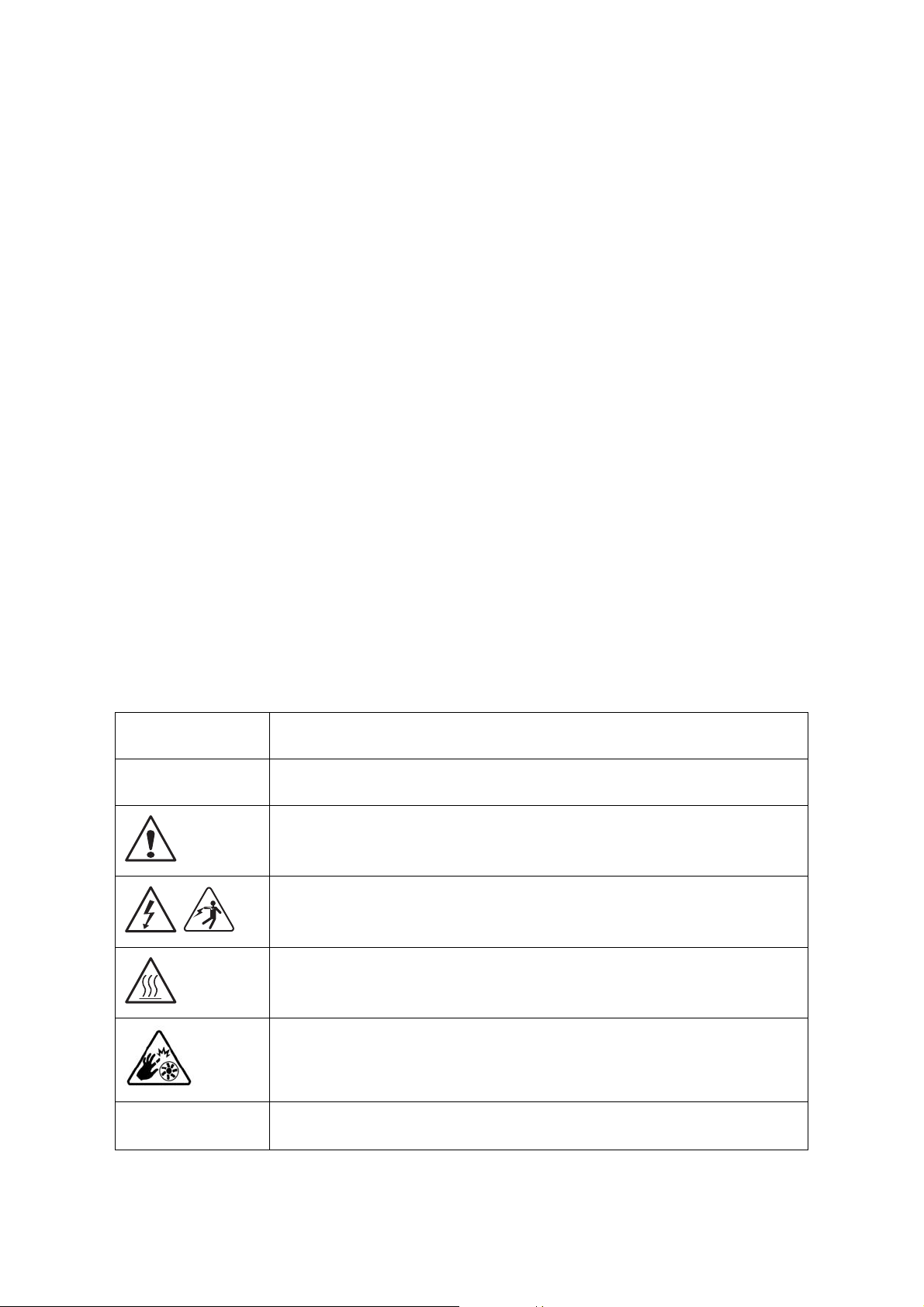
Table 1: Warning and Cautions
CAUTION
WAR NING
Indicates the presence of a hazard that may cause minor personal injury or property damage if the CAUTION is ignored.
Indicates the presence of a hazard that may result in serious personal injury if the
WARNING is ignored.
Indicates potential hazard if indicated information is ignored.
Indicates shock hazards that result in serious injury or death if safety instructions
are not followed.
Indicates hot components or surfaces.
Indicates do not touch fan blades, may result in injury.
Remove the system from the rack to disconnect power system.
VIII
PRECAUTIONARY MEASURES
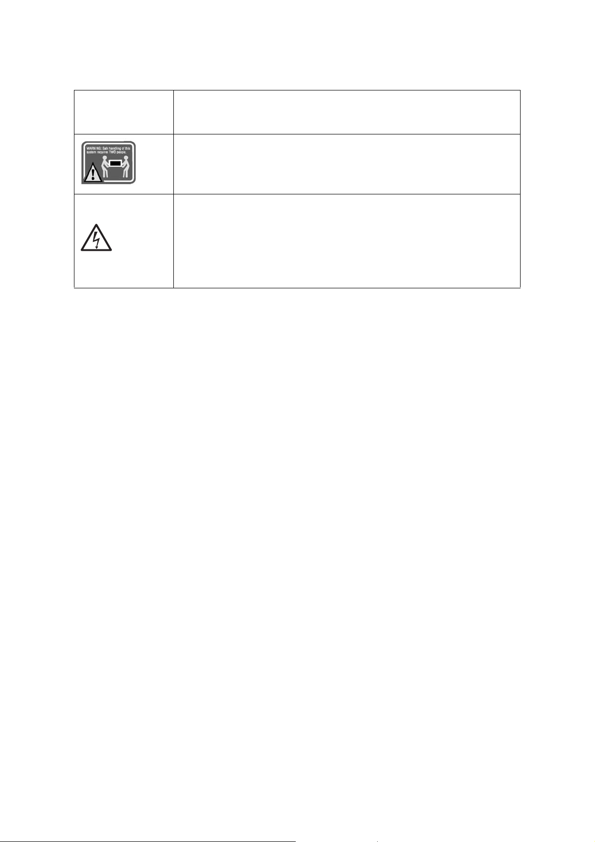
Table 1: Warning and Cautions (Continued)
The enclosure is designed to carry only the weight of the system sled. Do not use
this equipment as a workspace. Do not place additional load onto any equipment
in this system.
Indicates two people are required to safely handle the system.
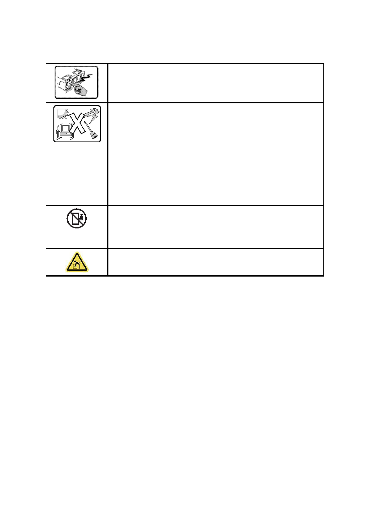
Restricted Access Location: The system is intended for installation only in a
Server Room or Computer Room where both these conditions apply:
access can only be gained by SERVICE PERSONS or by USERS who have been
instructed about the reasons for the restrictions applied to the location and
about any precautions that shall be taken; and
access is through the use of a TOOL or lock and key, or other means of security,
and is controlled by the authority responsible for the location.
Intended Application Uses
This product was evaluated as Information Technology Equipment (ITE), which may be
installed in offices, schools, computer rooms, and similar commercial type locations. The
suitability of this product for other product categories and environments (such as medical,
industrial, residential, alarm systems, and test equipment), other than an ITE application,
may require further evaluation.
Site Selection
The system is designed to operate in a typical office environment. Choose a site that is:
Clean, dry, and free of airborne particles (other than normal room dust).
Well-ventilated and away from sources of heat including direct sunlight and radia-
tors.
Away from sources of vibration or physical shock.
Isolated from strong electromagnetic fields produced by electrical devices.
In regions that are susceptible to electrical storms, we recommend you plug your
system into a surge suppressor and disconnect telecommunication lines to your
modem during an electrical storm.
Provided with a properly grounded wall outlet.
Provided with sufficient space to access the power system, because they serve as the
product's main power disconnect.
Provided with either two independent DC power system or two independent phases
from a single power system.
IX

PRECAUTIONARY MEASURES
CAUTION!
CAUTION!
CAUTION!
CAUTION!
CAUTION!
CAUTION!
!
!
!
!
!
!
Equipment Handling Practices
Reduce the risk of personal injury or equipment damage:
Conform to local occupational health and safety requirements when moving and
lifting equipment.
Use mechanical assistance or other suitable assistance when moving and lifting
equipment.
To reduce the weight for easier handling, remove any easily detachable compo-
nents.
Never lift or move your system soley by the handle on the component.
Power and Electrical Warnings
MAKE SURE THE SYSTEM IS REMOVED FROM THE RACK BEFORE SERVICING ANY NON-HOT PLUG COMPONENTS.
HE BUS BAR CLIPS MUST BE DISCONNECTED FROM THE POWER SYSTEM INORDER TO FULLY SEPARATE THE SYS-
T
TEM FROM THE POWER SOURCE.
TO AVOID RISK OF ELECTRIC SHOCK, DISCONNECT ALL CABLING FROM THE SYSTEM AND REMOVE THE SYSTEM
FROM THE RACK.
System Access Warnings
TO AVOID PERSONAL INJURY OR PROPERTY DAMAGE, THE FOLLOWING SAFETY INSTRUCTIONS APPLY WHENEVER
ACCESSING THE INSIDE OF THE PRODUCT:
Disconnect from the power source by removing the system from the rack.
Disconnect all cabling running into the system.
Retain all screws or other fasteners when servicing. Upon completion servicing, sercure
with original screws or fasteners.
IF THE SERVER HAS BEEN RUNNING, ANY INSTALLED HDD MODULES MAY BE HOT.
UNLESS YOU ARE ADDING OR REMOVING A HOT-PLUG COMPONENT, ALLOW THE SYSTEM TO COOL BEFORE SER-
VICING.
TO AVOID INJURY DO NOT CONTACT MOVING FAN BLADES. IF YOUR SYSTEM IS SUPPLIED WITH A GUARD OVER THE
FAN, DO NOT OPERATE THE SYSTEM WITHOUT THE FAN GUARD IN PLACE.
X

PRECAUTIONARY MEASURES
Rack Mount Warnings
The following installation guidelines are required by UL for maintaining safety compliance
when installing your system into a rack.
The equipment rack must be anchored to an unmovable support to prevent it from tipping when your system or piece of equipment is extended from it. The equipment rack
must be installed according to the rack manufacturer's instructions.
Install equipment in the rack from the bottom up, with the heaviest equipment at the bottom of the rack.
Extend only one piece of equipment from the rack at a time.
You are responsible for installing a main power disconnect for the entire rack unit. This
main disconnect must be readily accessible, and it must be labeled as controlling power to
the entire unit, not just to the system(s).
To avoid risk of potential electric shock, a proper safety ground must be implemented for
the rack and each piece of equipment installed in it.
Elevated Operating Ambient - If installed in a closed or multi-unit rack assembly, the operating ambient temperature of the rack environment may be greater than room ambient.
Therefore, consideration should be given to installing the equipment in an environment
compatible with the maximum ambient temperature (Tma) specified by the manufacturer.
Reduced Air Flow - Installation of the equipment in a rack should be such that the amount
of air flow required for safe operation of the equipment is not compromised.
Mechanical Loading - Mounting of the equipment in the rack should be such that a hazardous condition is not achieved due to uneven mechanical loading.
Circuit Overloading - Consideration should be given to the connection of the equipment
to the supply circuit and the effect that overloading of the circuits might have on over-current protection and supply wiring. Appropriate consideration of equipment nameplate
ratings should be used when addressing this concern.
Reliable Earthing - Reliable earthing of rack-mounted equipment should be maintained.
Particular attention should be given to supply connections other than direct connections
to the branch circuit (e.g. use of power strips).
XI

PRECAUTIONARY MEASURES
CAUTION!
CAUTION!
CAUTION!
!
!
!
Electrostatic Discharge (ESD)
ESD CAN DAMAGE DRIVES, BOARDS, AND OTHER PARTS. WE RECOMMEND THAT YOU PERFORM ALL PROCEDURES
AT AN ESD WORKSTATION. IF ONE IS NOT AVAILABLE, PROVIDE SOME ESD PROTECTION BY WEARING AN ANTI-
STATIC WRIST STRAP ATTACHED TO CHASSIS GROUND -- ANY UNPAINTED METAL SURFACE -- ON YOUR SERVER
WHEN HANDLING PARTS.
Always handle boards carefully. They can be extremely sensitive to ESD. Hold boards only
by their edges without any component and pin touching. After removing a board from its
protective wrapper or from the system, place the board component side up on a
grounded, static free surface. Use a conductive foam pad if available but not the board
wrapper. Do not slide board over any surface.
Cooling and Airflow
CAREFULLY ROUTE CABLES AS DIRECTED TO MINIMIZE AIRFLOW BLOCKAGE AND COOLING PROBLEMS. FOR
PROPER COOLING AND AIRFLOW, OPERATE THE SYSTEM ONLY WITH THE CHASSIS COVERS* / AIR DUCT INSTALLED.
PERATING THE SYSTEM WITHOUT THE COVERS / AIR DUCT IN PLACE CAN DAMAGE SYSTEM PARTS . TO INSTALL
O
THE COVERS* / AIR DUCT:
Check first to make sure you have not left loose tools or parts inside the system.
Check that cables, add-in cards, and other components are properly installed.
Attach the covers* / air duct to the chassis according to the product instructions.
* May not apply to all systems.
Please be aware that slots and openings on the front and rear side of the chassis are
designed for ventilation; to make sure reliable operation of your system and to protect it
from overheating, these openings must not be covered or blocked. The openings should
never be covered or blocked by placing the product on a bed, sofa, rug, or other similar
surface. This product should never be placed near or over a radiator or heat register, or in a
built-in installation unless proper ventilation is provided.
Laser Peripherals or Devices
TO AVOID RISK OF RADIATION EXPOSURE AND / OR PERSONAL INJURY:
Do not open the enclosure of any laser peripheral or device.
Laser peripherals or devices are not serviceable.
Return to manufacturer for servicing.
Use certified and rated Laser Class I for Optical Transceiver product.
Heed safety instructions: Before working with the system, whether using this manual or
any other resource as a reference, pay close attention to the safety instructions. Adhere to
the assembly instructions in this manual to ensure and maintain compliance with existing
product certifications and approvals. Use only the described, regulated components spec-
XII

PRECAUTIONARY MEASURES
ified in this manual. Use of other products / components will void the UL listing and other
regulatory approvals of the product and will most likely result in non-compliance with
product regulations in the region(s) in which the product is sold.
System power on/off: To remove power from system, you must remove the system from
rack. Make sure the system is removed from the rack before opening the chassis, adding,
or removing any non hot-plug components.
Hazardous conditions, devices and cables: Hazardous electrical conditions may be
present on power, telephone, and communication cables. Turn off the system and disconnect the cables attached to the system before opening it. Otherwise, personal injury or
equipment damage can result.
Electrostatic discharge (ESD) and ESD protection: ESD can damage drives, boards, and
other parts. We recommend that you perform all procedures in this chapter only at an ESD
workstation. If one is not available, provide some ESD protection by wearing an antistatic
wrist strap attached to chassis ground any unpainted metal surface on the server when
handling parts.
ESD and handling boards: Always handle boards carefully. They can be extremely sensitive to electrostatic discharge (ESD). Hold boards only by their edges. After removing a
board from its protective wrapper or from the server, place the board component side up
on a grounded, static free surface. Use a conductive foam pad if available but not the
board wrapper. Do not slide board over any surface.
Installing or removing jumpers: A jumper is a small plastic encased conductor that slips
over two jumper pins. Some jumpers have a small tab on top that can be gripped with fingertips or with a pair of fine needle nosed pliers. If the jumpers do not have such a tab,
take care when using needle nosed pliers to remove or install a jumper; grip the narrow
sides of the jumper with the pliers, never the wide sides. Gripping the wide sides can damage the contacts inside the jumper, causing intermittent problems with the function controlled by that jumper. Take care to grip with, but not squeeze, the pliers or other tool used
to remove a jumper, or the pins on the board may bend or break.
General Information
The information about rack and the wording “rack” in this guide supports the organization
of Open Compute definition.
The term Rack as found in this guide referes to the term Rack or Open Rack as described
and used in the Open Compute Project definition.
Before servicing this system, it is recommened to read this technical guide completely to
be aware of any safety issues or requirements involved in the servicing of this system.
XIII
PRECAUTIONARY MEASURES
WARNING!
Assembly Safety Guidelines
The power system in this product contains no user-serviceable parts.
Refer servicing only to qualified personnel.
The system is designed to operate in a typical office environment.
Choose a site that is:
Clean and free of airborne particles (other than normal room dust).
Well ventilated and away from sources of heat including direct sunlight.
Away from sources of vibration or physical shock.
Isolated from strong electromagnetic fields produced by electrical devices.
In regions that are susceptible to electrical storms, we recommend you plug
your system into a surge suppressor and disconnect telecommunication lines
to your modem during an electrical storm.
Provided with a properly grounded wall outlet.
Provided with sufficient space to access the power system, because they serve
as the product's main power disconnect.
The system is safety certified as rack-mounted equipment for use in a server room
or computer room, using an approved customer rack.
The enclosure is designed to carry only the weight of the system sled. Do not place
additional load onto any equipment.
Heavy object. Indicates two people are required to safely handle the system.
XIV

PRECAUTIONARY MEASURES
Structure of this guide
Chapter 1: About the System
“This section introduces the system, its different configuration(s) and the main
features.”
Chapter 2: BIOS
“This section provides information regarding the BIOS architecture, BIOS update
utility, server management, checkpoints, and error handling found in the system.”
Chapter 3: BMC
“This section provides information and key features of BMC (Baseboard Management Controller).”
Chapter 4: Regulatory and Compliance Information
“This section provides regulatory and compliance information applicable to this
system.”
XV

About the System
Chapter 1
This section introduces the system, its different configuration(s) and the main features.

ABOUT THE SYSTEM INTRODUCTION
1.1 Introduction
System Features
The QuantaGrid S31A-1U with four 3.5” HDD is available in two models, a fixed PSU model
and a redundant PSU model. The compact 1U server is built on the Intel® C236 chipset,
featuring the Intel® Xeon® processor E3-1200 v5.
The system is optimized for the dedicated hosting, front-end web, content delivery networks (CDN), and cloud computing applications..
Greener and More Powerful
Powered by the Intel® Xeon® processor E3-1200 v5 product family and DDR4 memory technology, the QuantaGrid S31A-1U allows owners to upgrade computing performance without overextending power consumption. With Quanta’s enhanced
thermal design, the server can operate under ambient temperatures as high as
40°C. This allows owners to save unnecessary costs associated with datacenter cooling needs and achieve higher data center infrastructure efficiency (DCIE) value.
Flexible and Scalable I/O options
QuantaGrid S31A-1U provides flexible I/O scalability for today’s diverse data center
application requirements. It features OCP LAN mezzanine card solutions in addition
to dual GbE or 10GbE LAN on motherboards (LoM). The onboard SAS controller
offers multiple QCT SAS mezzanine card options with different RAID levels and data
transfer bandwidth so customers can tailor the SAS controller for specific application needs.
Specifications
Table 1.1: System Specifications
SPECIFICATIONS DESCRIPTION
Form factor 1U rack mount
Chassis dimensions
(W x H x D)
Processor
17.24 x 1.7 x 24 inches
438 x 43.2 x 609.6 mm
Processor type:
® Xeon® processor E3-1200 v5 product family
Intel
Max. TDP support: 80W
Number of processor: 1
Last Level Cache (LLC): Up to 8 MB
Chipset
Memory
® C236
Intel
Total slots: 4
Capacity: Up to 64GB ECC UDIMM
Memory type: 2133 MHz DDR4 ECC UDIMM
Memory size: 16 GB, 8 GB, 4GB ECC UDIMM
1-1

ABOUT THE SYSTEM INTRODUCTION
Table 1.1: System Specifications (Continued)
SPECIFICATIONS DESCRIPTION
Onboard (Intel® C236):
2 mini-SAS HD connectors suppoting 8x SATA 6Gb/s ports
Storage controller
Networking
Expansion slot
2x M.2 connector supporting SATA or PCIe SSD
Optional controller:
Please refer to our Compatible Component List for more information
LOM:
2x Intel® I210 GbE port
Dedicated GbE management port
Optional NIC:
Please refer to our Compatible Component List for more information
Riser
PCIe Expansion Card Riser: One x 8 PCIe 3.0, Low profile MD-2
QCT mezzanine Riser: One x8 PCIe 3.0, SAS mezzanine slot
OCP mezzanine slot
One x8 PCIe 3.0 slot
Storage
4x 3.5" hot-plug SAS/SATA HDD/SSD
2x 2.5” internal SATA SSD
Onboard storage 2x M.2 SSD (SATA or PCIe)
Video Integrated Aspeed AST2400 with 8MB DDR3 video memory
Power/ID/Reset Buttons
Front I/O
Rear I/O
LAN/HDD/Status/ID LEDs
2x USB 2.0 ports
2x USB 3.0 ports
1x VGA port
1x RS232 serial port
2x GbE RJ45 port
1x GbE RJ45 management port
1x ID button with LED
TPM Yes (optional)
SKU1: 1+1 redundant hot-plug PSU, 80 Plus Platinum
3Y 700W 100-240Vac, 50-60Hz, 10-5A
Power supply
3Y 400W 100-240Vac, 50-60Hz, 6-3A
Acbel 700W 100-127/200-240Vac, 50/60Hz, 9.5/5A
Acbel 400W 100-127/200-240Vac, 50/60Hz, 6/3A
SKU2: 1x fixed PSU, 80 Plus Platinum
Rating (per PSU inlet) 100-127/200-240Vac, 50/60Hz, 4/2A
Fan 3x dual rotor fans (5+1 redundant)
System management IPMI v2.0 Compliant, on board "KVM over IP" support
Operating temperature: 5°C to 40°C (41°F to 104°F)
Operating environment
Non-operating temperature: -40°C to 70°C (-40°F to 158°F)
Operating relative humidity: 50% to 85%RH.
Non-operating relative humidity: 20% to 90%RH
1-2

ABOUT YOUR SYSTEM PACKAGE CONTENTS
Note:
1.2 Package Contents
(1) S31A-1U system
(1) processor heat sink
(1) power supply unit
(1) power cord (optional)
(1) utility CD (This Guide included)
(1) rail kit
Note: For exact shipping contents, contact your sales representative.
1-3
ABOUT THE SYSTEM A TOUR OF THE SYSTEM
2
5
7
10
1
6
4
3
9
8
11
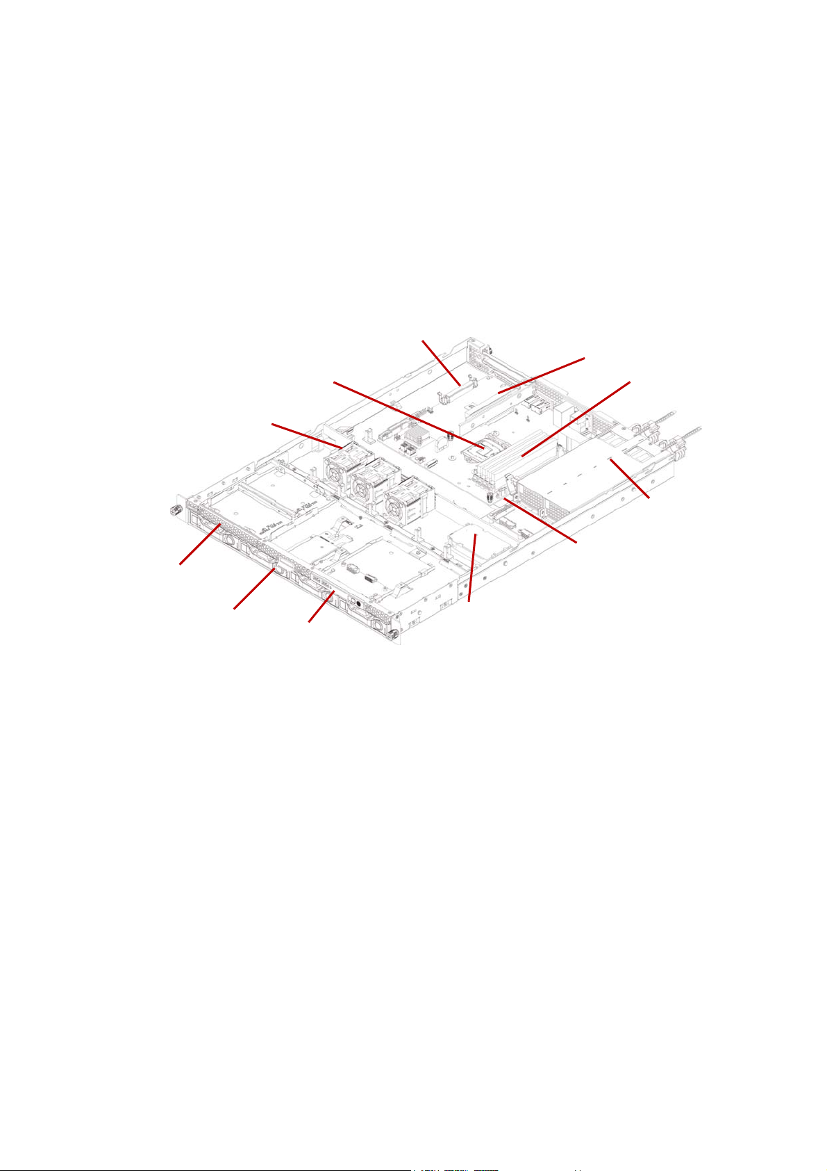
1.3 A Tour of the System
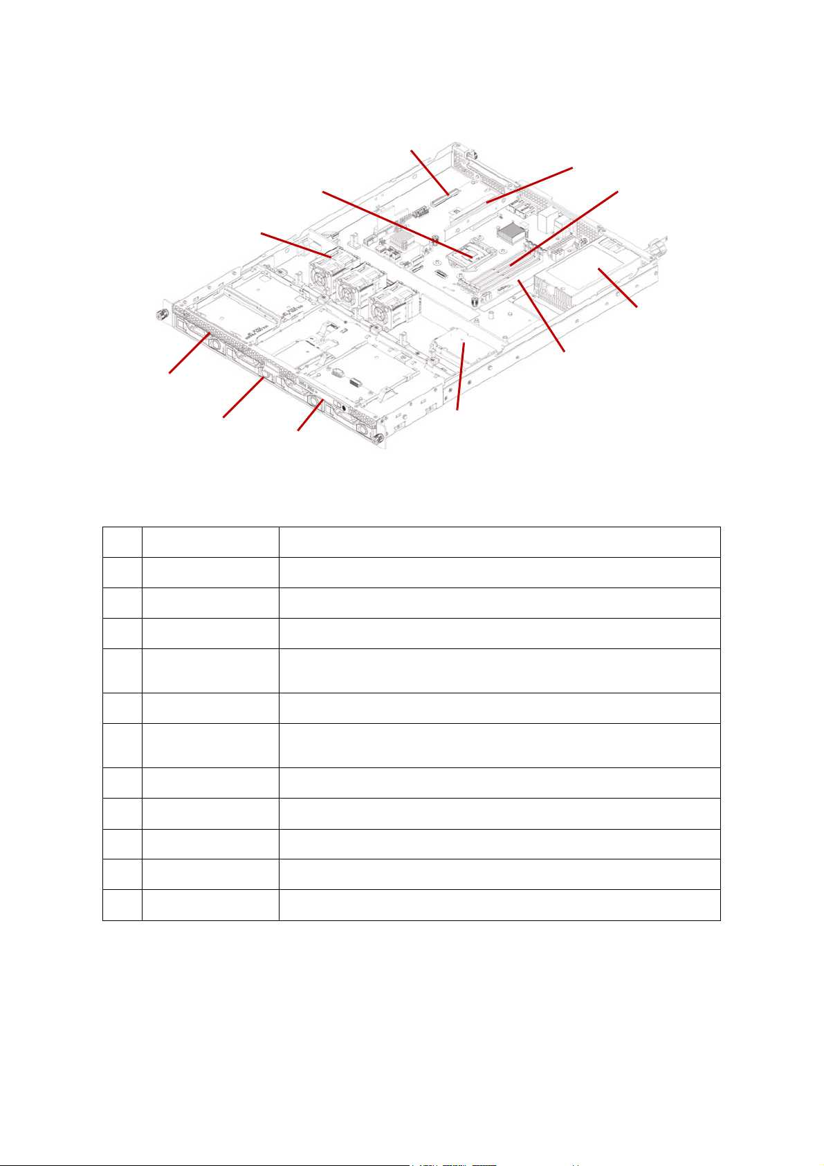
System Overview
The server is available as a redundant PSU (SKU1) and fixed PSU (SKU2) configuration.
The redundant PSU SKU configuration system overview is displayed in the following
image:
Figure 1-1. Redundant PSU System (SKU1) Component Overview
1-4
ABOUT THE SYSTEM SYSTEM OVERVIEW
2
5
7
10
1
6
4
3
9
8
11
The fixed PSU configuration system overview is displayed in the following image:
Figure 1-2. Fixed PSU System (SKU2) Component Overview
Table 2: Component Overview
NO.ITEM DESCRIPTION
1 Fan module (3) System fan modules
2 CPU socket LGA 1151 socket
3 OCP mezz slot Support OCP mezzanine card, PCIe x8, Gen 3.0
4 Riser assembly
5 DIMM slots (4) DDR4 DIMM slots
6 PSU assembly
7 Mainboard System mainboard
8 Backup battery Backup battery for SAS mezzanine card
9 Front control panel See Front Control Panel (FCP) on page 1-6
10 HDD assembly 4 x 3.5” SAS/SATA hard disk drive assemblies
11 SSD assembly 2 x solid state disk drive assemblies.
Support PCIe expansion card, PCIe x 8, Gen 3.0
Support QCT SAS mezzanine card, PCIe x 8, Gen 3.0
SKU1: Redundant power supply unit assembly
SKU2: Fixed power supply unit assembly
1-5
ABOUT THE SYSTEM SYSTEM FRONT VIEW
2
13
9
1 65432
7 8
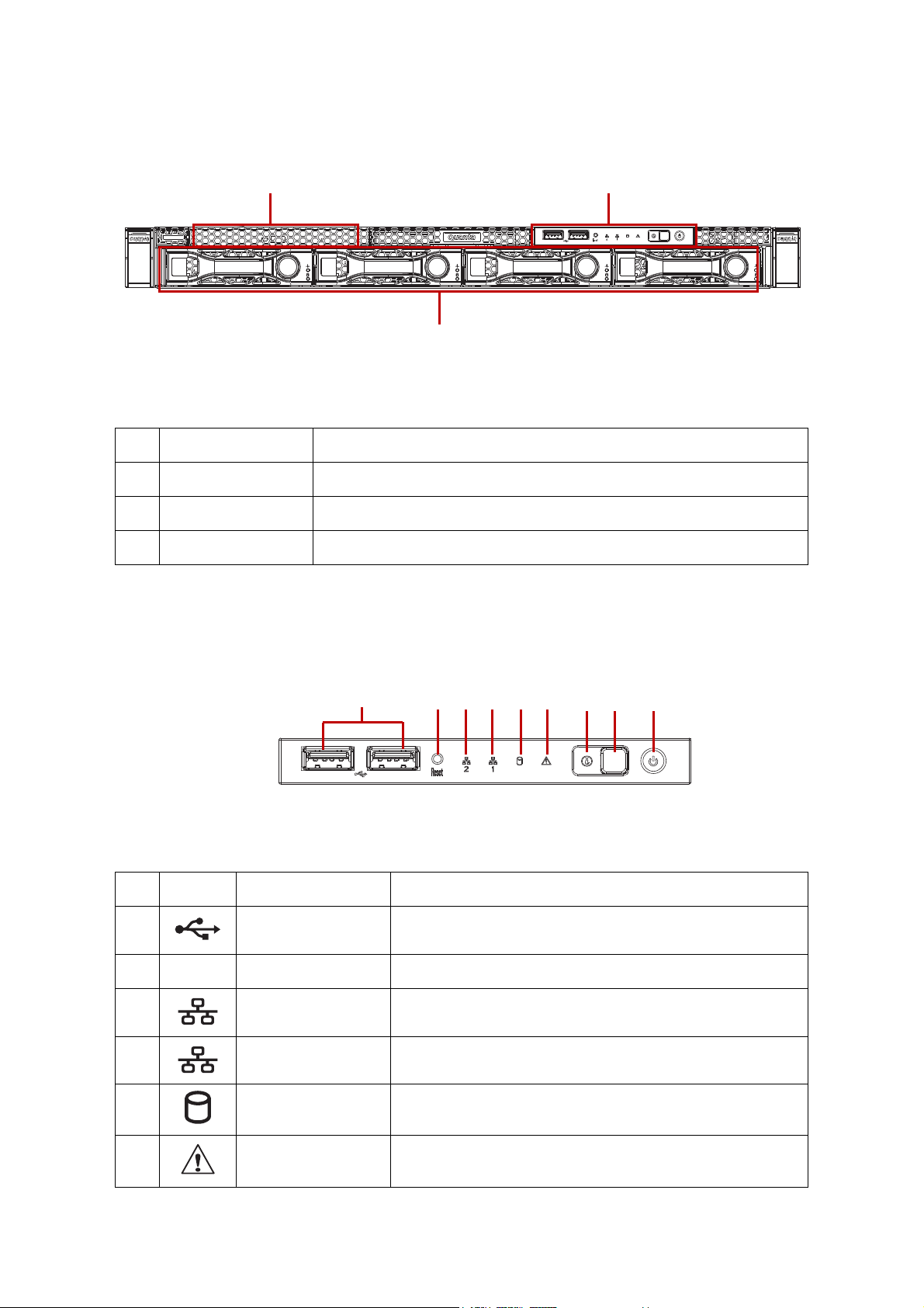
System Front View
Figure 1-3. System Front View
Table 3: Front Panel View
NO.NAME DESCRIPTION
1 Front control panel See Front Control Panel LED on page 1-9 for further information.
2 HDD bays 4 x 3.5” SAS/SATA HDD
3 SSD tray 2 x SSD
Front Control Panel (FCP)
For purposes of this procedure, the FCP is used for the numbering indicators.
Figure 1-4. Front Control Panel
Table 4: Front Control Panel Definition
NO.ICON NAME DESCRIPTION
1 USB ports USB ports 1 & 2
2 Reset button Soft reset system function
3 LAN2 LED LAN access
4 LAN1 LED LAN access
5 HDD activity LED Hard disk drive access
6 Fault LED Provides critical and non-critical failure notification
1-6
ABOUT THE SYSTEM SYSTEM REAR VIEW
1
2
23 4
Table 4: Front Control Panel Definition (Continued)
NO.ICON NAME DESCRIPTION
7 Identification LED Activate ID LED to identify system
8 ID button Toggles ID LED
9 Power button Power on / off
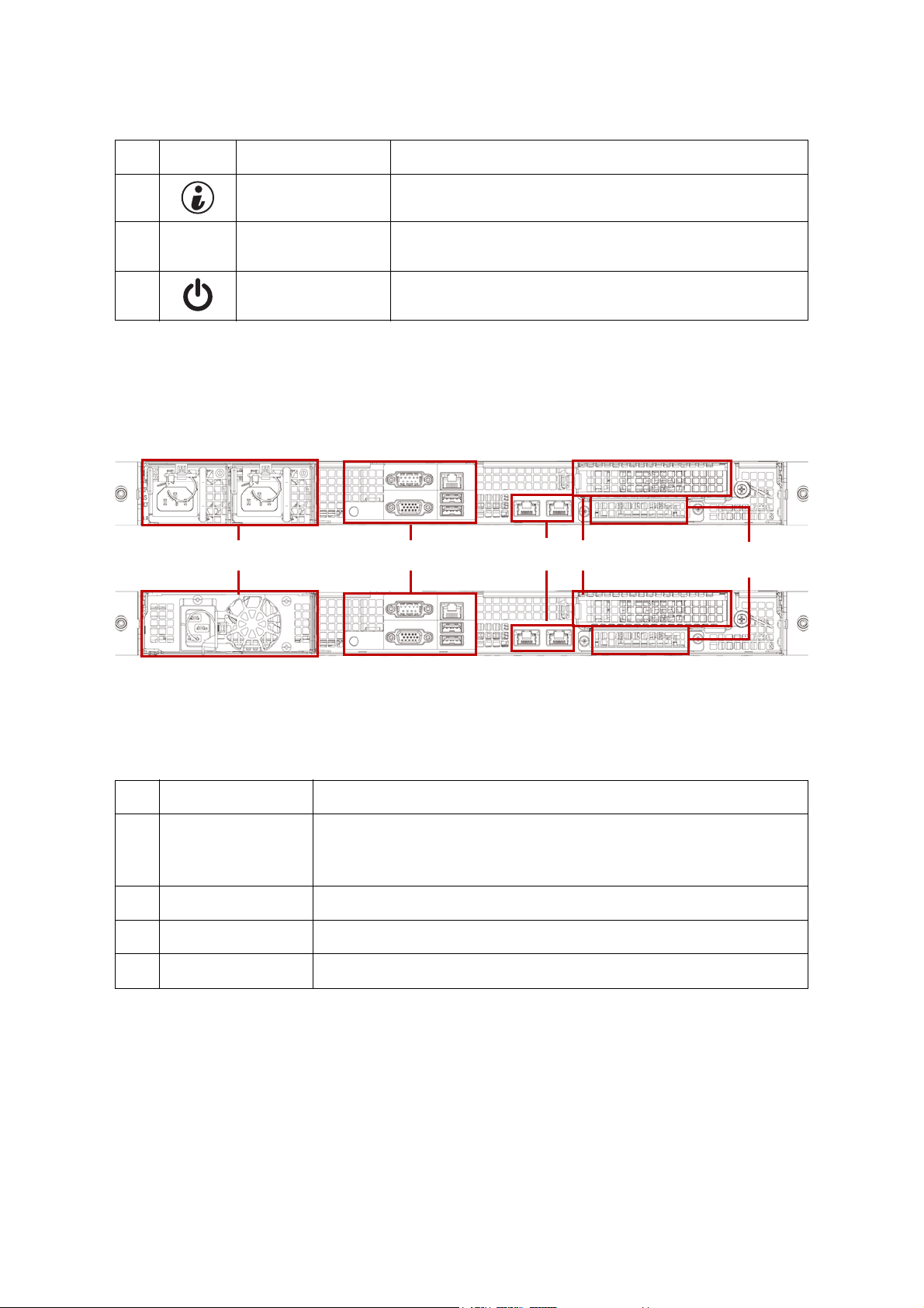
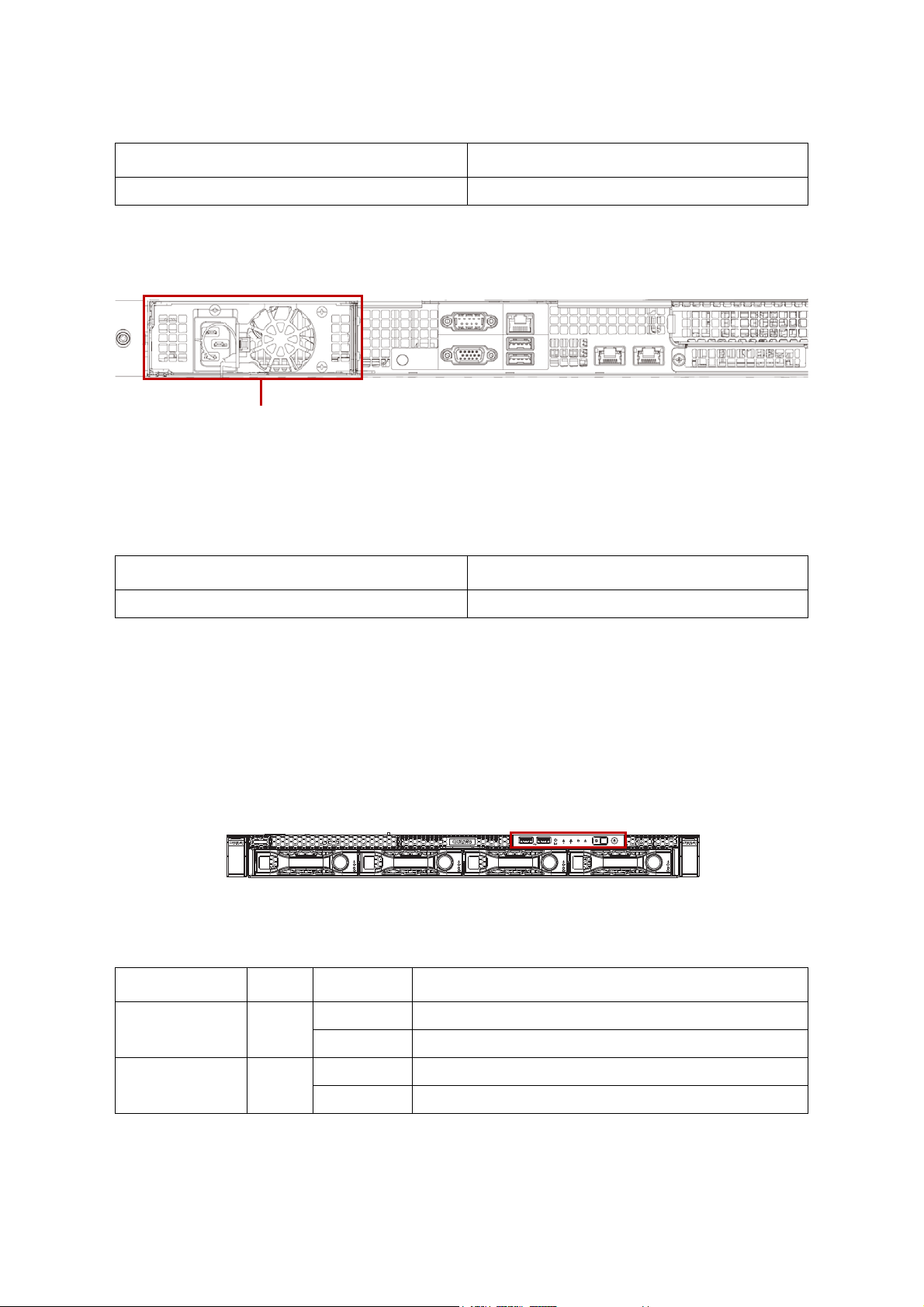
System Rear View
Figure 1-5. System Rear View
Table 5: System Rear View
NO.FEATURE DESCRIPTION
Upper: Redundant power supply unit.
1 Power sub-system
2 System I/O ports See System Rear I/O on page 1-8
3 Expansion slot PCIe expansion slot with PCIe x8 signal
4 OCP mezzanine slot Support OCP mezzanine card with PCIe x 8 signal
Bottom: Fixed power supply unit.
See Power Sub-System (Redundant PSU SKU) on page 1-8.
1-7
ABOUT THE SYSTEM SYSTEM REAR VIEW
23 45 617
PSU
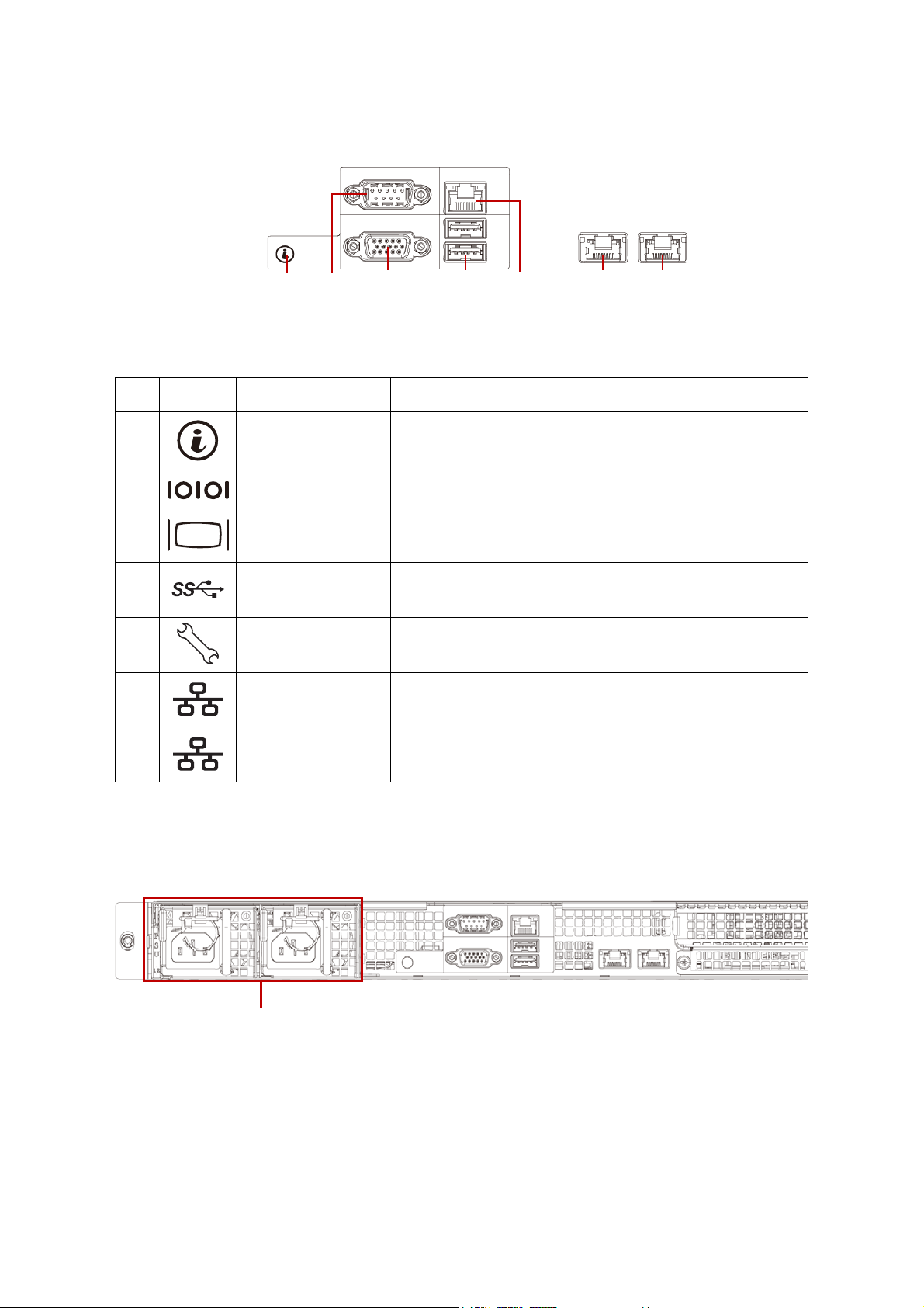
System Rear I/O
Figure 1-6. System Rear I/O
Table 6: System Rear I/O Defintition
NO.ICON NAME DESCRIPTION
1 ID button with LED Toggle the identification when pressing
2 COM port DB9 port for debug or terminal concentrator
3VGA connector
4 USB ports USB 3.0 ports
5 Dedicated NIC Dedicated RJ45 connector
6 LAN2 RJ45 connector featuring share NIC
7LAN1 RJ45 connector
Maximum display resolution: 1920x1200 32bpp@60Hz
(reduced blanking)
Power Sub-System (Redundant PSU SKU)
Figure 1-7. Redundant PSU to Mainboard Module Description
A single power supply unit (default) and power distribution board (PDB) are supplied in
the system. A secondary PSU is available for redundacy functionality.
1-8
ABOUT THE SYSTEM LED STATUS DEFINITIONS
PSU
Table 7: Power Supply Units by Model
PSU AC INPUT
2 x 400W high efficiency redundant PSU 100-240V AC 50/60Hz
Power Sub-System (Fixed PSU SKU)
Figure 1-8. Fixed PSU to Mainboard Module Description
A fixed power supply unit is supplied in the system.
Table 8: Power Supply Units by Model
PSU AC INPUT
1 x 400W high efficiency PSU 100-240V AC 50/60Hz
LED Status Definitions
Front Control Panel LED
For further information and location of the FCP LEDs, see Front Control Panel LED on
page 1-9.
Figure 1-9. System Front Control Panel LEDs
Table 9: Front Control Panel LED Behavior
NAME COLOR CONDITION DESCRIPTION
Power LED Blue
Identification Blue
On System power on
Off System power off
Blinking Unit selected for identification
Off No identification request
1-9
ABOUT THE SYSTEM LED STATUS DEFINITIONS
Link
Activity
PIN 1
Location
Table 9: Front Control Panel LED Behavior (Continued)
NAME COLOR CONDITION DESCRIPTION
Critical Failure: critical fan, voltage, temperature state.
Blinking
Fault LED Amber
Off
Non-Critical Failure: non-critical fan, voltage, temperature
state, CPU thermal trip, DC off.
SEL cleared
Last pending warning or error has been de-asserted.
HDD activity Blue
LAN1 LED Blue
LAN2 LED Blue
Blinking Hard disk drive access (only on board SATA port)
Off No access (non-SAS)
On Link
Blinking LAN access (off when there is traffic)
On Link
Blinking LAN access (off when there is traffic)
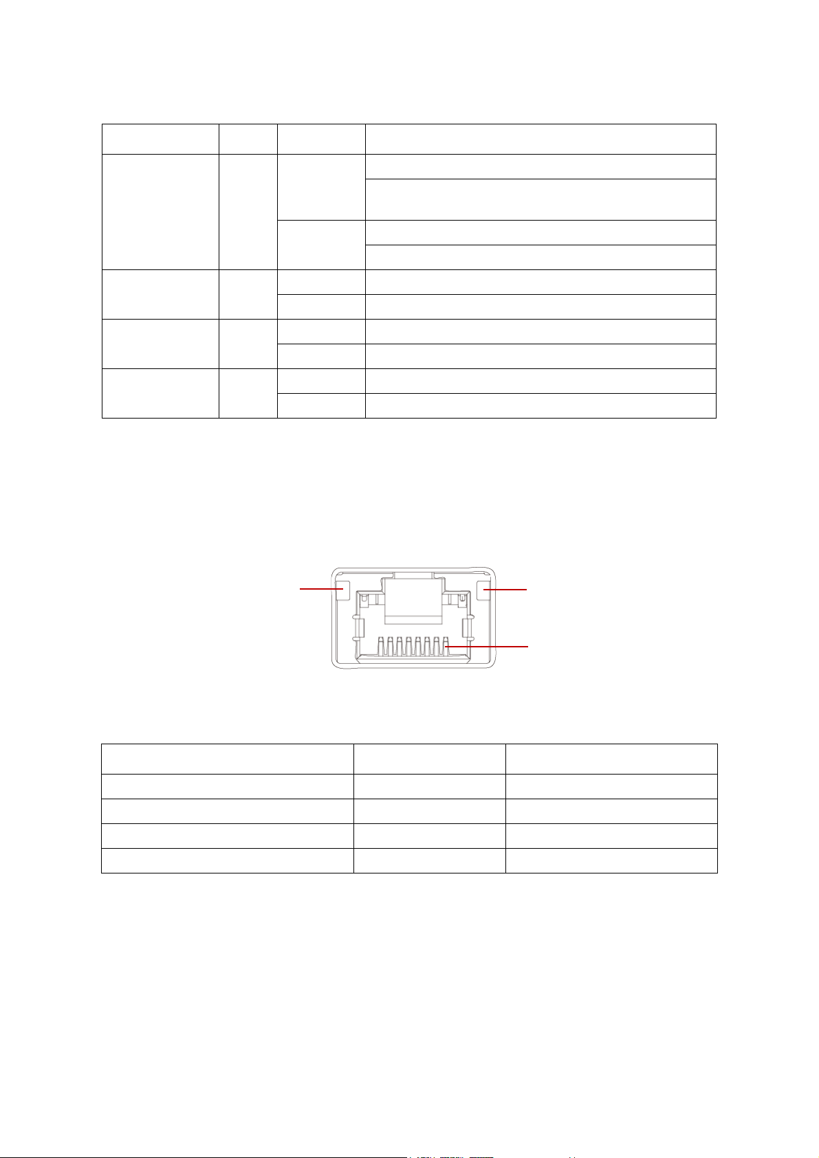
LAN LED
The system mainboard includes dual GbE network with GbE dedicated management port.
Each RJ45 connector has two built-in LEDs. See the following illustration and table for
details.
Figure 1-10. RJ45 LAN Connector
Table 10: RJ45 LED Description
CONDITION LINK ACTIVITY
Unplugged Off Off
1G active link On amber Blinking green
100M active link On green Blinking green
10M active link Off Blinking green
1-10
ABOUT THE SYSTEM LED STATUS DEFINITIONS
Link
Activity
PIN 1
Location
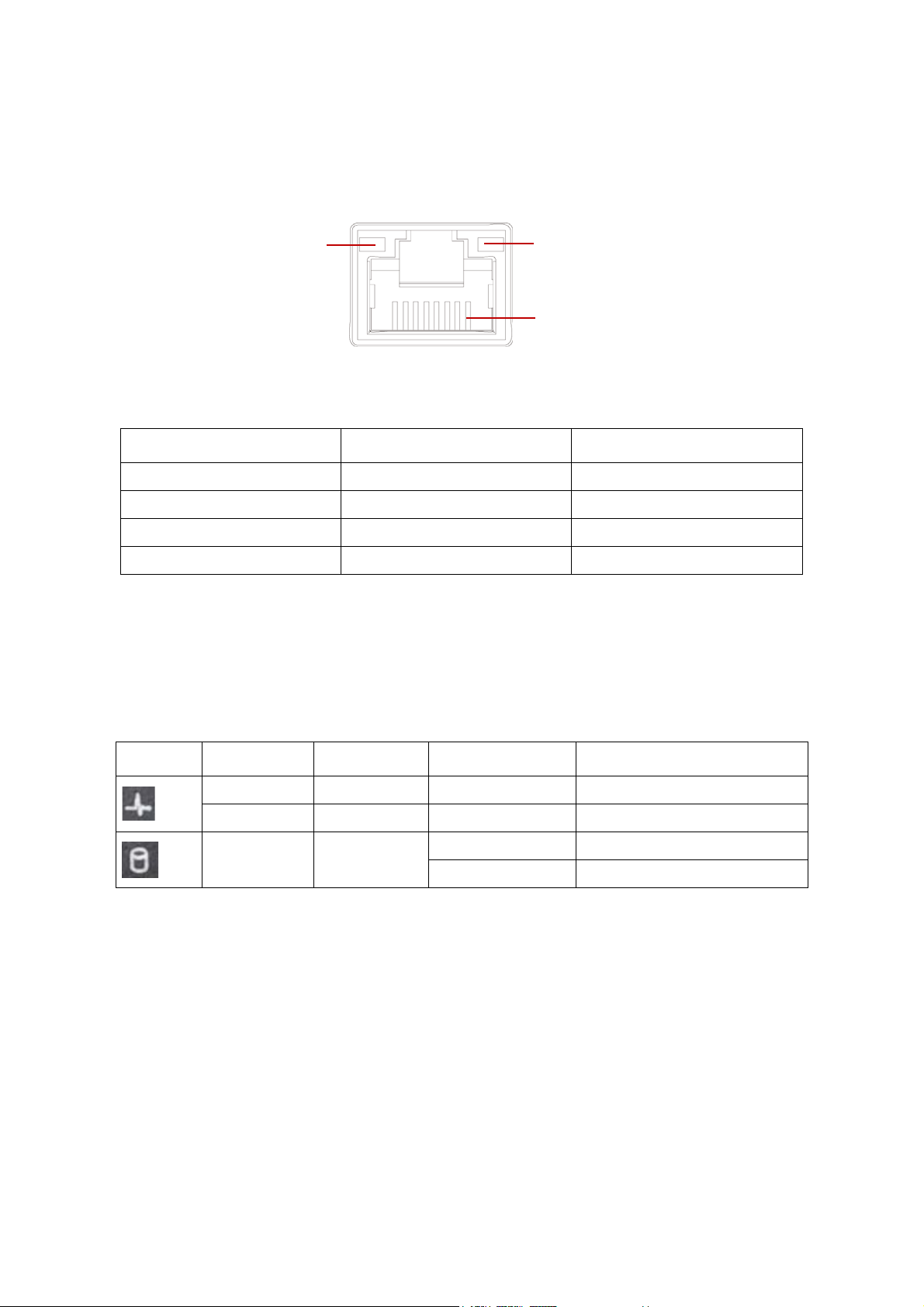
BMC Management Port LED
The system mainboard includes GbE dedicated management port. The RJ45 connector
has two built-in LEDs. See the following illustration and table for details.
Figure 1-11. RJ45 LAN Connector
Table 11: RJ45 LED Description
CONDITION LINK ACTIVITY
Unplugged Off Off
1G active link On amber Blinking green
100M active link On green Blinking green
10M active link Off Blinking green
HDD LED
The following LED behavior table represents LED conditions when a driver is online and
the slot is not empty.
Table 12: HDD LED Status Behavior
ICON NAME COLOR CONDITION DESCRIPTION
HDD Present Blue On Drive is online
HDD Fault Amber On HDD failure
HDD Access Blue
* Only support SATA/SAS HDD/SSD.
Blinking HDD access is active
Off No access
1-11

BIOS
Chapter 2
This section provides information regarding the BIOS architecture, BIOS update utility,
server management, checkpoints, and error handling found in the system.

BIOS BIOS SETUP UTILITY
2.1 BIOS Setup Utility
The BIOS Setup utility is provided to perform system configuration changes and to display
current settings and environment information.
The BIOS Setup utility stores configuration settings in system non-volatile storage.
Changes affected by BIOS Setup will not take effect until the system is rebooted. The BIOS
Setup Utility can be accessed during POST by using the <DEL> or <F2> key.
The following sections describe the look and behavior for platform Setup.
Operation
BIOS Setup has the following features:
The server board BIOS will only be available in English.
BIOS Setup is functional via console redirection over various terminal emulation
standards. This may limit some functionality for compatibility, e.g., usage of colors,
some keys or key sequences, or support of pointing devices.
Setup Page Layout
The setup page layout is sectioned into functional areas. Each occupies a specific area of
the screen and has dedicated functionality. The following table lists and describes each
functional area.
Table 1: BIOS Setup Page Layout
FUNCTIONAL AREA DESCRIPTION
Title Bar
Setup Item List
Item Specific Help
Area
Keyboard Command Bar
The title bar is located at the top of the screen and displays the title of the form
(page) the user is currently viewing. It may also display navigational information.
The Setup Item List is a set of controllable and informational items. Each item in the
list occupies the left column of the screen.
A Setup Item may also open a new window with more options for that functionality on the board.
The Item Specific Help area is located on the right side of the screen and contains
help text for the highlighted Setup Item. Help information may include the meaning and usage of the item, allowable values, effects of the options, etc.
The Keyboard Command Bar is located at the bottom right of the screen and continuously displays help for keyboard special keys and navigation keys.
Entering BIOS Setup
BIOS Setup is started by pressing <DEL> or <F2> during boot time when the OEM
(Quanta) logo is displayed.
2-1

BIOS KEYBOARD COMMANDS
When Quiet Boot is disabled, the message “press <DEL> or <F2> to enter setup” will be
displayed on the diagnostics screen.
Keyboard Commands
The bottom right portion of the Setup screen provides a list of commands that are used to
navigate through the Setup utility. These commands are displayed at all times.
Each Setup menu page contains a number of features. Except those used for informative
purposes, each feature is associated with a value field. This field contains user-selectable
parameters. Depending on the security option chosen and in effect by the password, a
menu feature's value may or may not be changeable. If a value is non-changeable, the feature's value field is inaccessible and displays as "grayed out."
Table 2: Keyboard Commands
KEY OPTION DESCRIPTION
The <Enter> key is used to activate sub-menus when the selected
feature is a sub-menu, or to display a pick list if a selected option has
<Enter>Execute Command
a value field, or to select a sub-field for multi-valued features like time
and date. If a pick list is displayed, the <Enter> key will select the currently highlighted item, undo the pick list, and return the focus to the
parent menu.
<Esc> Exit
↑
↓
←→
<Tab > Select Field
Select Item
Select Item
Select Menu
The <Esc> key provides a mechanism for backing out of any field.
When the <Esc> key is pressed while editing any field or selecting
features of a menu, the parent menu is re-entered.
When the <Esc> key is pressed in any sub-menu, the parent menu is
re-entered. When the <Esc> key is pressed in any major menu, the
exit confirmation window is displayed and the user is asked whether
changes can be discarded. If “No” is selected and the <Enter> key is
pressed, or if the <Esc> key is pressed, the screen is returned to the
one before pressing the <Esc> key, without affecting any existing
any settings. If “Yes” is selected and the <Enter> key is pressed, setup
is exited and the BIOS returns to the main System Options Menu
screen.
The up arrow is used to select the previous value in a pick list, or the
previous option in a menu item's option list. The selected item must
then be activated by pressing the <Enter> key.
The down arrow is used to select the next value in a menu item's
option list, or a value field's pick list. The selected item must then be
activated by pressing the <Enter> key.
The left and right arrow keys are used to move between the major
menu pages. The keys have no affect if a sub-menu or pick list is displayed.
The <Ta b> key is used to move between fields. For example, <Tab >
can be used to move from hours to minutes in the time item in the
main menu.
2-2

BIOS KEYBOARD COMMANDS
Load Optimized Defaults?
Yes N o
Load Optimized Defaults?
Yes N o
Save configuration and exit?
Yes N o
Table 2: Keyboard Commands (Continued)
KEY OPTION DESCRIPTION
The minus key on the keypad is used to change the value of the cur-
- Change Value
+ Change Value
kScroll Bar
mScroll Bar
rent item to the previous value. This key scrolls through the values in
the associated pick list without displaying the full list.
The plus key on the keypad is used to change the value of the current
menu item to the next value. This key scrolls through the values in
the associated pick list without displaying the full list. On 106-key
Japanese keyboards, the plus key has a different scan code than the
plus key on the other keyboard, but will have the same effect.
The k key is used to scroll up in the item specific help area. The scroll
bar keys have no affect if help string was not longer than the maximum allocated space in item specific help area.
The m key is used to scroll down in the item specific help area. The
scroll bar keys have no affect if help string was not longer than the
maximum allocated space in item specific help area.
Pressing <F8> causes the following to appear:
<F8> Previous Values
<F9> Setup Defaults
If Yes is highlighted and <Enter> is pressed, all Setup fields are set to
their previous values. If No is highlighted and <Enter> is pressed, or if
the <Esc> key is pressed, the screen is returned to the one before
<F8> was pressed without affecting any existing field values
Pressing <F9> causes the following to appear:
If Yes is highlighted and <Enter> is pressed, all Setup fields are set to
their default values. If No is highlighted and <Enter> is pressed, or if
the <Esc> key is pressed, the screen is returned to the one before
<F9> was pressed without affecting any existing field values
Pressing <F10> causes the following message to appear:
<F10> Save and Exit
If Yes is highlighted and <Enter> is pressed, all changes are saved
and Setup is exited. If No is highlighted and <Enter> is pressed, or
the <Esc> key is pressed, the screen is returned to the one before
<F10> was pressed without affecting any existing values.
2-3

BIOS MENU SELECTION BAR
Menu Selection Bar
The Menu Selection Bar is located at the top of the BIOS Setup Utility screen. It displays the
major menu selections available to the user. By using the left and right arrow keys, the
user can select the menus listed here.
Server Platform Setup Utility Screens
The sections below describe the screens available for the configuration of a server platform. In these sections, tables are used to describe the contents of each screen. These
tables follow the following guidelines:
The text and values in the Setup Item, Options, and Help columns in the tables are
displayed on the BIOS Setup screens.
Bold text in the Options column of the tables indicates default values. These values
are not displayed in bold on the setup screen. The bold text in this document is to
serve as a reference point.
The Comments column provides additional information where it may be helpful.
This information does not appear in the BIOS Setup screens.
Information in the screen shots that is enclosed in brackets (< >) indicates text that
varies, depending on the option(s) installed. For example <Current Date> is replaced
by the actual current date.
Information that is enclosed in square brackets ([ ]) in the tables indicates areas
where the user needs to type in text instead of selecting from a provided option.
Whenever information is changed (except Date and Time) the systems requires a
save and reboot to take place. Pressing <ESC> will discard the changes and boot the
system according to the boot order set from the last boot.
2-4

BIOS MAIN SCREEN
Main Screen
Figure 2-1. Main Screen
Table 3: Main Screen Description
SETUP ITEM OPTIONS HELP TEXT COMMENTS
BIOS Vendor
Core Version
Compliancy
Project Version
Build Date and
Time
Tota l Memor y
Access Level
System Date
[Day of week
MM/DD/YYYY]
Set the Date. Use Tab to switch
between Date elements.
Information only. Displays the
BIOS Vendor.
Information only. Displays the
AMI BIOS Core version.
Information only. Displays the
BIOS compliancy.
Information only. Displays the
Project version.
Information only. Displays the
BIOS build date.
Information only. Displays the
Total System Memory Size.
Information only. Displays the
Total System Memory Size.
Valid range of year : 1998~2099.
System Time [HH:MM:SS]
Set the Time. Use Tab to switch
between Time elements.
2-5

BIOS ADVANCED SCREEN
Advanced Screen
The Advanced screen provides an access point to configure several options. On this
screen, the user selects the option that is to be configured. Configurations are performed
on the selected screen, not directly on the Advanced screen.
To access this screen from the Main screen, press the right arrow until the Advanced
screen is chosen.
Figure 2-2. Advanced Screen
Table 4: Advanced Screen Description
SETUP ITEM OPTIONS HELP TEXT COMMENTS
Trusted Computing Trusted Computing Settings
Runtime Error Logging
Super IO Configuration System Super IO Chip Parameters.
Serial Port Console Redirection Serial Port Console Redirection
CPU Configuration CPU Configuration Parameters
SATA Configuration SATA Device Opton Settings
CSM Configuration
USB Configuration USB Configuration Parameters
WHEA Configuration General WHEA Configuration Settings
Runtime Erro Logging Support Setup
Options
CSM configuration: Enable/Disable, Option
ROM execution settings, etc.
2-6

BIOS CHIPSET SCREEN
Table 4: Advanced Screen Description (Continued)
SETUP ITEM OPTIONS HELP TEXT COMMENTS
Onboard Device Configuration Onboard Device Parameters
iSCSI Configuration Configure the iSCSI Parameters Dynamic
Chipset Screen
The Chiptset screen provides an access point to configure several options. On this screen,
the user selects the option that is to be configured. Configurations are performed on the
selected screen, not directly on the Chipset screen.
To access this screen from the Main screen, press the right arrow until the Chipset screen is
chosen.
Figure 2-3. Chipset Screen
Table 5: Chipset Screen Description
SETUP ITEM OPTIONS HELP TEXT COMMENTS
[Custom]
[Energy-Saving Mode]
Pwr/Perf Profiles
Intel Server Platform Services
[Balanced Mode]
[Virtualization Mode]
[HPC Mode]
Configure your own power
and performance settings
under Custom or adopt quick
setting profiles.
Intel Server Platform Services
Parameters
2-7

BIOS SERVER MANAGEMENT SCREEN
Table 5: Chipset Screen Description (Continued)
SETUP ITEM OPTIONS HELP TEXT COMMENTS
System Agent (SA) Configuration System Agent (SA) Parameters
PCH-IO Configuration PCH Parameters
Server Management Screen
The Server Management screen displays information of the BMC, and allows the user to
configure desired settings.
To access this screen from the Main screen, select Server Mgmt Options.
Figure 2-4. Server Management Screen
Table 6: Server Management Screen Description
SETUP ITEM OPTIONS HELP TEXT COMMENTS
BMC Self Test
Status
BMC firmware
version
IPMI version
FRB-2 Timer
[Enabled]
[Disabled]
Enable or Disable FRB2 timer
(POST timer)
Information only. Displays the
BMC Self Test Status.
Information only. Displays the
BMC firmware version.
Information only. Displays the
IPMI version.
2-8

BIOS BOOT OPTIONS SCREEN
Table 6: Server Management Screen Description (Continued)
SETUP ITEM OPTIONS HELP TEXT COMMENTS
[3 minutes]
FRB-2 Timer
timeout
[4 minutes]
[5 minutes]
[6 minutes]
Enter value Between 3 to 6 min
for FRB-2 Timer Expiration value
Not available if FRB2 Timer is disabled.
FRB-2 Timer Policy
OS Watchdog
Timer
OS Wtd Timer
Timeout
OS Wtd Timer
Policy
System Event
Log
[Do Nothing]
[Reset]
[Power Down]
[Enabled]
[Disabled]
[5 minutes]
[10 minutes]
[15 minutes]
[20 minutes]
[Do Nothing]
[Reset]
[Power Down]
Configure how the system
should respond if the FRB2 Timer
expires. Not available if FRB2
Timer is disabled.
If enabled, starts a BIOS timer
which can only be shut off by
Intel Management Software after
the OS loads. Helps determine
that the OS successfully loaded
or follows the O/S Boot Watchdog Timer policy.
Configure the length of the OS
Boot Watchdog Timer. Not available if OS Boot Watchdog Timer
is disabled.
Configure how the system
should respond if the O/S Boot
Watchdog Timer expires. Not
available if O/S Boot Watchdog
Timer is disabled.
Press <Enter> to change the SEL
event log configuration.
Not available if FRB2 Timer is disabled.
View FRU information
BMC network
configuration
Restore on AC
Power Loss
Current Restore
on AC Power
Loss
[Power Off]
[Power On]
[Last State]
[No Change]
Press <Enter> to view FRU information.
Configure BMC network parameters
System action to take on AC
power loss
Current system action to take on
AC power loss.
Boot Options Screen
The Boot Options screen displays any bootable media encountered during POST, and
allows the user to configure desired boot device.
2-9

BIOS BOOT OPTIONS SCREEN
If no boot devices are available – for example, both onboard LAN are disabled and no
bootable device connected when Boot Mode is set to Legacy – the system will auto boot
into BIOS setup menu.
To access this screen from the Main screen, select Boot Options.
Figure 2-5. Boot Options Screen
Table 7: Boot Options Screen Description
SETUP ITEM OPTIONS HELP TEXT COMMENTS
Number of seconds to wait for
Setup Prompt
Timeout
Bootup NumLock State
POST Error
Pause
Quiet Boot
Boot mode
select
[<number>}
[On]
[Off ]
[Disabled]
[Enabled]
[Disabled]
[Enabled]
[LEGACY]
[UEFI]
setup activation key.
Default is 5 seconds, max is 10
and min is 1.
Select the keyboard NumLock
state
Enables or disables POST
Error Pause
Enables or disables Quiet
Boot option
Select boot mode LEGACY/
UEFI
This item decides what devices
(Legacy or UEFI) BIOS should try
to boot when let the system auto
boot up without manually select
boot device.
2-10

BIOS SECURITY SCREEN
Table 7: Boot Options Screen Description (Continued)
SETUP ITEM OPTIONS HELP TEXT COMMENTS
[<Device String 1>]
Boot Option #1
Boot Option #2
Boot Option #3
Boot Option #4
[<Device String 2>]
…
[Disabled]
[<Device String 1>]
[<Device String 2>]
…
[Disabled]
[<Device String 1>]
[<Device String 2>]
…
[Disabled]
[<Device String 1>]
[<Device String 2>]
…
[Disabled]
Sets the system boot order
Sets the system boot order
Sets the system boot order
Sets the system boot order
Hard Drive BBS
Priorities
Network Device
BBS Priorities
CD/DVD ROM
Drive BBS Priorities
Floppy Drive
BBS Priorities
Set the order of the legacy
devices in this group
Set the order of the legacy
devices in this group
Set the order of the legacy
devices in this group
Set the order of the legacy
devices in this group
Only appears when at least one
Hard Disk is detected.
Only appears when at least one
CD/DVD Drive is detected.
Security Screen
The Security screen provides fields to enable and set the user and administrative password
and to lockout the front panel buttons so they cannot be used.
2-11

BIOS EXIT SCREEN
To access this screen from the Main screen, select the Security option.
Figure 2-6. Security Screen
Table 8: BIOS Screen Description
SETUP ITEM OPTIONS HELP TEXT COMMENTS
Administrator Password Set Administrator Password
User Password Set User Password
Secure Boot menu Customizable Secure Boot settings
Exit Screen
The Exit screen allows the user to choose to save or discard the configuration changes
made on the other screens. It also provides a method to restore the server to the factory
defaults or to save or restore a set of user defined default values. If Restore Defaults is
selected, the default settings, noted in bold in the tables in this chapter, will be applied. If
2-12

BIOS EXIT SCREEN
Restore User Default Values is selected, the system is restored to the default values that
the user saved earlier, instead of being restored to the factory defaults.
Figure 2-7. Exit Screen
Table 9: Exit Screen Description
SETUP ITEM OPTIONS HELP TEXT COMMENTS
Discard Changes
and Exit
Save Changes
and Reset
Discard Changes
Restore Defaults
Save as User
Defaults
Restore User
Defaults
[<Device String
1>]
[<Device String
2>]
Exit system setup without saving
any changes.
Reset the system after saving the
changes.
Discards changes done so far to
any of the setup options.
Restore/Load Default values for
all the setup options.
Save the changes done so far as
User Defaults.
Restore the User Defaults to all
the setup options.
Boot with Device <Device String
1>
Boot with Device <Device String
2>
[<Device String
3>]
[<Device String
4>]
[<Device String
5>]
Boot with Device <Device String
3>
Boot with Device <Device String
4>
Boot with Device <Device String
5>
2-13

BIOS LOADING BIOS DEFAULTS
Table 9: Exit Screen Description (Continued)
SETUP ITEM OPTIONS HELP TEXT COMMENTS
[<Device String
6>]
Boot with Device <Device String
6>
Loading BIOS Defaults
Different mechanisms exist for resetting the system configuration to the default values.
When a request to reset the system configuration is detected, the BIOS loads the default
system configuration values during the next POST. The request to reset the system to the
defaults can be sent in the following ways:
Pressing <F9> from within the BIOS Setup utility
Load BIOS defaults by jumper as follows:
1. Power down the system.
2. Move CMOS clear jumper from pins 2-3 to pins 1-2 for a few seconds.
3. Move CMOS clear jumper back to pins 2-3.
4. System automatically powers on.
5. Check BIOS defaults are loaded.
2-14

BIOS BIOS UPDATE UTILITY
2.2 BIOS Update Utility
The flash ROM contains system initialization routines, the BIOS Setup Utility, and runtime
support routines. The exact layout is subject to change, as determined by BIOS. The flash
ROM also contains initialization code in compressed form for onboard peripherals, like
SCSI, NIC and video controllers. The complete ROM is visible, starting at physical address 4
GB minus the size of the flash ROM device.
A 16-KB parameter block in the flash ROM is dedicated to storing configuration data that
controls the system configuration (ESCD). Application software must use standard APIs to
access these areas; application software cannot access the data directly.
BIOS Update Utility
Server platforms support DOS-based, Windows-based, and Linux-based firmware update
utilities. It is very important to follow the rule, and use official provided package to update
BIOS under DOS/Linux/ EFI shell environment. Using incorrect flash option to flash BIOS
may cause damage to your system. This utility loads a fresh copy of the BIOS into the flash
ROM.
The BIOS update may affect the following items:
The system BIOS, including the setup utility and strings.
Onboard video BIOS, RAID BIOS, and other option ROMS for the devices embedded
on the server board.
Memory reference code.
Microcode updates.
AFULNX:
1. Please refer to the README.txt that each official release BIOS attached.
2. Reboot system then new BIOS runs.
ME Region Update
Update utility also provide ME region update function, please refer to the README.txt that
each official release BIOS attached.
The BIOS update may affect the following items:
The system BIOS, including the setup utility and strings.
Onboard video BIOS, RAID BIOS, and other option ROMS for the devices embedded
on the server board.
Memory reference code.
2-15

BIOS BIOS UPDATE UTILITY
Microcode updates.
ME Firmware.
BIOS Setting Utility
Use AMISCE to import/export BIOS setting in Linux:
1. Export BIOS setting and generate script file:
/o /s NVRAM.txt
2. Import BIOS setting with script file:
/i /s NVRAM.txt
BIOS Revision
The BIOS revision is used to identify the BIOS image and BIOS phase.
Table 10: Terminology
Term Description
Advanced Configuration and Power Interface. ACPI is an open industry specification pro-
ACP I
AHCI Advanced Host Controller Interface, a SATA controller standard.
ANSI American National Standards Institute.
API
ASCII
ATA Advanced Technology Attachment, a disk interface standard.
BAR
BIOS Basic Input/Output System – Firmware interface to the system hardware.
BIST Built-in Self Test.
BMC Baseboard Management Controller.
BSP
posed by Intel, Microsoft and Toshiba. ACPI enables and supports reliable power management through improved hardware and OS coordination.
Application Programming Interface. A software abstraction provided by the BIOS to
applications and/or the OS.
American Standard Code for Information Interchange. An 8-level code (7 bits plus parity
check) widely used in data processing and data communications systems.
Base Address Register. Device configuration registers that define the start address, length
and type of memory space required by a device.
Boot strap processor. The processor selected at boot time to be the primary processor in
a multi-processor system.
CATERR Catastrophic Error Signal.
CE Correctable Error (memory ECC error).
CMOS Complementary Metal-oxide-semiconductor.
COM1 Communication Port 1, serial port 1.
DCA Direct Cache Access.
DDR4 Double Data Rate 4 is a high bandwidth memory technology.
DIMM
Dual In-line Memory Module, a plug-in memory module with signal and power pins on
both sides of the internal printed circuit board (front and back).
2-16

BIOS BIOS UPDATE UTILITY
Table 10: Terminology (Continued)
Term Description
DMA Direct Memory Access.
DMI Direct Media Interface – connection from the processor to the PCH.
DRAM Dynamic Random Access Memory, memory chips from which DIMMs are constructed.
DXE
ECC
EEPROM Electrically Erasable Programmable Read Only Memory – called “Flash memory”.
EFI Extensible Firmware Interface (see also UEFI).
EHCI Enhanced Host Controller Interface, a USB controller standard.
Flash Short for “Flash Memory”, solid-state memory based on EEPROMs.
FRU Field Replaceable Unit.
FV Firmware Volume.
GbE Gigabit Ethernet, an Ethernet connection operating at gigabit/second speed.
GUID Globally Unique Identifier.
HotKey
HT Intel® Hyper-Threading Technology.
IBMC Integrated Baseboard Management Controller.
ICH I/O Control Hub, a chipset component.
IDE Integrated Drive Electronics, a disk interface standard.
Driver Execution Environment. Component of Intel® Platform Innovation Framework for
EFI architecture.
Error Correction Code. Refers to a memory system that has extra bit(s) to support limited
detection/correction of memory errors.
A “HotKey” is a key combination recognized as an unprompted command input. For
example, pressing <F2> during POST will take the operator to the Setup Utility.
IIO Integrated I/O – I/O controller integrated into the processor chip.
IMC Integrated Memory Controller – memory controller integrated into the processor chip.
INTR Interrupt Request.
I/O Input/Output.
IPMI
IRQ Interrupt Request.
KVM
LAN Local Area Network.
LED Light Emitting Diode.
LRDIMM
MCA Machine Check Architecture.
MCE Machine Check Exception.
MMIO Memory Mapped I/O.
MRC Memory Reference Code.
Intelligent Platform Management Interface – an industry standard that defines standardized, abstracted interfaces to platform management hardware.
Keyboard, Video, and Mouse – an attachment that mimics those devices, and connects
them to a remote I/O user.
Load Reduced DIMM memory modules have buffer registers for both address and data
between the SDRAM modules and the system's memory controller.
2-17

BIOS BIOS UPDATE UTILITY
Table 10: Terminology (Continued)
Term Description
MSR Model Specific Register.
NIC Network Interface Card.
NM Node Manager – now “Intel® Intelligent Power Node Manager”.
NMI Non-Maskable Interrupt.
OEM Original Equipment Manufacturer.
OS Operating System.
PCH Platform Controller Hub.
PCI
PCIe
PCR Platform Configuration Register.
PECI Platform Environmental Control Interface.
PEI
PERR Parity Error.
PIC Programmable Interrupt Controller.
PMI Platform Management Interrupt.
PnP Plug and Play. Used as “PnP BIOS” and “PnP ISA”.
POST
PXE Pre-execution Environment.
QPI Intel® QuickPath Interconnect.
RAID
Peripheral Component Interconnect, or PCI Local Bus Standard – also called “Conventional PCI”.
PCI Express* -- an updated form of PCI offering better throughput and better error management.
Pre EFI Initialization. Component of Intel® Platform Innovation Framework for EFI architecture.
Power On Self Test – BIOS activity from the time on Power On until Operating System
boot begins.
Redundant Array of Inexpensive Disks – provides data security by spreading data over
multiple disk drives. RAID 0, RAID 1, RAID 10, and RAID 5 are different patterns of data on
varying numbers of disks to provide varying degrees of security and performance.
RAS Reliability, Availability, and Serviceability.
RDIMM
ROM Read-Only Memory.
RTC Real Time Clock.
SAS Serial Attached SCSI, a high speed serial data version of SCSI.
SATA Serial ATA, a high speed serial data version of the disk ATA interface.
SCI System Control Interrupt.
SCSI Small Computer System Interface, a connection usually used for disks of various types.
SDR Sensor Data Record.
SEL System Event Log.
SERR System Error.
Registered DIMM (also called buffered) memory modules have an address buffer register
between the SDRAM modules and the system's memory controller.
2-18

BIOS CLEAR CMOS
Table 10: Terminology (Continued)
Term Description
SKU
SMBIOS System Management BIOS.
SMI System Management Interrupt.
SMM System Management Mode.
SOL Serial Over LAN.
SPI Serial Peripheral Interface, a serial data interface used for Flash memory.
UDIMM
UE or UCE Uncorrectable Error (memory ECC error).
UEFI
USB Universal Serial Bus, a standard serial expansion bus meant for connecting peripherals.
UUID Universally Unique Identifier. See also GUID.
WHEA Windows Hardware Error Architecture.
Stock Keeping Unit – indicates a specific marketing package, in this sense based around a
server board configuration.
Unbuffered DIMM (also called Unregistered) memory modules do not have a register
between the SDRAM modules and the system's memory controller.
Unified Extensible Firmware Interface – replacement for Legacy BIOS and the Legacy DOS
interface.
Clear CMOS
The following steps will load the BIOS defaults by jumper:
1. Power down the system.
2. Move CMOS clear jumper from pins 2-3 to pins 1-2 for a few seconds.
3. Move CMOS clear jumper back to pins 2-3.
4. System automatically powers on.
5. Check BIOS defaults are loaded.
Clear Password
1. Power down the system.
2. Move password clear jumper from pins 2-3 to pins 1-2.
3. Power on the system.
4. Make sure password is cleared.
5. Power down the system.
6. Move password clear jumper from pins 1-2 back to pins 2-3.
7. Power on the system.
8. Set new password.
2-19

BIOS SERVER MANAGEMENT
2.3 Server Management
The BIOS supports many standard-based server management features and several proprietary features. The Intelligent Platform Management Interface (IPMI) is an industry standard and defines standardized, abstracted interfaces to platform management hardware.
The BIOS implements many proprietary features that are allowed by the IPMI specification,
but these features are outside the scope of the IPMI specification. This section describes
the implementation of the standard and proprietary features.
Console Redirection
The BIOS supports redirection of both video and keyboard via a serial link (serial port).
When console redirection is enabled, the local, or host server, keyboard input and video
output are passed both to the local keyboard and video connections, and to the remote
console through the serial link. Keyboard inputs from both sources are considered valid
and video is displayed to both outputs.
As an option, the system can be operated without a host keyboard or monitor attached to
the system and run entirely via the remote console. Utilities that can be executed remotely
include BIOS Setup.
Serial Configuration Settings
The BIOS does not require that the splash logo be turned off for console redirection to
function. The BIOS supports multiple consoles, some of which are in graphics mode and
some in text mode. The graphics consoles can display the logo and the text consoles
receive the redirected text.
Keystroke Mapping
During console redirection, the remote terminal sends keystrokes to the local server. The
remote terminal can be a dumb terminal with a direct connection and running a communication program. The keystroke mapping follows VT-UTF8 format with the following
extensions.
Table 11: Keystroke Mappings
KEY ANSI ESCAPE SEQUENCE WINDOWS PLATFORM DESIGN NOTE
F1 <ESC><Shift>op <ESC>1
F2 <ESC><Shift>oq <ESC>2
F3 <ESC><Shift>or <ESC>3
F4 <ESC><Shift>os <ESC>4
F5 <ESC>5
F6 <ESC>6
F7 <ESC>7
2-20

BIOS CONSOLE REDIRECTION
Table 11: Keystroke Mappings (Continued)
KEY ANSI ESCAPE SEQUENCE WINDOWS PLATFORM DESIGN NOTE
F8 <ESC>8
F9 <ESC>9
F10 <ESC>0
F11 <ESC>!
F12 <ESC>@
Home <ESC>[<Shift>h <ESC>h
End <ESC>[<Shift>k <ESC>k
Ins <ESC>+
Del <ESC>-
Page Up <ESC>?
Page Down <ESC>/
Reset <ESC>R<ESC>r<ESC>R
Standalone <Esc> Key for Headless Operation
The Microsoft Headless Design Guidelines describes a specific implementation for the
<Esc> key as a single standalone keystroke:
To complete an escape sequence, the timeout must be two seconds for entering additional characters following an escape.
<Esc> followed by a two-second pause must be interpreted as a single escape.
<Esc> followed within two seconds by one or more characters that do not form a
sequence described in this specification must be interpreted as <Esc> plus the character or characters, not as an escape sequence.
The escape sequence in the following table is an input sequence. This means it is sent to
the BIOS from the remote terminal.
Reset
BIOS provides another friendly method to reset system from console. User could use
<Ctrl> + <Shift> + ‘-’ to reboot system from remote console.
Limitations
BIOS Console redirection terminates after an operating system has being loaded.
The operating system is responsible for continuing console redirection after that.
BIOS console redirection is a text console. Graphical data, such as a logo, are not
redirected.
2-21

BIOS NETWORK BIOS SUPPORT
Interface to Server Management (Optional)
If the BIOS determines that console redirection is enabled, it will read the current baud
rate and pass this value to the appropriate management controller via the Intelligent Platform Management Bus (IPMB).
Network BIOS Support
PXE Boot
The BIOS supports the EFI PXE implementation. To utilize this, the user must load EFI Simple Network Protocol driver and the UNDI driver specific for the network interface card
being used. The UNDI driver should be included with the network interface card. The Simple Network Protocol driver can be obtained from http://developer.intel.com/technology/
framework.
The BIOS supports legacy PXE option ROMs in legacy mode and includes the necessary
PXE ROMs in the BIOS image for the onboard controllers. The legacy PXE ROM is required
to boot a non-EFI operating system over the network.
Checkpoints
A checkpoint is either a byte or word value output to Debug port. The BIOS outputs checkpoints throughout bootblock and Power-On Self Test (POST) to indicate the task the system is currently executing. Checkpoints are very useful in aiding software developers or
technicians in debugging problems that occur during the pre-boot process.
Checkpoints can be defined as follow:
Standard Checkpoint
ACPI/ASL Checkpoint
OEM-Reserved Checkpoint
MRC POST Code Checkpoints
Standard Checkpoint
A checkpoint is either a byte or word value output to Debug port. The BIOS outputs checkpoints throughout bootblock and Power-On Self Test (POST) to indicate the task the system is currently executing. Checkpoints are very useful in aiding software developers or
technicians in debugging problems that occur during the pre-boot process.
2-22

BIOS CHECKPOINTS
Table 12: Checkpoint Range Description
STATUS CODE
ANGE
R
0x01 – 0x0B SEC execution
0x0C – 0x0F SEC errors
0x10 – 0x2F PEI execution up to and including memory detection
0x30 – 0x4F PEI execution after memory detection
0x50 – 0x5F PEI errors
0x60 – 0x8F DXE execution up to BDS
0x90 – 0xCF BDS execution
0xD0 – 0xDF DXE errors
0xD0 – 0xDF S3 Resume (PEI)
0xE9 – 0xEF S3 Resume errors (PEI)
DESCRIPTION
SEC Phase
Table 13: SEC Phase
STATUS CODE DESCRIPTION
0x00 Not used
Progress Codes
0x01 Power on. Reset type detection (soft/hard).
0x02 AP initialization before microcode loading
0x03 North Bridge initialization before microcode loading
0x04 South Bridge initialization before microcode loading
0x05 OEM initialization before microcode loading
0x06 Microcode loading
0x07 AP initialization after microcode loading
0x08 North Bridge initialization after microcode loading
0x09 South Bridge initialization after microcode loading
0x0A OEM initialization after microcode loading
0x0B Cache initialization
SEC Error Codes
0x0C – 0x0D Reserved for future AMI SEC error codes
0x0E Microcode not found
0x0F Microcode not loaded
2-23

BIOS CHECKPOINTS
PEI Phase
Table 14: PEI Phase
STATUS CODE DESCRIPTION
Progress Codes
0x10 PEI Core is started
0x11 Pre-memory CPU initialization is started
0x12 Pre-memory CPU initialization (CPU module specific)
0x13 Pre-memory CPU initialization (CPU module specific)
0x14 Pre-memory CPU initialization (CPU module specific)
0x15 Pre-memory North Bridge initialization is started
0x16 Pre-Memory North Bridge initialization (North Bridge module specific)
0x17 Pre-Memory North Bridge initialization (North Bridge module specific)
0x18 Pre-Memory North Bridge initialization (North Bridge module specific)
0x19 Pre-memory South Bridge initialization is started
0x1A Pre-memory South Bridge initialization (South Bridge module specific)
0x1B Pre-memory South Bridge initialization (South Bridge module specific)
0x1C Pre-memory South Bridge initialization (South Bridge module specific)
0x1D Waiting BMC initialization
0x1E – 0x2A OEM pre-memory initialization codes
0x2B Memory initialization. Serial Presence Detect (SPD) data reading
0x2C Memory initialization. Memory presence detection
0x2D Memory initialization. Programming memory timing information
0x2E Memory initialization. Configuring memory
0x2F Memory initialization (other).
0x30 Reserved for ASL (see ASL Status Codes section below)
0x31 Memory Installed
0x32 CPU post-memory initialization is started
0x33 CPU post-memory initialization. Cache initialization
0x34 CPU post-memory initialization. Application Processor(s) (AP) initialization
0x35 CPU post-memory initialization. Boot Strap Processor (BSP) selection
0x36 CPU post-memory initialization. System Management Mode (SMM) initialization
0x37 Post-Memory North Bridge initialization is started
0x38 Post-Memory North Bridge initialization (North Bridge module specific)
0x39 Post-Memory North Bridge initialization (North Bridge module specific)
0x3A Post-Memory North Bridge initialization (North Bridge module specific)
0x3B Post-Memory South Bridge initialization is started
0x3C Post-Memory South Bridge initialization (South Bridge module specific)
0x3D Post-Memory South Bridge initialization (South Bridge module specific)
2-24

BIOS CHECKPOINTS
Table 14: PEI Phase (Continued)
STATUS CODE DESCRIPTION
0x3E Post-Memory South Bridge initialization (South Bridge module specific)
0x3F – 0x4E OEM post memory initialization codes
0x4F DXE IPL is started
PEI Error Codes
0x50 Memory initialization error. Invalid memory type or incompatible memory speed
0x51 Memory initialization error. SPD reading has failed
0x52 Memory initialization error. Invalid memory size or memory modules do not match.
0x53 Memory initialization error. No usable memory detected
0x54 Unspecified memory initialization error.
0x55 Memory not installed
0x56 Invalid CPU type or Speed
0x57 CPU mismatch
0x58 CPU self test failed or possible CPU cache error
0x59 CPU micro-code is not found or micro-code update is failed
0x5A Internal CPU error
0x5B reset PPI is not available
0x5C-0x5F Reserved for future AMI error codes
S3 Resume Progress Codes
0xE0 S3 Resume is stared (S3 Resume PPI is called by the DXE IPL)
0xE1 S3 Boot Script execution
0xE2 Video repost
0xE3 OS S3 wake vector call
0xE4 – 0xE7 Reserved for future AMI progress codes
S3 Resume Error Codes
0xE8 S3 Resume Failed
0xE9 S3 Resume PPI not Found
0xEA S3 Resume Boot Script Error
0xEB S3 OS Wake Error
0xEC – 0xEF Reserved for future AMI error codes
DXE Phase
Table 15: DXE Phase
STATUS CODE DESCRIPTION
0x60 DXE Core is started
0x61 NVRAM initialization
2-25

BIOS CHECKPOINTS
Table 15: DXE Phase (Continued)
STATUS CODE DESCRIPTION
0x62 Installation of the South Bridge Runtime Services
0x63 CPU DXE initialization is started
0x64 CPU DXE initialization (CPU module specific)
0x65 CPU DXE initialization (CPU module specific)
0x66 CPU DXE initialization (CPU module specific)
0x67 CPU DXE initialization (CPU module specific)
0x68 PCI host bridge initialization
0x69 North Bridge DXE initialization is started
0x6A North Bridge DXE SMM initialization is started
0x6B North Bridge DXE initialization (North Bridge module specific)
0x6C North Bridge DXE initialization (North Bridge module specific)
0x6D North Bridge DXE initialization (North Bridge module specific)
0x6E North Bridge DXE initialization (North Bridge module specific)
0x6F North Bridge DXE initialization (North Bridge module specific)
0x70 South Bridge DXE initialization is started
0x71 South Bridge DXE SMM initialization is started
0x72 South Bridge devices initialization
0x73 South Bridge DXE Initialization (South Bridge module specific)
0x74 South Bridge DXE Initialization (South Bridge module specific)
0x75 South Bridge DXE Initialization (South Bridge module specific)
0x76 South Bridge DXE Initialization (South Bridge module specific)
0x77 South Bridge DXE Initialization (South Bridge module specific)
0x78 ACPI module initialization
0x79 CSM initialization
0x7A – 0x7F Reserved for future AMI DXE codes
0x80 – 0x8F OEM DXE initialization codes
0x90 Boot Device Selection (BDS) phase is started
0x91 Driver connecting is started
0x92 PCI Bus initialization is started
0x93 PCI Bus Hot Plug Controller Initialization
0x94 PCI Bus Enumeration
0x95 PCI Bus Request Resources
0x96 PCI Bus Assign Resources
0x97 Console Output devices connect
0x98 Console input devices connect
0x99 Super IO Initialization
2-26

BIOS CHECKPOINTS
Table 15: DXE Phase (Continued)
STATUS CODE DESCRIPTION
0x9A USB initialization is started
0x9B USB Reset
0x9C USB Detect
0x9D USB Enable
0x9E – 0x9F Reserved for future AMI codes
0xA0 IDE initialization is started
0xA1 IDE Reset
0xA2 IDE Detect
0xA3 IDE Enable
0xA4 SCSI initialization is started
0xA5 SCSI Reset
0xA6 SCSI Detect
0xA7 SCSI Enable
0xA8 Setup Verifying Password
0xA9 Start of Setup
0xAA Reserved for ASL (see ASL Status Codes section below)
0xAB Setup Input Wait
0xAC Reserved for ASL (see ASL Status Codes section below)
0xAD Ready To Boot event
0xAE Legacy Boot event
0xAF Exit Boot Services event
0xB0 Runtime Set Virtual Address MAP Begin
0xB1 Runtime Set Virtual Address MAP End
0xB2 Legacy Option ROM Initialization
0xB3 System Reset
0xB4 USB hot plug
0xB5 PCI bus hot plug
0xB6 Clean-up of NVRAM
0xB7 Clean-up of NVRAM
0xB8 – 0xBF Reserved for future AMI codes
0xC0 – 0xCF OEM BDS initialization codes
DXE Error Codes
0xD0 CPU initialization error
0xD1 North Bridge initialization error
0xD2 South Bridge initialization error
0xD3 Some of the Architectural Protocols are not available
2-27

BIOS CHECKPOINTS
Table 15: DXE Phase (Continued)
STATUS CODE DESCRIPTION
0xD4 PCI resource allocation error. Out of Resources
0xD5 No Space for Legacy Option ROM
0xD6 No Console Output Devices are found
0xD7 No Console Input Devices are found
0xD8 Invalid password
0xD9 Error loading Boot Option (LoadImage returned error)
0xDA Boot Option is failed (StartImage returned error)
0xDB Flash update is failed
0xDC Reset protocol is not available
ACPI/ASL Checkpoints
Table 16: ACPI/ASL Checkpoints
STATUS CODE DESCRIPTION
0x01 System is entering S1 sleep state
0x02 System is entering S2 sleep state
0x03 System is entering S3 sleep state
0x04 System is entering S4 sleep state
0x05 System is entering S5 sleep state
0x10 System is waking up from the S1 sleep state
0x20 System is waking up from the S2 sleep state
0x30 System is waking up from the S3 sleep state
0x40 System is waking up from the S4 sleep state
0xAC System has transitioned into ACPI mode. Interrupt controller is in PIC mode.
0xAA System has transitioned into ACPI mode. Interrupt controller is in APIC mode.
OEM-Reserved Checkpoint Ranges
Table 17: OEM Reserved Checkpoint Ranges
STATUS CODE DESCRIPTION
0x05 OEM SEC initialization before microcode loading
0x0A OEM SEC initialization after microcode loading
0x1D – 0x2A OEM pre-memory initialization codes
0x3F – 0x4E OEM PEI post memory initialization codes
0x80 – 0x8F OEM DXE initialization codes
0xC0 – 0xCF OEM BDS initialization codes
2-28

BMC
Chapter 3
This section provides information and key features of BMC (Baseboard Management
Controller).

BMC SERVER MANAGEMENT SOFTWARE
3.1 Server Management Software
Server System Overview
In a server system, BMC is an independent system of the host server system. This independent system has its own processor and memory; the host system can be managed by the
BMC system even if the host hardware or OS hangs or is unable to function.
BMC Key Features and Functions
Supports IPMI v1.5 and v2.0.
Support SNMP v1,v2c and v3.
Support SMASH.
Support delivers alerts such as SNMP traps in the Platform Event Trap (PET) format.
Out-of-band monitoring and control for sever management over LAN.
Share NIC for remote management via network.
The FRU information report includes main board part number, product name, manu-
facturer, etc.).
Health status/Hardware monitoring report.
Events log, view, and clear.
Event notification via lighting chassis LED indicator and Platform Event Trap (by
SNMP trap) or Mail (by Simple Mail Transfer Protocol).
Platform Event Filtering (PEF) to take selected actions for selected events, including
NMI.
Chassis management includes power control and a status report, front panel but-
tons and LED control.
Watchdog and auto server restart and recovery.
Supports multi-session users, and alert destination for LAN channel.
Support IPMB connecter that advanced server management card can communicate
with BMC.
Power System
BMC controls system power through GPIO pins and IPMI chassis commands.
3-1

BMC FRONT PANEL USER INTERFACE
Front Panel User Interface
The BMC provides control panel interface functionality including indicators (Fault/status
and Identify LEDs) and buttons (Power/ID).
Power Button
The Power buttons allow to control the system status.
ID Button
The control panel Chassis Identify button toggles the state of the Chassis ID LED. If the ID
LED is off, then a button press will turn the LED on (blinking). If the LED is on, a button
press or IPMI Chassis Identify command will turn the LED off.
LEDs
The following table contains information on Status, ID and Heartbeat LED's.
Table 3.1: Status LED, ID LED, and Heartbeat LED
LEDS COLOR STATUS DESCRIPTION
Amber (Status LED)
Status LED
Blue
ID LED Blue
Heartbeat LED Green
Blinking System Event
Off Normal status
On Power on
Off Power off
Off Normal status
Blinking Identify the system with interval
Solid ON Identify the system
On/Off BMC is not Ready
Blinking BMC is Ready
LAN Interface
BMC LAN interface in AST2400 is assigned to its Shared NIC LAN and a dedicated NIC
(Default) in the system. IPMI Specification v2.0 defines how IPMI messages, encapsulated
in RMCP/RMCP+ packet format, can be sent to and from the BMC. This capability allows a
remote console application to access the BMC and perform the following operations:
Chassis control: obtain chassis status, reset and power-up the chassis
Obtain system sensor status
Obtain and Set system boot options
Obtain Field Replaceable Unit (FRU) information
3-2

BMC SERIAL OVER LAN
Obtain System Event Log (SEL) entries
Obtain Sensor Data Records (SDR)
Set Platform Event Filtering (PEF)
Set LAN configurations
In addition, the BMC supports LAN alerting in the form of SNMP traps that conform to the
IPMI Platform Event Trap (PET) format.
Session and User
This BMC supports ten (10) user accounts. Each can have a different user name, password
and privilege level. Four accounts can login simultaneously. The available user privilege
levels are User, Operator, and Administrator.
Serial Over LAN
BMC supports 1 IPMI (Spec v2.0) specific SOL session. BMC supports redirect data from
UART interface.
Time Sync
In BMC design, BMC does not have a local RTC to know what time it is. Each time BMC will
get the current time from system PCH after BMC boot. The current time is updated periodically from the PCH. The remote console program interpret this time as pre-initial.
SEL
BMC supports IPMI 1.5/2.0 standard SEL operation. It can keep SEL log. Event happened in
BIOS side will be logged by using Add SEL Entry command. BMC will store them in FLASH,
the time stamp field will be filled by BMC. When SEL is full, the new SEL won’t be logged
but will go through PEF as usual. If AC powers off, all SELs will remain in NV.
Platform Event
Platform Event Filter
The BMC implements selectable action on an event or LAN alerting base on event. By
default, no any PEF entries or actions exist, applications need to configure it to enable.
Dedicated and Shared NIC
The policy to match an event to Platform Event Filter Table entry is IPMI 1.5 standard.
The action support Power off, Power Reset, Power Cycle and NMI.
3-3

BMC BMC FIRMWARE UPDATE
All Platform Event Filter Table is default disabled.
PEF Startup Delay and Last Processed Event tracking is not supported.
PEF table lookup isn’t correlated to log SEL to SEL Repository.
Serial Alerting is no support.
BMC Firmware Update
The BMC will allow users to upgrade firmware image on following entities:
BMC
All other upgradable entities
The update capability is provided by local and remote interfaces.
DOS Recovery Utility
SOCFLASH Utility.
WebUI Update
Remote update can be performed through the remote Web console.
3-4

BMC BMC RECOVERY
3.2 BMC Recovery
This section provides guidelines on BMC recovery process in DOS and Linux systems.
Recovery Process in DOS System
To recover BMC on a DOS system, do as follows:
1. Copy BMC firmware package to your USB key.
2. Boot into DOS.
3. Run dos.bat.
The BMC recovery is complete.
Recovery Process in Linux System
To recover BMC on a Linux system, do as follows:
1. Copy BMC firmware package to your USB drive.
2. Boot into Linux.
3. Run linux.sh.
The BMC recovery is complete.
Recovery Process in Windows System
To recover BMC on a Windows system, do as follows:
1. Copy BMC firmware package to your USB key.
2. Boot into Windows.
3. Run win.bat.
The BMC recovery is complete.
3-5

BMC SMASH
3.3 SMASH
Quanta SMASH is a tool that allows you to use Secure Shell (SSH) to login in the embedded
Linux of BMC from remote terminal and gather information as well as give you control
over things like power resets, power off. The basic structure is shown as below:
Figure 3-1. Using SSH to login in
Here presents an activity diagram, user could use SSH to login in embedded Linux of BMC
from remote terminal. After login in successfully, SMASH would be executed automatically. In this time, SMASH is running and allowing user to input commands. The connection will be terminated if the terminal console is idle more than five minutes.
Default SSH UserName / Password (User Account in Linux): sysadmin / superuser
3-6

BMC SMASH
Input command in Linux: ssh sysadmin@<Server IP>
Figure 3-2. SMASH Activity Diagram
Here provides you the commands about system level and BMC level.
System Level Commands
The system level commands provide you the information and power state control.
Table 3.2: Targets and Verbs
SUPPORTED VERBS
RELATED TARGETS
CD EXIT HELP CREATE DELETE SET SHOW RESET START STOP VERSION
/
/SYS
/SYS/voltage
/SYS/fan
/SYS/temperature
/SYS/powerSupply
vv v v v
vv v v v v v v
vv v v v
vv v v v
vv v v v
vv v v v
Displays information for the board
show /SYS
Power-on system
start /SYS
3-7

BMC SMASH
Power-off system
stop /SYS
Power-reset system
reset /SYS
Display all system voltage
show /SYS/voltage
Display all system fan
show /SYS/fan
Display all system temperature
show /SYS/temperature
Display all system power supply
show /SYS/powerSupply
/SYS
This command provides you the high-level status of the system chassis and main power
subsystem.
Table 3.3: /SYS
PROPERTY NAME VALID VALUE ACCESS DESCRIPTION
Dynamically to show System MAC address by LOM/OCP/
QCT
LOM/OCP Mezz/QCT Mezz System MAC Address
ChassisStatus
powerIsOFF
powerIsON
R
ChassisStatus provides the high-level status of the system
R
chassis and main power subsystem.
PowerI sOFF: indicates the system power is off
PowerI sON: indicates the system power is on.
Q&A
Q: I tried to turn system power off by IPMI command “power soft” when there is no
response from operating system and system could not be shutdown. What is the Chassis
Status?
A: The status of ChassisStatus is “powerIsON.”
3-8

BMC SMASH
/SYS/voltage
This command returns a high level version of the system voltages health status.
Table 3.4: /SYS/voltage
PROPERTY NAME VALID VALUE ACCESS DESCRIPTION
na
indicates the status not available /unknown (typically because system power is off)
ok
indicates the monitored parameters within normal operating ranges
R
nonCritical
indicates the hardware outside normal operating range
critical
indicates the hardware exceeding specified ratings
Sensor name list
of voltage
na
ok
nonCritical
critical
*The sensor name list depends on the Server Hardware.
/SYS/fan
This command returns a high level version of the system fan health status.
Table 3.5: /SYS/fan
PROPERTY NAME VALID VALUE ACCESS DESCRIPTION
na
indicates the status not available /unknown (typically because system power is off)
ok
indicates the monitored parameters within normal operating ranges
R
nonCritical
indicates the hardware outside normal operating range
critical
indicates the hardware exceeding specified ratings
Sensor name list
of fan
na
ok
nonCritical
critical
*The sensor name list depends on the Server Hardware.
/SYS/temperature
This command returns a high level version of the system temperature health status.
Table 3.6: /SYS/temperature
PROPERTY NAME VALID VALUE ACCESS DESCRIPTION
na
indicates the status not available /unknown (typically because system power is off)
ok
indicates the monitored parameters within normal operating ranges
R
nonCritical
indicates the hardware outside normal operating range
critical
indicates the hardware exceeding specified ratings
Sensor name list
of temperature
na
ok
nonCritical
critical
*The sensor name list depends on the Server Hardware.
3-9

BMC SMASH
/SYS/powerSupply
This command provides the specification of the Sensor Type sensor-specific event.
Table 3.7: /SYS/powerSupply
PROPERTY NAME VALID VALUE ACCESS DESCRIPTION
Presence Detected
indicates the Power Supply Presence detected
Power Supply Failure Detected
indicates the Power Supply Failure detected
Predictive Fail
R
indicates the Power Supply Predictive Failure
Power Supply Input Lost (AC/DC)
indicates the Power Supply input lost, such as power cord not inserted
All Deasserted
indicates the power supply is not inserted
Fully Red undant
Indicates the power redundancy is OK.
Redundancy Lost
R
Indicates the power redundancy is fail. One PSU is removed or AC lost.
na
When system powered off, the state is not available.
Sensor name list
of power supply
Redundancy
Presence*
Power Supply Failure Detected*
Predictive Fail*
Power Supply
Input Lost (AC/DC)*
All Deasserted
(*Note: Only for
certain models.)
Fully Redundant
Redundancy Lost
*The sensor name list depends on the Server Hardware.
Q&A:
Q1: My system supports two power supply slots and only one power supply unit connected. What is the other power supply status?
A1: The other power supply status is " AllDeasserted ".
Q2: My system supports two power supply slots and two power supply units connected.
But only one power cord plugged. What is the other power supply status?
A2: The other power supply status shows "Presence Detected, Predictive Fail, Power
Supply Input Lost (AC/DC) ".
BMC Information
The BMC level commands provide several options to configure and display parameters of
the management agent.
Table 3.8: Targets and Verbs
SUPPORTED VERBS
RELATED TARGETS
CD EXIT HELP CREATE DELETE SET SHOW RESET START STOP VERSION
/vvv v v
/SP v v v v v v v
Displays information for the board
3-10

BMC SMASH
show /SP
Reset BMC
reset /SP
Set server identify LED to be off
set /SP ServerIdentify=off
Set server identify LED to be on
set /SP ServerIdentify=on
Set server identify LED to be blinking
set /SP ServerIdentify=blinking
/SP
Table 3.9: /SYS/fan
PROPERTY NAME VALID VALUE ACCESS DESCRIPTION
BMCVersion
BMCGUID
ServerIdentify
BMCMAC
off
on
blinking
R
R
R/W
R
Display BMC firmware revision
Display BMC GUID
Configuring server identify LED
Display the NIC physical address used by server management agent
3-11

BMC WEB GRAPHICAL USER INTERFACE (GUI) FOR ESMS
3.4 Web Graphical User Interface (GUI) for
ESMS
Using the Web GUI
The BMC firmware features an embedded web server enabling users to connect to the
BMC using a Web browser (e.g. Microsoft Internet Explorer). The Web GUI shows system
information, system events, system status of managed servers, and other system-related
information.
The Web-based GUI is supported on the following browsers:
Internet Explorer 7 and above
Firefox 8.0 and above
Google Chrome 2.0 and above
Login
Enter the IP address or URL (default DHCP\static IP address) into the address bar of the
web browser.
When connecting to the BMC the Login screen prompts for the username and password.
This authentication with SSL protection prevents unauthorized intruders from gaining
access to the BMC web server.
When a user is authenticated they can manage the server according to the privilege of
their role.
The OEM Proprietary, Administrator and Operator privilege levels are authorized to login
to the web interface. The User and No Access privilege levels do not allow access through
the BMC web GUI.
Figure 3-3. Login Web Page
3-12

BMC DASHBOARD
Note:
Table 4: Default Username and Password
FIELD DEFAULT
Username qct.admin
Password qct.admin
After passing authentication, the following web page appears.
The default username and password are in lowercase characters. It is advised to change the
admin password once you have logged in.
Click the Help button on the right corner of the page for assistance, the Refresh button to
refresh the page, or the Logout button to exit.
Figure 3-4. Main Web Page
Table 5: Main Web Page
MENU ITEM DESCRIPTION
Dashboard
Server information Shows system information.
Server Health Monitoring status of the server.
Configuration Configuration of the IPMI settings.
Remote Control Launch KVM console and perform power control.
Maintenance Allows the user to configure the preserve configuration items.
Firmware Update Allows the user to do firmware update
Displays the device, network, sensor monitoring and event logs information.
Dashboard
In MegaRAC GUI, the Dashboard page displays the overall information on status of the
device.
3-13

BMC DASHBOARD
To open the Dashboard page, click Dashboard from the main menu. A sample screenshot
of the Dashboard page is as follows:
Figure 3-5. Dashboard
A brief description of the Dashboard page is given in the next section.
Device Information
The Device Information displays the following information:
Table 6: Device Information Page
ITEM DESCRIPTION
Firmware Revision The revision number of the firmware.
Firmware Build Time Firmware date and time.
BIOS Version The current BIOS firmware version.
PSU1 MFR Revision Display PSU1 manufacture revision.
PSU1 Firmware version Display PSU1 Firmware version.
PSU2 MFR Revision Display PSU2 manufacture revision.
PSU2 Firmware version Display PSU2 firmware version.
PDB Firmware Version The current PDB (Power Distribution Board) firmware version.
FCB Version The current FCB (Fan Control Board) firmware version.
PSU Max output Power Display power supply max output power (Watts).
MB Position Display the current position of the mainboard within the chassis.
Blackplane F/W version Display current backplane firmware version.
BMC NIC Display current used NIC.
The maximum MAC address of system LAN port is 8. From Grantley plat-
System MAC
form, BMC supports to show LAN Card Type (LOM/OCP Mezzanine/
Quanta Mezzanine) for System MAC.
3-14

BMC DASHBOARD
Note:
Table 6: Device Information Page (Continued)
ITEM DESCRIPTION
BMC Date & Time The current time of BMC system.
BMC Chipset This field shows BMC chipset type.
BMC Chipset type support list:
(1) AST2300/AST2400: support virtual KVM function and related setting item.
(2) AST2300/AST2400 without RKVM: not support virtual KVM function and
related setting item.
(3) AST2050/AST2150: support virtual KVM function and related setting item.
If BMC Chipset type is "AST2300/AST2400 without RKVM", Console Redirection,
Mouse Mode, Remote Session, and Virtual Media menu item will be removed.
Network Information
The Network Information of the device with the following fields is shown in the following
table. To edit the network Information, click Edit.
Table 7: Network Information
ITEM DESCRIPTION
Host Name Read only field showing the DNS Hostname of the device.
MAC Address Read only field showing the BMC MAC address of the device.
V4 Network Mode The v4 network mode options are static or DHCP.
IPv4 Address The IPv4 address of the device (could be static or DHCP).
V6 Network Mode The v6 network mode options are static or DHCP.
IPv6 Address: The IPv6 address of the device.
IPv6 Link Local Address The IPv6 link local address of the device.
Sensor Monitoring
Lists all the available sensors on the device.
The status column displays the state of the device as follows:
Table 3-1:
STATUS (ICON)DESCRIPTION
Normal state
3-15

BMC SERVER INFORMATION
Table 3-1:
STATUS (ICON)DESCRIPTION
Warning state
Critical state
If you click on , the sensor page for that particular sensor will be displayed.
Event Logs
A graphical representation of all events incurred by various sensors as well as occupied/
available space in logs. Clicking on the color-coded rectangle in the Legend for the chart,
allows to view a list of specific events only.
Server Information
The Server Information Group consists of the following items:
FRU Information
Server Component
Server Identify
BIOS POST Code
The following screenshot displays the Server Information menu items:
Figure 3-6. Server Information – Menu
FRU Information
In the MegaRAC GUI, the FRU Information Page displays the BMC FRU file information. The
information displayed in this page is Basic Information, Common Header Information,
Chassis Information, Board Information and Product Information of the FRU device.
3-16

BMC FRU INFORMATION
To open the FRU Information Page, click on FRU Information on top menu. Select a FRU
Device ID from the Basic Information section to view the details of the selected device. A
screenshot of FRU Information page is shown as follows:
Figure 3-7. FRU Information Page
A brief description of the fields is given in the following sections.
Basic Information
Table 4: Basic Information
ITEM DESCRIPTION
FRU device ID The ID of the device.
FRU Device Name The device name of the selected FRU device.
Chassis Information
Chassis Information Area Format Version
Chassis Type
Chassis Part Number
Chassis Serial Number
Chassis Extra
Board Information
Board Information Area Format Version
Language
3-17

BMC FRU INFORMATION
Manufacture Date Time
Board Manufacturer
Board Product Name
Board Serial Number
Board Part Number
FRU File ID
Board Extra
Product Information
Product Information Area Format Version
Language
Manufacturer Name
Product Name
Product Part Number
Product Version
Product Serial Number
Asset Tag
Server Component
The Component Information page displays the CPU and memory information. The Number of CPU Socket field and the Number of Memory Slot field display the total number of
the motherboard supported.
Figure 3-8. Component Information Page
3-18

BMC FRU INFORMATION
Table 5: Component Information Page
ITEM DESCRIPTION
Displays the following information:
CPU ID,
Status,
CPU Information
Memory Information
Socket,
Manufacturer,
Model,
Frequency
Displays the following information:
Memory ID,
Status,
Socket,
Module Size,
Model,
Frequency
Server identify
The Server Identify page displays the indicator LED status. You can select a Server Identify
Operation to control the indicator LED.
Figure 3-9. Server Identify Page
Table 6: Server Identify Page
ITEM DESCRIPTION
Current Server Identify Status The server status: On or Off.
Server identify LED operation with the following options:
Server Identify Operation
ON
OFF
Blink
Setup server timeout value when a Blink Identify Operation is selected.
Server Identify Timeout
For Blink Operation the time period must be from 1 to 255 seconds.
When 255 seconds is selected, the blinking is continuous.
3-19

BMC FRU INFORMATION
Table 6: Server Identify Page (Continued)
ITEM DESCRIPTION
Perform Action Executes the selected Server Identify Operation.
BIOS POST Code
The page displays recent BIOS Port 80h POST code.
Figure 3-10. BIOS POST Code
Table 7: BIOS POST Code Page
ITEM DESCRIPTION
Current Codes Current BIOS Port 80h POST code
Previous Codes Previous BIOS Port 80h POST code
Server Health Group
The Server Health Group consists of the following items:
Sensor Readings
Event Log
3-20

BMC FRU INFORMATION
The Server Health screenshot allows to select Sensor Readings or Event Log as shown in
the following image:
Figure 3-11. Server Health – Menu
Sensor Readings
In MegaRAC GUI, the Sensor Readings page displays all the sensor related information.
To open the Sensor readings page, click Server Health > Sensor Readings from the top
menu. Click on a record to display more information on a particular sensor, including
thresholds and a graphical representation of all associated events. A screenshot of Sensor
Readings page is shown in the following image:
Figure 3-12. Sensor Readings Page
A brief description of the Sensor Readings page fields is given in the following sections.
Sensor Type
This drop down menu allows you to select the type of sensor. The List of sensors with the
Sensor Name, Status and Current Reading will be displayed in the list. If you select All Sensors, all the available sensor details will appear else you can choose the sensor type that
3-21

BMC FRU INFORMATION
you want to display in the list. Some examples of other sensors include Temperature Sensors, Fan Sensors, and Voltage Sensors etc.
Select a particular sensor from the list. You can view the Thresholds for this sensor on the
right hand side of the screen.
Thresholds are of six types:
Lower Non-Recoverable (LNR)
Lower Critical (LC)
Lower Non-Critical (LNC)
Upper Non-Recoverable (UNR)
Upper Critical (UC)
Upper Non-Critical (UNC)
The threshold states could be:
Lower Non-critical - going low,
Lower Non-critical - going high,
Lower Critical - going low,
Lower Critical - going high,
Lower Non-recoverable - going low,
Lower Non-recoverable - going high,
Upper Non-critical - going low,
Upper Non-critical - going high,
Upper Critical - going low,
Upper Critical - going high,
Upper Non-recoverable - going low,
Upper Non-recoverable - going high.
A graphical view of these events (Number of event logs vs. Thresholds) can be viewed as
shown in the Sensor Readings Page screenshot.
3-22

BMC FRU INFORMATION
Note:
Live Widget
The widget window can be turned On and Off for a selected sensor. Widget provides a
dynamic representation of the readings for the sensor. The following image shows an
example widget:
Figure 3-13. Widget Window
Widgets are little gadgets, which provide real time information about a particular sensor. User
can track a sensor's behavior over a specific amount of time at specific intervals. The result will
be displayed as a line graph in the widget. The session will not expire, until the widgets gets a
live data of the last widget that is kept opened.
View this Event Log
View the Event Log page for the selected sensor.
Sensor Reading status
You can read currently sensor status in this page, each sensor name has its SDR setting
data, the status according SDR setting will display as following matrix:
Table 8: Sensor Readings status
STATUS CURRENT READING
N/A N/A
All deasserted 0x80xx(*2)
Normal Value with unit
Event string(*1)
(*1) Please refer IPMI2.0 standard specification chapter 42.
(*2) Please refer IPMI2.0 standard specification chapter 42 and SDR setting in BMC function specification.
Event Log
In MegaRAC GUI, this page displays the list of event logs occurred by the different sensors
on this device. Double click on a record to see the details of that entry. You can use the
3-23

BMC FRU INFORMATION
Note:
sensor type or sensor name filter options to view those specific events or you can also sort
the list of entries by clicking on any of the column headers.
To open the Event Log page, click Server Health > Event Log from the top menu. A sample screenshot of the Event Log page is shown as follows.
Figure 3-14. Event Log Page
Save Event Logs
The size of event log is 909 records for maximum and 909 x 75% = 681 records for
almost full. The status LED blinks with color amber when the event logs reach
almost full. It stops recording new events when full.
You could click on Save Event Logs button to save your system’s event logs.
The Event Log page consists of the following fields.
3-24

BMC FRU INFORMATION
Table 9: Event Log Page
ITEM DESCRIPTION
The category options:
All Events,
System Event Records,
BIOS Generated Events,
Event Log Category
Filter Type
SMI Handler Events,
System Management Software Events,
System Software - OEM Events,
Remote Console Software Events,
Terminal Mode Remote Console Software Events.
Filtering can be done with the sensors mentioned in the list.
Once the Event Log category and Filter type are selected, the list of events will be
displayed with:
Event ID
Time Stamp
Sensor Type
Sensor Name
Description
BMC Timezone BMC UTC offset timestamp value of the events.
Client Timezone Events of client UTC offset timestamp.
Displays the current UTC Offset value based on which event Time Stamps will be
UTC Offse
updated. Navigational arrows can be used to selectively access different pages of
the Event Log.
Clear All Event Logs Deletes all the existing records for all the sensors.
Save Event Logs To save all the existing Event Log records.
Procedure:
1. Select the event categories from the Event Log Category drop-down menu.
2. Select the sensor name filter to view the event for the selected filter from the Filter
Typ e drop-down list.
3. Select either BMC Timezone or Client Timezone. The list of events is listed.
4. Click the Clear All Event Logs button to clear all events from the list.
5. To save all the existing event logs, click on Save Event Logs button.
SEL Severity
The Event Log page specifies the severity of the SEL to identify the event severity code as
follows:
: Severity Information
: Severity Warning
: Severity Critical
3-25

BMC CONFIGURATION GROUP
: Severity Unspecified
Configuration Group
Configuration Group page allows to access various configuration settings. A screenshot of
the Configuration Group menu is shown in the following figure:
Figure 3-15. Configuration Group Menu
A detailed description of the Configuration menu is given in the following sections.
Active Directory
An active directory is a directory structure used on Microsoft Windows-based computers
and servers to store information and data about networks and domains. An active directory (sometimes referred to as an AD) does a variety of functions including the ability to
provide information on objects, helps organize these objects for easy retrieval and access,
allows access by end users and administrators and allows the administrator to set up security for the directory.
This page in MegaRAC SP-X, allows you to configure Active Directory Server Settings.
3-26

BMC CONFIGURATION GROUP
Note:
Note:
To open Active Directory Settings page, click on Configuration > Active Directory from
the main menu. A sample screenshot of Active Directory Settings Page is shown in the
screenshot below.
Figure 3-16. Active Directory Settings Page
Table 10: Active Directory Settings Page
ITEM DESCRIPTION
This option is used to configure Active Directory Advanced Settings.
Options are:
Advanced Settings
Role Group ID The ID that identifies the role group in the Active Directory.
Group Name
Group Domain
Enable Active Directory Authentication,
User Domain name,
Time Out and
up to three Domain Controller Server Addresses.
This name identifies the role group in Active Directory.
Role Group Name is a string of 64 alpha-numeric characters.
Special symbols (hyphen and underscore) are allowed.
The domain where the role group is located.
Domain Name is a string of 255 alpha-numeric characters.
Special symbols (hyphen and underscore) and dot are allowed.
Group Privilege The level of privilege to assign this role group.
Add Role Group To add a new role group to the device.
Modify Role Group
Delete Role Group To delete an existing Role Group.
To modify that role group. Alternatively, double click on the configured
slot.
3-27

BMC CONFIGURATION GROUP
Note:
Note:
Procedure:
Entering the details in Advanced Active Directory Settings Page
1. Click on Advanced Settings to open the Advanced Active Directory Settings Page.
Figure 3-17. Advanced Active Directory Settings Page
2. In the Active Directory Settings page, select or unselect the Enable check box to
enable or disable Active Directory Authentication respectively..
If you have enabled Active Directory Authentication, enter the required information to access
the Active Directory server.
3. Specify the Secret user name and password in the Secret User Name and Secret
Password fields respectively.
Enter the required information to access the Active Directory server if Active Directory Authentication enabled.
- Secret username/password for AD is not mandatory. if the AD’s secret username/password is
not provided, AD should be kept in the last location in PAM order.
- User Name is a string of 1 to 64 alpha-numeric characters.
- It must start with an alphabetical character.
- It is case-sensitive.
- Special characters like comma, period, colon, semicolon, slash, backslash, square brackets,
angle brackets, pipe, equal, plus, asterisk, question mark, ampersand, double quotes, space are
not allowed.
- Password must be at least 6 character long and will not allow more than 127 characters.
- White space is not allowed.
4. Specify the Domain Name for the user in the User Domain Name field. e.g. MyDomain.com.
5. Specify the time (in seconds) to wait for Active Directory queries to complete in the
Time Out field.
3-28

BMC CONFIGURATION GROUP
Note:
Note:
Note:
Note:
Default Time out value: 120 seconds.
Range from 15 to 300 allowed.
6. Configure IP addresses in Domain Controller Server Address1, Domain Controller Server Address2 & Domain Controller Server Address3.
IP address of Active Directory server: At least one Domain Controller Server Address must be
configured.
IP Address made of 4 numbers separated by dots as in "xxx.xxx.xxx.xxx".
Each number ranges from 0 to 255.
First number must not be 0.
Domain Controller Server Addresses will support IPv4 Address format and IPv6 Address format.
7. Click Save to save the settings and return to Active Directory Settings Page.
8. Click Cancel to cancel the entry and return to Active Directory Settings Page.
To add a new Role Group
1. Select a blank row and click Add Role Group in the Active Directory Settings Page
to open the Add Role Group Page as shown in the screenshot below.
Figure 3-18. Add Role Group Page
2. Enter the name that identifies the role group in the Active Directory from the Role
Group Name field.
Role Group Name is a string of 255 alpha-numeric characters.
Special symbols hyphen and underscore are allowed.
3. Enter the domain where the role group is located in the Role Group Domain field.
Domain Name is a string of 255 alpha-numeric characters.
Special symbols hyphen, underscore and dot are allowed.
4. Enter the level of privilege to assign this role group in the Role Group Privilege
field.
3-29

BMC CONFIGURATION GROUP
5. Select the required options (KVM or VMedia) in the Extended Privilege.
6. Click Add to save the new role group and return to the Role Group List.
7. Click Cancel to cancel the settings and return to the Role Group List.
To modify a Role Group
1. Select the row or double click the row that you would like to modify and click Modify Role Group in the Advanced Directory Settings Page.
2. Make the necessary changes and click Save.
To delete a Role Group
Select the row to delete and click Delete Role Group, in the Advanced Directory
Settings Page.
DNS
The Domain Name System (DNS) is a distributed hierarchical naming system for computers, services, or any resource connected to the Internet or a private network. It associates
the information with domain names assigned to each of the participants. Most importantly, it translates domain names meaningful to humans into the numerical (binary) identifiers associated with networking equipment for the purpose of locating and addressing
these devices worldwide.
In Mega-RAC GUI, the DNS Server settings page is used to manage the DNS settings of a
device.
3-30

BMC CONFIGURATION GROUP
Note:
In DNS Server Settings page, you can click Configuration > DNS from the main menu. A
DNS Server Settings Page is shown in the screenshot below.
Figure 3-19. DNS Server Settings Page
The fields of DNS Server Settings page are explained below.
Table 11: DNS Server Settings Page
ITEM DESCRIPTION
DOMAIN NAME
ERVICE
S
ONFIGURATIO
C
N
M
ULTICAST
UPPORT
DNS S
H
OST
CONFIGURATION
DNS Service To enable/disable all the DNS Service Configurations.
mDNS Settings To enable/disable the mDNS Support Configurations.
Host Settings Choose either Automatic or Manual settings.
It displays hostname of the device. If the Host setting is chosen as Manual, then specify the hostname of the device.
Host Name
- Value ranges from 1 to 64 alpha-numeric characters.
- Special characters ‘-’(hyphen) and ‘_’(underscore) are allowed.
- It must not start or end with a ‘-’(hyphen). IE browsers won’t work correctly
if any part of the host name contain underscore (_) character.
3-31

BMC CONFIGURATION GROUP
Note:
Note:
Note:
Note:
Table 11: DNS Server Settings Page (Continued)
ITEM DESCRIPTION
REGISTER BMC To enable/disable Register BMC.
TSIG
ONFIGURATIO
C
N
OMAIN NAME
D
ONFIGURATIO
C
N
TSIG Authentication
Current TSIG Private File
New TSIG Private
File
Domain Settings
Domain Name
DNS Server
Settings
IP Priority
To enable/disable TSIG authentication while registering in DNS via
Direct Dynamic DNS.
The information of Current TSIG private file along with its up¬loaded
date/time will be displayed (read only).
Browse and navigate to the TSIG private file.
TSIG file should be of private type.
It lists the option for domain interface as Manual, v4 or v6 for multiLAN
channels.
If you choose DHCP, then select v4 or v6 for DHCP servers.
It displays the domain name of the device. If the Domain setting is chosen as Manual, then specify the domain name of the device. If you chose
Automatic, the Domain Name cannot be configured as it will be done
automatically. The field will be disabled.
It lists the option for DNS settings for the device, Manual and available
LAN interfaces. If you choose Manual setting, you have to configure the
DNS Server IP addresses. If you have chosen DHCP, then you have to
select the interface from which the IP address is to be received.
If IP Priority is IPv4, it will have 2 IPv4 DNS servers and 1 IPv6 DNS server.
If IP Priority is IPv6, it will have 2 IPv6 DNS servers and 1 IPv4 DNS server.
It is not applicable for Manual configuration.
Specify the DNS (Domain Name System) server address to be configured for the BMC.
OMAIN NAME
D
ERVER CON-
S
FIGURATION
DNS Server1,
DNS Server2, and
DNS Server3
IPv4 Address made of 4 numbers separated by dots as in
"xxx.xxx.xxx.xxx".
Each number ranges from 0 to 255.
First number must not be 0.
DNS Server Address will support the following:
IPv4 Address format.
IPv6 Address format.
If IP Priority is IPv4 then DNS Server1, DNS Server2 will be IPv4
and DNS Server3 will be IPv6.
If IP Priority is IPv6 then DNS Server1, DNS Server2 will be IPv6
and DNS Server3 will be IPv4.
If no IP, DNS Server field will be empty.
S
AVE To sa ve the entered cha nges.
ESET To reset the entered changes.
R
Procedure:
3-32

BMC CONFIGURATION GROUP
Note:
Note:
1. In Domain Name Service Configuration, Enable DNS Service.
Check the option Enable to enable all the DNS Service Configurations.
2. Choose the Host Configuration either Automatic or Manual.
If you choose Automatic, you need not enter the Host Name and if you choose Manual, you
need to enter the Host Name.
3. Enter the Host Name in the given field if you have chosen Manual Configuration.
4. Under Register BMC, choose the BMC’s network port to register with DNS settings.
Check the option Register BMC to register with this DNS settings.
Nsupdate - Choose Nsupdate option to register with DNS server using nsup-
date ap-plication.
DHCP Client FQDN - Choose DHCP Client FQDN option to register with DNS
Server using DHCP option 81.
Hostname - Choose Hostname option to register with DNS server using DHCP
option 12.
Hostname option should be selected if the DHCP client FQDN option is not
supported by DHCP server.
5. Enable TSIG Authentication in TSIG Configuration.
The current file name will be displayed in Current TSIG private file.
To view a new one, browse and navigate to the TSIG private file.
6. In the Domain Name Configuration,
Select the Domain Settings from the drop-down list.
Enter the Domain Name in the given field if the option “Manual” is being
selected in domain settings field.
7. In the Domain Name Server Configuration,
Select the DNS Server Settings from the drop-down list.
In the IP Priority, set IPV4 or IPV6 as a top priority.
In the DNS Server1/DNS Server2/DNS Server3 field,
If the DNS Server Settings is setting to Manual mode, user needs to fill those
fields with DNS IP address manually according to IPv4 or IPv6 format. Otherwise,
if it is in non-Manual mode, DNS server IP address is assigned by DHCP server.
8. Click Save to save the entries.
9. Click Reset to reset the entries.
3-33

BMC CONFIGURATION GROUP
LDAP/E-Directory
The Lightweight Directory Access Protocol (LDAP) is an application protocol for querying and modifying data of directory services implemented in Internet Protocol (IP) networks.
In MegaRAC GUI, LDAP is an Internet protocol that MegaRAC® card can use to authenticate
users. If you have an LDAP server configured on your network, you can use it as an easy
way to add, manage and authenticate MegaRAC® card users. This is done by passing login
requests to your LDAP Server. This means that there is no need to define an additional
authentication mechanism, when using the MegaRAC card. Since your existing LDAP
Server keeps an authentication centralized, you will always know who is accessing the network resources and can easily define the user or group-based policies to control access.
To open LDAP Settings page, click Configuration > LDAP from the main menu. A sample
screenshot of LDAP Settings Page is shown in the screenshot below.
Figure 3-20. LDAP Settings Page
The fields of LDAP Settings Page are explained below.
Table 12: LDAP Settings Page
ITEM DESCRIPTION
Advanced Settings
Add Role Group
Modify Role Group To modify the particular role group.
Delete Role Group To delete a role group from the list.
To configure LDAP Advanced Settings. Options are Enable LDAP
Authentication, IP Address, Port and Search base.
To add a new role group to the device. Alternatively, double click on a
free slot to add a role group.
Procedure:
3-34

BMC CONFIGURATION GROUP
Note:
Note:
Note:
Note:
Entering the details in Advanced LDAP/E-Directory Settings Page
1. In the LDAP Settings Page, click Advanced Settings. A sample screenshot of LDAP/EDirectory Settings page is given below.
Figure 3-21. Advanced LDAP/E-Directory Settings
2. To enable/disable LDAP/E-Directory Authentication, check or uncheck the Enable
checkbox respectively.
During login prompt, use username to login as an LDAP Group member.
3. Select the encryption type for LDAP/E-Directory from the Encrypted Type dropdown list.
Configure proper port number, when SSL is enabled.
4. Select the Common Name Type as IP Address.
5. Enter the IP address of LDAP server in the Server Address field.
IP Address made of 4 numbers separated by dots as in 'xxx.xxx.xxx.xxx'.
Each Number ranges from 0 to 255.
First Number must not be 0.
Supports IPv4 Address format and IPv6 Address format.
6. Specify the LDAP Port in the Port field.
Default Port is 389. For Secure SSL connection, default port is 636. The Port value ranges from
1 to 65535.
7. Specify the Bind DN that is used during bind operation, which authenticates the client to the server.
3-35

BMC CONFIGURATION GROUP
Note:
Note:
Note:
Note:
Note:
Bind DN is a string of 4 to 64 alpha-numeric characters.
It must start with an alphabetical character.
Special Symbols like dot(.), comma(,), hyphen(-), underscore(_), equal-to(=) are allowed.
Example: cn=manager, ou=login, dc=domain, dc=com .
8. Enter the password in the Password field.
Password must be at least one character long.
White space is not allowed.
This field will not allow more than 48 characters.
9. Enter the Search Base. The Search base tells the LDAP server which part of the
external directory tree to search. The search base may be something equivalent to
the organization, group of external directory.
Search base is a string of 4 to 63 alpha-numeric characters.
It must start with an alphabetical character.
Special Symbols like dot (.), comma (,), hyphen(-), underscore (_), equal-to (=) are
allowed.
Example: ou=login, dc=domain, dc=com
10. Select Attribute of User Login to find the LDAP/E-Directory server which attribute
should be used to identify the user.
It only supports cn or uid.
11. Select CA Certificate File from the Browse field to identify the certificate of the
trusted CA certs.
12. Select the Certificate File to find the client certificate filename.
13. Select Private Key to find the client private key filename.
All the 3 files are required, when StartTLS is enabled.
14. Click Save to save the settings.
15. Click Cancel to cancel the modified changes.
To add a Role Group
3-36

BMC CONFIGURATION GROUP
Note:
Note:
1. Select a blank row and click Add Role Group to open the Add Role Group Page as
shown in the screenshot below from the LDAP/E-Directory Settings Page.
Figure 3-22. Add Role Group Page
2. Enter the name that identifies the role group in the Role Group Name field.
Role Group Name is a string of 255 alpha-numeric characters.
Special symbols hyphen and underscore are allowed.
3. Enter the path from where the role group is located to Base DN in the Role Group
Search Base field.
Search Base is a string of 255 alpha-numeric characters.
Special symbols hyphen, underscore and dot are allowed.
4. Enter the level of privilege to assign to this role group in the Role Group Privilege
field.
5. Select the required options (KVM or VMedia) in the Extended Privileges option.
6. Click Add to save the new role group and return to the Role Group List.
7. Click Cancel to cancel the settings and return to the Role Group List.
To Modify Role Group
1. Select the row or double click that you would like to modify and click Modify Role
Group in the LDAP/E-Directory Settings Page.
2. Make the necessary changes and click Save.
To Delete a Role Group
Select the row that you wish to delete and click on Delete Role Group in the LDAP/
E-Directory Settings Page.
Mouse Mode
In MegaRAC GUI, Redirection Console handles mouse emulation from local window to
remote screen in either of two methods. User has to be an Administrator to configure this
option. To open Mouse Mode page, click Configuration > Mouse Mode from the main
3-37

BMC CONFIGURATION GROUP
Note:
Note:
menu. A sample screenshot of Mouse Mode Settings Page is shown in the screenshot
below.
Figure 3-23. Mouse Mode Settings Page
The fields of Mouse Mode Settings page are explained below.
Table 13: Mouse Mode Settings Page
ITEM DESCRIPTION
Absolute Mode The absolute position of the local mouse is sent to the server.
Relative Mode
Other Mode For the Host OS which is neither Absolute Mode nor Relative Mode.
Save To save any changes made.
Reset To Reset the modified changes.
Relative mode sends the calculated relative mouse position displacement to the server.
Procedure:
1. Choose either of the following as your requirement:
Set mode to Absolute
Applicable for all Windows versions; RHEL Linux versions not below than RHEL6; Fedora Linux
versions not below than FC14.
Set mode to Relative
Applicable for RHEL Linux versions below than RHEL6; Fedora Linux versions below than FC14;
SLES Linux versions below than SLES11.
Set mode to Other
3-38

BMC CONFIGURATION GROUP
Note:
Applicable for SLES Linux version SLES11.
2. Click Save button to save the changes made.
3. Click Reset to reset the modified changes.
Network
In MegaRAC GUI, the Network Settings Page is used to configure the network settings for
the available LAN channels.
To open Network Settings page, click Configuration > Network from the main menu. A
sample screenshot of Network Settings Page is shown in the screenshot below.
Figure 3-24. Network Settings Page
The fields of Network Settings page are explained below.
3-39

BMC CONFIGURATION GROUP
Note:
Note:
Table 14: Network Settings Page
ITEM DESCRIPTION
LAN Interface Lists the LAN interfaces.
LAN Settings To enable or disable the LAN Settings.
MAC Address
IPv4 Settings
IPv6 Configuration
This field displays the MAC Address of the device. This is a read only
field.
This option lists the IPv4 configuration settings.
Obtain IP Address automatically: This option is to dynamically con-
figure IPv4 address using DHCP (Dynamic Host Configuration Protocol).
IPv4 Address, Subnet Mask, and Default Gateway: These fields are for
specifying the static IPv4 address, Subnet Mask and Default Gateway
to be configured to the device.
IP Address made of 4 numbers separated by dots as in
"xxx.xxx.xxx.xxx".
Each Number ranges from 0 to 255.
This option lists the following IPv6 configuration settings.
IPv6 Settings: This option is to enable the IPv6 settings in the device.
Obtain an IPv6 address automatically: This option is to dynamically
configure IPv6 address using DHCP (Dynamic Host Configuration
Protocol).
IPv6 Address: To specify a static IPv6 address to be configured to the
device. Eg: 2004:2010
Subnet prefix length: To specify the subnet prefix length for the IPv6
settings.
Value ranges from 0 to 128.
Default Gateway: Specify v6 default gateway for the IPv6 set-
tings.
Reserved IPv6 Address: Some IPv6 addresses are reserved by
IETF. List is showed as below, so when users set these Blocking
IPv6 addresses, WebUI will pop-up warning message.
It lists the VLAN configuration settings.
VLAN Settings: To enable/disable the VLAN support for selected
interface.
VLAN Configuration
VLAN ID: The Identification for VLAN configuration.
Value ranges from 2 to 4094.
VLAN Priority: The priority for VLAN configuration.
Value ranges from 0 to 7.
7 is the highest priority for VLAN.
Save To save the entries.
Reset To Reset the modified changes.
3-40

BMC CONFIGURATION GROUP
Table 15: Reserved IPv6 Address
IP
V6 PREFIX ALLOCATION REFERENCE
0000::/8 Reserved by IETF [RFC4291]
0100::/8 Reserved by IETF [RFC4291]
0200::/7 Reserved by IETF [RFC4048]
0400::/6 Reserved by IETF [RFC4291]
0800::/5 Reserved by IETF [RFC4291]
1000::/4 Reserved by IETF [RFC4291]
4000::/3 Reserved by IETF [RFC4291]
6000::/3 Reserved by IETF [RFC4291]
8000::/3 Reserved by IETF [RFC4291]
a000::/3 Reserved by IETF [RFC4291]
c000::/3 Reserved by IETF [RFC4291]
e000::/4 Reserved by IETF [RFC4291]
f000::/5 Reserved by IETF [RFC4291]
f800::/6 Reserved by IETF [RFC4291]
fe00::/9 Reserved by IETF [RFC4291]
fe80::/10 Link-Scoped Unicast [RFC4291]
fec0::/10 Reserved by IETF [RFC3879]
ff00::/8 Multicast [RFC4291]
2001::/32 Reserved by IETF [RFC4380]
Procedure
1. Select the LAN Interface from the drop down list.
2. Check Enable to enable the LAN Settings.
3. In IPv4 Configuration, enable Use DHCP to Obtain an IP address automatically to
dynamically configure IPv4 address using DHCP.
4. If the field is disabled, enter the IPv4 Address, Subnet Mask and Default Gateway
in the respective fields.
5. In IPv6 Configuration, if you wish to enable the IPv6 settings, check Enable.
6. If the IPv6 setting is enabled, enable or disable the option Use DHCP for obtaining
the IP address automatically.
7. If the field is disabled, enter the IPv6 Address, Subnet Prefix length and Default
Gateway in the given field.
8. In VLAN Configuration, if you wish to enable the VLAN settings, check Enable.
9. Enter the VLAN ID in the specified field.
10. Enter the VLAN Priority in the specified field.
11. Click Save to save the entries.
3-41

BMC CONFIGURATION GROUP
12. Click Reset if you want to reset the modified changes.
PEF
Platform Event Filtering (PEF) provides a mechanism for configuring the BMC to take
selected actions on event messages that it receives or has internally generated. These
actions include operations such as system power-off, system reset, as well as triggering
the generation of an alert.
In MegaRAC GUI, the PEF Management is used to configure the following:
Event Filter
Alert Policy
LAN Destination
To open PEF Management Settings page, click Configurations > PEF from the main
menu. A sample screenshot of PEF Management Settings Page is shown in the screen shot
below. Each tab is explained below.
Event Filter Tab
A PEF implementation is recommended to provide at least 16 entries in the event filter
table. A subset of these entries should be pre-configured for common system failure
events, such as over-temperature, power system failure, fan failure events, etc. Remaining
entries can be made available for ‘OEM’ or System Management Software configured
events. Note that individual entries can be tagged as being reserved for system use - so
this ratio of pre-configured entries to run-time configurable entries can be reallocated if
necessary.
Figure 3-25. PEF Management – Event Filter
3-42
 Loading...