


InstallatIon and
operatIon Manual
Q.PRO-G3 · Q.PRO BLK-G3 · Q.PEAK-G3 · Q.PLUS-G3
Valid for Australia and New Zealand

TABLE OF CONTENTS
1 INTRODUCTION
1 INTRODUCTION 3
2 PLANNING 5
2.1 Technical specications 5
2.2 Requirements 7
2.3 Mounting options 8
2.4 Electrical layout 10
3 INSTALLATION 11
3.1 Safety and transport 11
3.2 Preparation of installation 13
3.3 Module installation 14
4 ELECTRICAL CONNECTION 15
4.1 Safety 15
4.2 Electrical installation safety 16
4.3 Connection of modules 17
4.4 After installation 18
5 GROUNDING 19
6 FAULTS AND DEFECTS 19
7 DISPOSAL 19
8 MAINTENANCE AND CLEANING 20
With solar modules from Hanwha Q CELLS Australia Pty Ltd
(hereafter referred to as "Q CELLS") you can directly transform
the sun’s limitless energy into environmentally-friendly solar
electricity.
In order to ensure the maximum performance of your Q CELLS
solar modules, please read the following instructions carefully and observe all guidelines. Non-compliance may result
in damage and/or physical injury.
This installation manual provides instructions for the safe
installation of crystalline solar modules.
Ä
Please read these instructions carefully before proceeding
with your installation.
Ä Please retain these instructions for the life of the solar
modules.
Ä Please ensure that this installation manual is available
to the operator at all times.
Ä
This installation manual should be given to all subsequent
owners or users of the solar modules.
Ä
All supplements received from the manufacturer should
be included.
Ä Please observe all other applicable documents.
Intended Use
This manual is valid for Australia and New Zealand.
These instructions contain information regarding the safe
handling and use of quality crystalline solar modules from
Q CELLS and for their installation, mounting, wiring, and
maintenance.
Symbols and Labels
The following symbols and labels are used throughout the
installation manual for ease of use.
Safety Regulations
The solar module operator is responsible for compliance
with all applicable statutory requirements and
regulations.
Ä
The following regulations and standards must be upheld
at all times during the installation, operation, and
maintenance of the solar modules:
• Installation and Operation Manual.
•
Other applicable documents (such as country-specic
regulations for pressure equipment, operational safety,
hazardous goods, and environmental protection).
•
Regulations and requirements specic to the system.
• Applicable country-specic laws, regulations, and
provisions governing the planning, installation, and
operation of solar power systems and work on roofs.
•
Valid international, national, and regional regulations
governing work with direct current, especially those
applicable to the installation of electrical devices and
systems, and regulations issued by the respective
energy provider governing the parallel operation of
solar power systems.
• Accident-prevention regulations.
Qualied & Skilled Personnel
Both the operator and installer are responsible for
ensuring that installation, maintenance, connection to
the grid, and dismantling are carried out by trained and
qualied specialists with approved training certicates
(issued by a state or federal organisation) for the
respective specialist trade.
In Australia, electrical work may only be performed by a
CEC accredited licensed electrician complying with valid
accident prevention regulations, and regulations of the
local energy provider(s).
SYMBOL DESCRIPTION
Ä
• Lists of items
DOCUMENT REVISION 06
This Installation Manual is valid for Australia and New Zealand as of January 1st 2014 for Q.PRO-G3,
Q.PRO BLK-G3, Q.PLUS-G3, Q.PEAK-G3 solar modules, and replaces all earlier versions.
Technical parameters and the design are subject to change. The data sheets and customer information valid at the point in time
when the relevant module was manufactured apply to the installation, mounting, and maintenance procedures for the respective solar
modules.
2 3INSTALLATION AND OPERATION MANUAL SOLAR MODULES GENERATION 3 (G3) – HANWHA Q CELLS AUSTRALIA PTY LTD
2 3
INSTALLATION AND OPERATION MANUAL SOLAR MODULES GENERATION 3 (G3) – HANWHA Q CELLS AUSTRALIA PTY LTD
Procedure with one or more steps.
Ensure that when carrying out a procedure, you check the results of said
procedure.
Prohibited.
Beware of possible danger or damage.
Categories:
• Danger: Risk of fatal injury
• Attention: Risk of serious injury
or damage to property
• Note: Risk of damage to product
In New Zealand, electrical work may only be performed
by a skilled electrician complying with valid accident
prevention regulations, and regulations of the local
energy provider(s).

1 INTRODUCTION
2 PLANNING
2.1 Technical specifications
Validity
These instructions are only valid for crystalline solar
modules from the company Q CELLS. Q CELLS assumes
no liability for damage resulting from failure to observe
these instructions.
Ä Please observe the wiring and dimensioning of the
system.
Ä
The installer of the system is responsible for compliance
with all necessary safety regulations during set-up and
installation.
Q CELLS assumes no liability on the basis of these
instructions. Q CELLS is only liable in the context of
contractual agreements or in the context of accepted
guarantees. Q CELLS accepts no other responsibility for
the functionality and safety of the modules.
Ä Please observe the instructions for any other sys-
tem components that may be part of the complete
solar power system. It may be necessary to carry out a
structural analysis for the entire project.
Ä If your questions are not satisfactorily answered
in the manual, please contact your system supplier.
Additional information can be found on our website at
www.q-cells.com.au.
If you have any questions, please contact our Customer
Service Department at q-cells-australia@q-cells.com.
Additional information can be found in the currently valid data sheets available at www.q-cells.com.
PRODUCT LINE Q.PLUS-G3 Q.PRO-G3 Q.PRO BLK-G3
Type Q.ANTUM Polycrystalline Polycrystalline
Area [m²] 1.67 1.67 1.67
Frame height [mm] 35 35 35
Weight [kg] 19.0 19.0 19.0
Max. system voltage V
[V] 1000 1000 1000
SYS
Max. reverse current [A] 20 20 20
Permissible temperature range –40 °C to +85 °C (–40 °F bis +185 °F)
Junction box protection class IP67 with bypass diode
Connector protection class IP68 IP68 IP68
Fire protection class C C C
Snow load [Pa]
Wind load [Pa]
Certicates
1
1
5400 5400 5400
5400 5400 5400
VDE Quality Tested; CE-compliant; IEC 61215 (Ed.2) see page 9 et sqq.; IEC
61730 (Ed.1) Application Class A
PRODUCT LINE Q.PEAK-G3
Type Monocrystalline
Area [m²]
Frame height [mm] 35
1.67
Information for the Operator
Ä Please keep this manual for the entire life of the solar
power system.
Ä Please contact your system supplier for information
concerning the formal requirements for solar power
systems.
Ä Please be sure to contact the relevant local authorities
and energy providers regarding regulations and permit
requirements prior to installation of the solar power
system.
Other applicable documents
This installation manual is only valid in combination with
the following technical information.
DOCUMENT TYPE
Product data sheet
Packaging and transport of crystalline modules
Weight [kg] 19.0
Max. system voltage V
[V] 1000
SYS
Max. reverse current [A] 20
Permissible temperature range –40 °C to +85 °C (–40 °F to +185 °F)
Junction box protection class IP67 with bypass diode
Connector protection class IP68
Fire protection class C
Snow load [Pa]
Wind load [Pa]
1
1
5400
5400
VDE Quality Tested; CE-compliant; IEC
Certicates
61215 (Ed.2) see page 9 et sqq.; IEC
61730 (Ed.1) Application Class A
1
tested according to IEC 61215
4 5INSTALLATION AND OPERATION MANUAL SOLAR MODULES GENERATION 3 (G3) – HANWHA Q CELLS AUSTRALIA PTY LTD
INSTALLATION AND OPERATION MANUAL SOLAR MODULES GENERATION 3 (G3) – HANWHA Q CELLS AUSTRALIA PTY LTD

2 PLANNING
DETAIL A
16 mm
8 mm
20.3 mm
150 mm
Junction bo×
Product label
≥ 1160 mm
980 mm
1670 mm
4 × Fastening points (DETAIL A) 8 × Drainage holes
Cable with
connectors
Frame
6 × Grounding points ø 4.5 mm
1000
mm
959.4 mm
2.1 Technical specifications
2 PLANNING
2.2 Requirements
Fig. 1: External dimensions (in mm) and components for Q.PRO-G3, Q.PRO BLK-G3, Q.PEAK-G3, Q.PLUS-G3
Installation Site
Please note the following guidelines that apply to the
installation site:
•
The modules have been tested according to IEC 61215
for operation in a temperate climate.
• Solar modules are not suitable for use in explosive
environments.
Ä
Do not operate solar modules near highly ammable gas
and vapors (e.g. gas tanks, gas stations).
Ä Do not install modules in enclosed space.
Ä Do not install modules in locations where they may be
submerged in water for lengthy periods.
Ä Do not use modules as a substitute for the normal
roong (e.g. modules are not rainproof).
Prevention of Shadowing Effects
Optimal solar irradiation leads to maximum energy output:
Ä For this reason, install the modules so that they face
the sun.
Ä Avoid shadowing (due to objects such as buildings,
chimneys or trees).
Ä Avoid partial shading (for example through overhead
lines, dirt, snow).
• Clamp width: ≥ 40 mm.
• Clamp height compliant with a 35 mm frame height.
• Clamp depth: 7–12 mm.
• Clamps are not in contact with the front glass.
• Clamps do not deform the frame.
• Clamps that satisfy the structural requirements of the
installation site.
•
Long-term stable clamps that securely afx the module
to the mounting frame.
Module Orientation Requirements
• Vertical or horizontal installation is permitted.
Ä Ensure that rain and melting snow can run off freely.
No water accumulation.
Ä Ensure that the drainage holes in the frame are not
covered. No sealing.
Ä Maintain the permissible angle of
inclination.
• Minimum angle of inclination: 3°
• Maximum angle of inclination: 80°
• Follow the directions for installation
angles < 5° (“Grounding”, p. 20)
Limitations
The solar modules are designed for the following applications:
• Operating temperatures from –40 °C to +85 °C
(–40 °F to +185 °F).
• Wind and snow loads up to max. 5,400 Pa (as tested
according to IEC 61215).
• Installation using a mounting frame for solar modules.
Mounting Frame Requirements
Requirements for the mounting frame:
• Conforms to the necessary structural requirements.
• Compliant with local snow and wind loads.
•
Properly fastened to the ground, the roof, or the façade.
•
Forces acting on the module are relayed to the mounting
substructure.
• Ensures sufcient rear ventilation of the module.
• Guarantees long-term stability.
•
Has electrochemical series that prevent corrosion among
different metals.
• Allows for stress-free expansion and contraction due to
temperature uctuations.
Ä
Ensure that no mechanical stresses (e.g., caused by vibrations,
twisting, or expansion) are generated on the module.
Ä Ensure that the clamps and the mounting frame are
compatible.
Clamp System Requirements
Use customary clamps that satisfy the following requirements:
• A module with min 1,160 mm long
cable can be wired as a "2nd next
neighbor".
"2nd next neighbor" - Wiring without a
return cable.
Standard wiring with a return cable
1
Inverter
2
Inverter
6 7INSTALLATION AND OPERATION MANUAL SOLAR MODULES GENERATION 3 (G3) – HANWHA Q CELLS AUSTRALIA PTY LTD
INSTALLATION AND OPERATION MANUAL SOLAR MODULES GENERATION 3 (G3) – HANWHA Q CELLS AUSTRALIA PTY LTD

2 PLANNING
345
4 x Fastening
CL1
245 - 445
180 - 380
245 - 445
180 - 380
0 - 300
0 - 300
345
4 x Fastening
points
280
4 x Fastening
points
345
280
4 x Fastening
points
4 x Fastening
points
IP1 IP2
2.3 Mounting options
2 PLANNING
2.3 Mounting options
Fig. 2: Installation options for crystalline Q CELLS modules. All dimensions are given in mm. Also observe the
allowed static loads and clamping range as specied on the following page.
The illustrated installation options apply for both horizontal and vertical module orientation.
Module Clamp Subconstruction Mounting prole
TYPE OF
MODULE POINT MOUNTING SYSTEM LINEAR MOUNTING SYSTEM
INSTALLATION
INSTALLATION WITH
CLAMPS
INSTALL ATION
ON
MOUNTING
POINTS
Q.PRO-G3
Q.PRO BLK-G3
Q.PEAK-G3
Q.PLUS-G3
Q.PRO-G3
Q.PRO BLK-G3
Q.PEAK-G3
Q.PLUS-G3
245 - 445
345
4 x Fastening
points
245 - 445
CL3 CL4
points
0 - 300
Specications
MODULE TYPE MOUNTING OPTION
Q.PRO-G3
Q.PRO BLK-G3
Q.PEAK-G3
Q.PLUS-G3
1
Distance between outer edge of module and middle of the clamp.
CL1 Push 245 - 345
CL3 Push 245 - 445 5700
CL4 Push 0 - 300 2000
FB1 Push 3500
FB2 Push 4000
IP1 Push - 3700
IP2 Push - 1800
CLAMPING RANGE1
[MM]
346 - 445
Pull 245 - 345
346 - 445
Pull 245 - 345
346 - 445
Pull 0 - 300 2000
Pull 3100
Pull 3100
Pull - 3700
Pull - 1800
ALLOWED STATIC
LOAD2 [PA]
3500
2400
5650
4000
4000
4000
TEST LOAD
ACC. IEC 61215 [PA]
5400
2400
INSTALLATION WITH
INSERTION PROFILES
Q.PRO-G3
Q.PRO BLK-G3
Q.PEAK-G3
Q.PLUS-G3
not permitted
FB1
FB2
2
Describes the maximum module surface load (vertical to the module surface) regarding safety factors (e.g. EUROCODE).
For this purpose, the load value determined by load tests according to various criteria: laminate overlay, plastic
deformation, module failure, and were divided with a safety factor. The minimum calculated load value corresponds
to the maximum permitted load.
8 9INSTALLATION AND OPERATION MANUAL SOLAR MODULES GENERATION 3 (G3) – HANWHA Q CELLS AUSTRALIA PTY LTD
INSTALLATION AND OPERATION MANUAL SOLAR MODULES GENERATION 3 (G3) – HANWHA Q CELLS AUSTRALIA PTY LTD

2 PLANNING
2.3 Mounting options
2 PLANNING
2.4 Electrical layout
SPECIFICATION OF THE CLAMPING RANGE
Ä In case of varying clamping range for push and pull loads the smaller clamping range must be applied.
DISTANCE BETWEEN MODULES
Ä Maintain an interval of at least 10 mm between two modules.
MOUNTING OPTION CL1
Ä Ensure, that the subconstruction does not run below the junction box.
MOUNTING OPTION CL4
Ä Ensure, that the subconstruction runs exactly below the frame, not below the laminate (module less frame).
MOUNTING OPTIONS FB1 AND FB2
• The fastening points are located on the backside of the module frame.
Module Selection
For detailed key electrical data, please refer to the
product data sheet for the respective product.
Ä Only connect modules of the same type and the same
power class.
Safety Factor
During normal operation, a module may generate a greater
current and / or higher voltage than that determined under
standardised test conditions.
Refer to AS / NZS 5033:2012 (including all relevant
amendments) and the Clean Energy Council Guidelines
(for Australia).
Series Connection
Connection of modules in series is only permitted up to
the maximum system voltage as listed in the applicable
data sheet.
Ä
Take into account all possible operating situations and all
relevant technical norms and regulations when designing
the system. This will ensure that the maximum system
voltage, including all necessary safety margins, is not
exceeded.
Ä
Take the voltage limit of the inverter into account when
determining the maximum number of modules in the
string.
Parallel Connection
Modules may be damaged by the occurrence of reverse
currents (caused by module defects, ground leaks, or
defective insulation).
Ä
Ensure that the maximum reverse current load capacity
indicated in the data sheet is observed.
In order to limit reverse currents that may occur, we
recommend using the following safety options:
1) Layout with a limited number of parallel connected
strings :
Refer to AS / NZS 5033:2012 (including all relevant
amendments) for parallel string overcurrent protection
requirements.
2) Layout with string fuses :
place fuses for each string of modules at the plus and
minus ends. Observe the maximum permitted number
of strings as indicated in the specications provided by
the respective string fuse manufacturer and the technical
guidelines.
NOTE!
When installing different product versions, the lowest
minimum permitted reverse current load capacity applies.
Inverters
Inverters with or without transformers may be used.
10 11INSTALLATION AND OPERATION MANUAL SOLAR MODULES GENERATION 3 (G3) – HANWHA Q CELLS AUSTRALIA PTY LTD
INSTALLATION AND OPERATION MANUAL SOLAR MODULES GENERATION 3 (G3) – HANWHA Q CELLS AUSTRALIA PTY LTD

3 INSTALLATION
3.1 Safety and transport
3 INSTALLATION
3.1 Safety and transport
Ä Ensure that all personnel are aware of
and adhere to accident-prevention and
safety regulations.
Ä While working wear clean gloves.
I
§
Ä Inspect the packaging for damages.
Ä Contact the transport company regarding
any damage to the packaging.
Ä Follow any instructions on the packaging.
GB
D
§
§
DANGER! Risk of fatal injury due to electric
shock!
Ä Do not install damaged modules.
Ä Inform your dealer of any damages
immediately.
DANGER! Risk of fatal injury due to electric
shock!
Ä Cover the modules with an opaque
material during installation.
NOTE! Module damage may occur!
Ä Never lift or move the module with the
connection cables or junction box.
Ä Carry modules upright and horizontally
as shown.
NOTE! Module damage may occur!
Ä Do not drop modules.
NOTE! Module damage may occur!
Ä Never step on modules.
Ä Do not subject modules to any
mechanical stress.
Ä Do not allow any objects to fall onto
modules
NOTE! Module damage may occur!
Ä Only make modications to the module
which have been conrmed in writing by
Q CELLS.
Ä Leave modules in their original
packaging until installation.
Ä Store the modules securely in cool
and dry rooms. The packaging is not
weatherproof.
12 13INSTALLATION AND OPERATION MANUAL SOLAR MODULES GENERATION 3 (G3) – HANWHA Q CELLS AUSTRALIA PTY LTD
12 13
WARNING! Fire Risk!
Ä Do not install modules indoors.
Ä Do not install modules on moving
objects.
NOTE! Module damage may occur!
Ä Do not stack modules.
INSTALLATION AND OPERATION MANUAL SOLAR MODULES GENERATION 3 (G3) – HANWHA Q CELLS AUSTRALIA PTY LTD
NOTE! Module damage may occur!
Ä Do not install modules near ammable
gas / vapors.
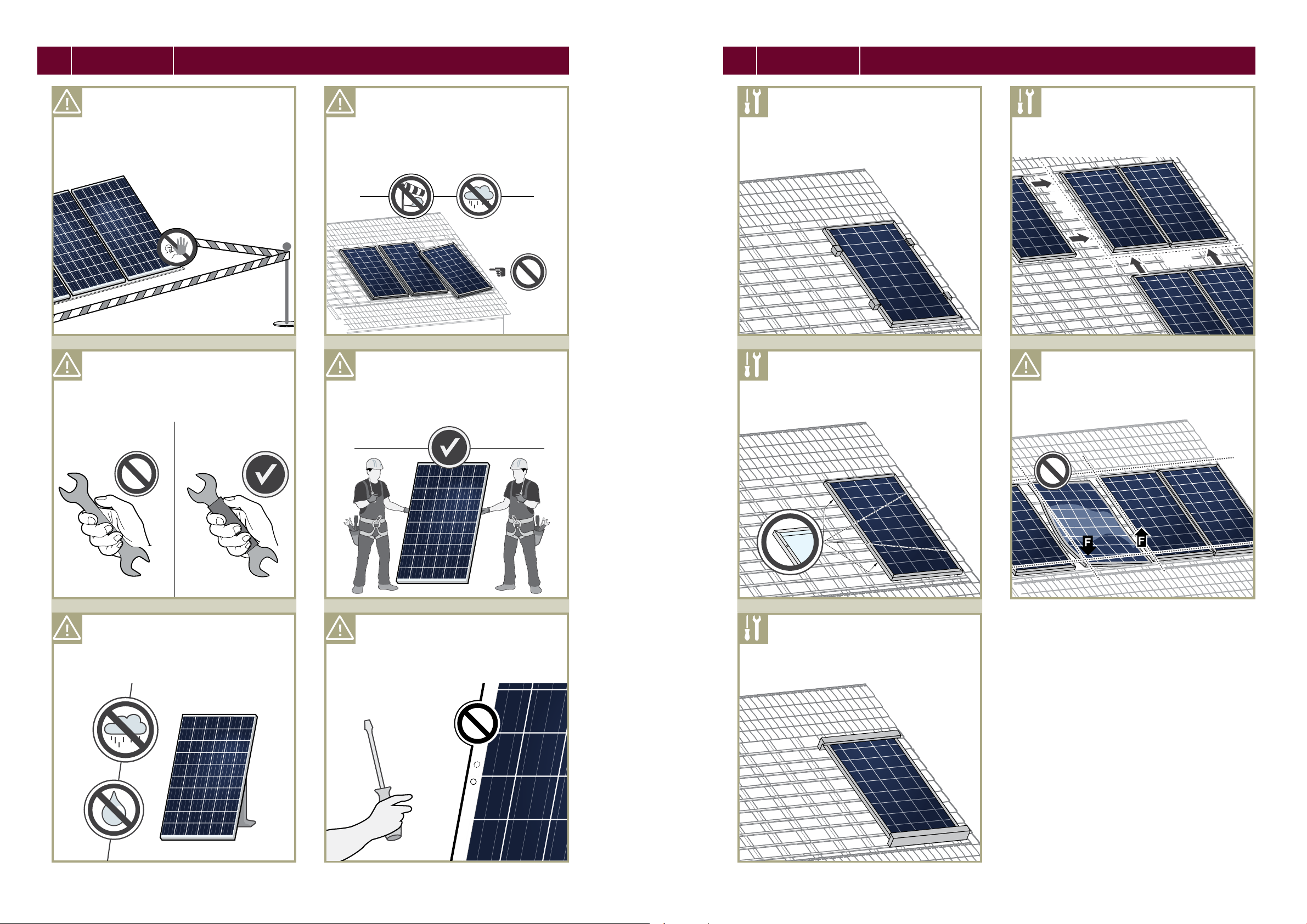
3 INSTALLATION
3.2 Preparation of installation
3 INSTALLATION
3.3 Module installation
DANGER! Risk of fatal injury due to electric
shock!
Ä Block off the installation zone.
Ä Keep children and unauthorized
individuals away from the solar power
system.
DANGER! Risk of fatal injury due to electric
shock!
Ä Only use dry, insulated tools.
WARNING! Risk of injury due to falling mod-
ules!
Ä Secure modules during installation.
Ä Do not install modules in windy or wet
weather.
Ä Do not carry out the installation alone.
Option 1:
Ä Fasten the module with 4 clamps in the
specied clamping range, see Fig. 3, p.
8.
Ä Tighten clamps according to
manufacturer’s instructions.
Option 2:
Ä Install the module at the 4 mounting
points, see Fig. 3, p. 8.
Ä Tighten clamps according to
manufacturer’s instructions.
Ä Maintain an interval of at least 10 mm
between two modules.
10mm
10mm
NOTE! Module damage may occur!
Ä Do not subject modules to mechanical
tension. Max. torsion 10 mm/m.
DANGER! Risk of fatal injury due to electric
shock!
Ä Ensure that modules and tools are not
subject to moisture or rain at any time
during installation.
14 15INSTALLATION AND OPERATION MANUAL SOLAR MODULES GENERATION 3 (G3) – HANWHA Q CELLS AUSTRALIA PTY LTD
• Only install undamaged modules and
components.
Ä Do not drill any other holes.
Option 3:
Ä Install the module using mounting
proles, Fig. 3, p. 8.
INSTALLATION AND OPERATION MANUAL SOLAR MODULES GENERATION 3 (G3) – HANWHA Q CELLS AUSTRALIA PTY LTD
1514

4 ELECTRICAL CONNECTION
4.1 Safety
4 ELECTRICAL CONNECTION
4.2 Electrical installation safety
DANGER!
Risk of fatal injury due to electric shock!
When disconnecting an electric circuit carrying direct
current, electric arcs can occur that may result in
life-threatening injuries.
Ä Do NOT unplug the cable when under load.
Ä Do NOT connect any exposed cable ends.
Ä Do NOT touch the poles at the same time.
A solar module generates electrical current and voltage
even at a low intensity of illumination. Sparks and electric
arcs may result from the separation of a closed circuit.
These can result in life-threatening injuries. The danger
increases when several modules are connected in series.
Ä Please ensure that the entire open circuit voltage is
active even at low levels of solar irradiation.
Ä Please follow the valid national regulations and safety
guidelines for the installation of electrical devices and
systems.
Ä
Please make sure to take all necessary safety precautions.
With module or phase voltages of more than 120 V, the
extra-low voltage range is exceeded.
Ä
Carry out work on the inverter and the wiring with extreme
caution.
Ä
Ensure that the modules are disconnected at the inverter
prior to separation.
Ä Be sure to observe the specied time intervals after
switching off the inverter. High-voltage components
need time to discharge.
DANGER! Risk of fatal injury due to electric
shock!
Ä Never open the junction box.
Ä Do not remove bypass diodes.
DANGER! Risk of fatal injury due to electric
shock!
Ä Never touch live contacts with bare
hands.
Ä Do not touch the poles at the same time.
DANGER! Risk of fatal injury due to electric
shock!
Ä Ensure correct polarity.
DANGER! Risk of fatal injury due to electric
shock!
Ä Be sure to maintain the time intervals as
specied by the inverter manufacturer
between switching off the inverter and
beginning any further work.
DANGER! Risk of fatal injury due to electric
shock!
Ä Never unplug the cable when under load.
1. Switch off the inverter.
AUS
2. Cover the modules to be disconnected.
DANGER! Risk of fatal injury due to electric
shock!
Ä Only use dry, insulated tools for electrical
work.
16 17INSTALLATION AND OPERATION MANUAL SOLAR MODULES GENERATION 3 (G3) – HANWHA Q CELLS AUSTRALIA PTY LTD
DANGER! Risk of fatal injury due to electric
shock!
Ä Insulate any exposed cable ends.
Ä Only connect cables with plugs.
3. Switch off the DC circuit breaker.
Ä Disconnect plugs by the use of
appropriate and qualied tools of the
manufacturer Tyco or Multicontact
(adequate for PV4 plug type).
INSTALLATION AND OPERATION MANUAL SOLAR MODULES GENERATION 3 (G3) – HANWHA Q CELLS AUSTRALIA PTY LTD
1716

4 ELECTRICAL CONNECTION
4.3 Connection of modules
4 ELECTRICAL CONNECTION
4.4 After installation
Ä Use solar cables for the connection at
the junction box outlet.
Ä Use the same, inverter-compatible plugs.
SOLAR
DANGER! Risk of fatal injury due to electric
shock!
Ä Ensure that all electrical components are
in a proper, dry, and safe condition.
NOTE! Module damage may occur!
Ä Ensure that the cabling is not under
stress.
Ä Ensure that the cables do not run
between module and subconstruction
(danger of pinch).
Ä Do not connect modules with different
orientations or angles of inclination in
the same string.
Ä Ensure that all necessary safety and
functional tests have been carried out
according to current industry standards.
Ä Integrate the system into the existing
lightening protection system in
accordance with the applicable local
regulations.
NOTE! Module damage may occur!
Ä Ensure that the plug connections are not
level with a water-channeling surface.
WARNING! Fire Risk!
Ä Do not use light concentrators (e.g.
mirrors or lenses).
Ä Ensure for a tight connection between
the plugs. Plugs click together audibly.
• A module with 1,160 mm long cable can
be wired as a "2nd next neighbor".
"2nd next neighbor" - Wiring without a
return cable.
Standard wiring with a return cable.
1
Inverter
click
Inverter
18 19INSTALLATION AND OPERATION MANUAL SOLAR MODULES GENERATION 3 (G3) – HANWHA Q CELLS AUSTRALIA PTY LTD
2
Ä Ensure that cables are protected from
abrasion, tension, compression and
cutting forces in full accordance with
AS / NZS 3000.
INSTALLATION AND OPERATION MANUAL SOLAR MODULES GENERATION 3 (G3) – HANWHA Q CELLS AUSTRALIA PTY LTD
1918

5 GROUNDING
6 FAULTS AND DEFECTS
8 CLEANING AND MAINTENANCE
Protective Grounding
Ä
The modules must be grounded in accordance with the
local statutory regulations.
Functional grounding
• When using an installation tilt of < 5° a functional
grounding at the negative generator conncetion must
be implemented.
Ä Ensure that the difference of potential between the
negative generator connection and the PE(N) of every
MPP tracker of the respective inverters is 0 V.
Ä Follow the directions of the inverter manufacturer.
Ä Only use inverters which include lincensed grounding
kits.
DANGER!
Risk of fatal injury due to electric shock!
Ä Do not attempt to x any problems yourself (e.g.,
glass cracks, damaged cables).
Ä Please contact an installer or Q CELLS Technical
Customer Service Department.
7 DISPOSAL
Ä Do not disconnect modules yourself.
Ä Please commission a trade specialist.
Dispose of modules in accordance with the local disposal
Ä
regulations.
Q CELLS solar modules are known for a long operating
life and minimal maintenance effort and expense. Dirt
and grime are usually washed away by rain. If the module
is fully or partially shaded by dirt or debris (e.g., plants,
bird droppings), it needs to be cleaned to prevent a loss
of performance.
Maintenance
Ä
The system should be inspected by an installer annually
to check the following:
•
all system components sit securely and are corrosion
free.
•
the connection is secure and all electrical components
are clean and undamaged.
Cleaning
WARNING!
Risk of injury due to hot and
live modules!
Ä Only clean modules that have cooled down.
Ä Do not carry or wear any electrically conductive parts.
NOTE! Module damage may occur!
Ä Do not clean modules with water if there
is a risk of frost.
0°
Ä Remove dirt with lukewarm water, a
broom, or a soft cloth.
Ä Do not use tensides, scrapers, or any
high-pressure water cleaning equipment.
WARNING!
Risk of falling due to unsecured
access!
Ä Never access the installation area alone or without
taking adequate security precautions.
Ä Please commission a trade specialist.
Clean the modules as follows:
NOTE!
Module surface damage may occur!
Ä Remove snow and ice without force (e.g. with a very
soft broom)
Ä Do not scratch off dirt.
Ä Rinse dirt off with lukewarm water (dust, leaves, etc.)
Ä Use a soft cellulose cloth (kitchen roll) or sponge to
carefully wipe off stubborn dirt. Do not use micro eece
wool or cotton cloths.
Ä
Use an alcohol based glass cleaner. Do not use abrasive
detergents or tensides.
Isopropyl alcohol (IPA) can be used selectively to remove
stubborn dirt and stains within one hour after emergence.
Ä Please follow the safety guidelines provided by the IPA
manufacturer.
Ä Do not let IPA run down between the module and the
frame or into the module edges.
Ä Free the substructure from any dirt and
debris (leaves, bird nests, etc.).
20 21INSTALLATION AND OPERATION MANUAL SOLAR MODULES GENERATION 3 (G3) – HANWHA Q CELLS AUSTRALIA PTY LTD
INSTALLATION AND OPERATION MANUAL SOLAR MODULES GENERATION 3 (G3) – HANWHA Q CELLS AUSTRALIA PTY LTD
21

ContaCt
HanwHa Q CELLS auStraLia Pty Ltd
Level 14, 20 Berry Street
North Sydney
NSW 2060
Australia
tEL +61 (0)2 90 16 – 3033
FaX +61 (0)2 690 16 – 3032
EMaiL q-cells-australia@q-cells.com
wEB www.q-cells.com.au
Subject to change without notice. © Hanwha Q CELLS GmbH Installation manual G3 modules_2015-02_Rev06_AU
 Loading...