

Page 1
I
QBOX-1200 User’s Manual
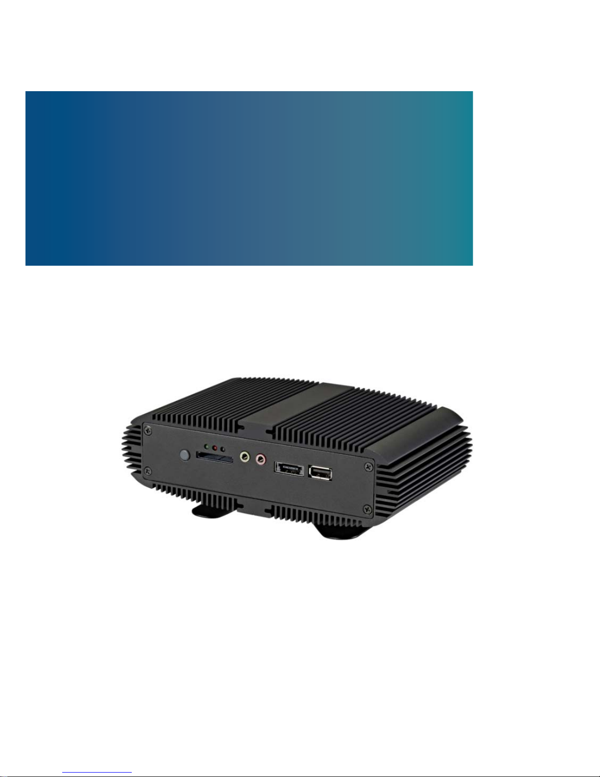
QBOX-1200
Fanless Nettop with Intel® Pineview Processor
User’s Guide
Page 2

II
QBOX-1200 User’s Manual
This page intentionally left blank.
Page 3

3
QBOX-1200 User’s Manual
Content
Content ....................................................................................................................... 3
Figures ....................................................................................................................... 4
Tables ......................................................................................................................... 4
Safety Instructions ...................................................................................................... 5
Before You Begin ............................................................................... 5
When Working Inside a Computer ..................................................... 6
Preventing Electrostatic Discharge .................................................... 6
Instructions for Lithium Battery ........................................................... 7
Voltage Ratings .................................................................................. 7
Preface ....................................................................................................................... 8
How to Use This Guide ...................................................................... 8
Unpacking .......................................................................................... 8
Regulatory Compliance Statements ................................................... 8
Warranty Policy .................................................................................. 9
Maintaining Your Computer .............................................................. 10
Chapter 1 Introduction ........................................................................................... 13
Overview .......................................................................................... 13
System tour ...................................................................................... 15
Mechanical Dimensions ................................................................... 19
Chapter 2 Getting Started
...................................................................................... 20
Setting up your PC ........................................................................... 20
Connecting Desktop Bracket on QBox-1200 .................................... 23
Mounting your PC to a Monitor ......................................................... 24
Chapter 3 AMI BIOS Setup .................................................................................... 27
Overview .......................................................................................... 27
Main Menu ....................................................................................... 28
Configuration Menu .......................................................................... 29
Boot Menu ........................................................................................ 31
Security Menu .................................................................................. 31
Exit Menu ......................................................................................... 33
Chapter 4 Driver Installation
.................................................................................. 34
Page 4

4
QBOX-1200 User’s Manual
Figures
Figure 1 Front Panel ................................................................................................. 15
Figure 2 Rear Panel ................................................................................................. 17
Figure 3 Mechanical Figures .................................................................................... 19
Figure 4 Connect the VGA cable .............................................................................. 20
Figure 5 Connecting USB mouse & keyboard .......................................................... 21
Figure 6 Network cable with RJ45 connector ........................................................... 21
Figure 7 Turing on the system
.................................................................................. 22
Figure 8 Desktop Bracket Assembly ........................................................................ 23
Figure 9 Desktop Bracket on QBox-1200 ................................................................. 23
Figure 10 VESA Mounting (1) ................................................................................... 24
Figure 11 VESA Mounting (2) ................................................................................... 24
Figure 12 Assemble VESA Mounting Kit
.................................................................. 25
Figure 13 Sliding VESA Mounting Kit onto QBox-1200 ............................................ 25
Figure 14 Rear View of QBox-1200 .......................................................................... 26
Figure 15 Front View of QBox-1200 ......................................................................... 26
Tables
Table 1 QBOX-1200 product specifications .............................................................. 14
Table 2 BIOS Main Menu ......................................................................................... 28
Table 3 Configuration ............................................................................................... 29
Table 4 Power management Settings
....................................................................... 29
Table 5 Hardware Health Configuration .................................................................... 31
Table 6 Boot Menu ................................................................................................... 31
Table 7 Security Menu .............................................................................................. 32
Table 8 Exit Menu ..................................................................................................... 33
Page 5
5
QBOX-1200 User’s Manual
Safety Instructions
Before Y ou Begin
Before handling the product, read the instructions and safety guidelines on the
following pages to prevent damage to the product and to ensure your own personal
safety. Refer to the “Advisories” section in the Preface for advisory conventions used
in this user’s guide, including the distinction between Warnings, Cautions, Important
Notes, and Notes.
Always use caution when handling/operating a computer. Only qualified,
experienced, authorized electronics service personnel should access the
interior of a computer. The power supplies produce high voltages and
energy hazards, which can cause bodily harm.
Use extreme caution when installing or removing components. Refer to the
installation instructions in this user’s guide for precautions and procedures.
If you have any questions, please contact with your dealer for Post-Sales
Technical Support.
Access can only be gained by service persons or by users who have
been instructed about the reasons for the restrictions applied to the
location and about any precautions that shall be taken; and access is
through the use of a tool or lock and key, or other means of security,
and is controlled by authority responsible for the location.
WARNING
High voltages are present inside the chassis when the unit’s power cord is plugged into
an electrical outlet. Turn off system power, turn off the power supply, and then
disconnect the power cord from its source before removing the chassis cover. Turning off
the system power switch does not remove power to components.
The product chassis may be hot when the system is working. Please
do not touch the surface before turn off the system power and wait
for about 5 minutes until the system cools down.
Page 6

6
QBOX-1200 User’s Manual
When Working Inside a Computer
Before taking covers off a computer, perform the following steps:
1. Turn off the computer and any peripherals.
2. Disconnect the computer and peripherals from their power sources or
subsystems to prevent electric shock or system board damage. This does not
apply when hot swapping parts.
3. Follow the guidelines provided in “Preventing Electrostatic Discharge” on the
following page.
4. Disconnect any telephone or telecommunications lines from the computer.
In addition, take note of these safety guidelines when appropriate:
To help avoid possible damage to system boards, wait five seconds after
turning off the computer before removing a component, removing a system
board, or disconnecting a peripheral device from the computer.
When you disconnect a cable, pull on its connector or on its strain-relief loop,
not on the cable itself. Some cables have a connector with locking tabs. If you
are disconnecting this type of cable, press in on the locking tabs before
disconnecting the cable. As you pull connectors apart, keep them evenly
aligned to avoid bending any connector pins. Also, before connecting a cable,
make sure both connectors are correctly oriented and aligned.
CAUTION
Do not attempt to service the system yourself except as explained in this user’s guide.
Follow installation and troubleshooting instructions closely.
Preventing Electrostatic Discharge
Static electricity can harm system boards. Perform service at an ESD workstation
and follow proper ESD procedure to reduce the risk of damage to components. We
strongly encourage you to follow proper ESD procedure, which can include wrist
straps and smocks, when servicing equipment.
You can also take the following steps to prevent damage from electrostatic
discharge (ESD):
When unpacking a static-sensitive component from its shipping carton, do not
remove the component’s antistatic packing material until you are ready to install
Page 7

7
QBOX-1200 User’s Manual
the component in a computer. Just before unwrapping the antistatic packaging,
be sure you are at an ESD workstation or grounded. This will discharge any
static electricity that may have built up in your body.
When transporting a sensitive component, first place it in an antistatic container
or packaging.
Handle all sensitive components at an ESD workstation. If possible, use
antistatic floor pads and workbench pads.
Handle components and boards with care. Don’t touch the components or
contacts on a board. Hold a board by its edges or by its metal mounting bracket.
Do not handle or store system boards near strong electrostatic, electromagnetic,
magnetic, or radioactive fields.
Instructions for Lithium Battery
WARNING
Danger of explosion when battery is replaced with incorrect type. Only replace
with the same or equivalent type recommended by the manufacturer.
Do not dispose of lithium batteries in domestic waste. Dispose of the battery
according to the local regulations dealing with the disposal of these special
materials (e.g. to the collecting points for disposal of batteries)
Voltage Ratings
The external power adaptor of the QBOX-1200 has the following voltage ratings:
Input: 100-240 VAC, 50-60 Hz
Output: 40W, +19Vdc, 2.1A
Page 8

8
QBOX-1200 User’s Manual
Preface
How to Use This Guide
This guide is designed to be used as step-by-step instructions for installation, and as
a reference for operation, troubleshooting, and upgrades.
NOTE
Driver downloads and additional information are available under Downloads on
dealer’s website
Unpacking
When unpacking, follow these steps:
1. After opening the box, save it and the packing material for possible future
shipment.
2. Remove all items from the box. If any items listed on the purchase order
are missing, notify your customer service immediately.
3. Inspect the product for damage. If there is damage, notify your customer
service immediately. Refer to “Warranty Policy” for the return procedure.
Regulatory Compliance Statement s
This section provides the FCC compliance statement for Class A devices.
FCC Compliance Statement:
This equipment has been tested and found to comply with limits for a Class A digital
device, pursuant to Part 15 of the FCC rules. These limits are designed to provide
reason able protection against harmful interference in residential installations. This
equipment generates, uses, and can radiate radiofrequency energy, and if not
installed and used in accordance with the instructions, may cause harmful
interference to radio communications. However, there is no guarantee that
interference will not occur in a particular installation. If this equipment does cause
interference to radio or television equipment reception, which can be determined by
Page 9

9
QBOX-1200 User’s Manual
turning the equipment off and on, the user is encouraged to try to correct the
interference by one or more of the following measures:
Reorient or relocate the receiving antenna.
Increase the separation between the equipment and receiver.
Connect the equipment to an outlet on a circuit different from that to which the
receiver is connected.
Consult the dealer or an experienced radio/TV technician for help.
Changes or modifications not expressly approved by your dealer could void the
user's authority to operate the equipment.
NOTE
The assembler of a personal computer system may be required to test the system
and/or make necessary modifications if a system is found to cause harmful
interference or to be noncompliant with the appropriate standards for its intended use.
Warranty Policy
Limited Warranty
Please consult your distributor for warranty verification.
The limited warranty is void if the product has been subjected to alteration, neglect,
misuse, or abuse; if any repairs have been attempted by anyone other than your
manfacturer or its authorized agent; or if the failure is caused by accident, acts of
God, or other causes beyond the control of your dealer or the manufacturer. Neglect,
misuse, and abuse shall include any installation, operation, or maintenance of the
product other than in accordance with the user’s guide.
No agent, dealer, distributor, service company, or other party is authorized to change,
modify, or extend the terms of this Limited Warranty in any manner whatsoever. Your
manufacturer reserves the right to make changes or improvements in any product
without incurring any obligation to similarly alter products previously purchased.
Return Procedure
For any Limited Warranty return, please contact with your dealer.
All product(s) returned to your dealer for service or credit must be accompanied by a
Return Material Authorization (RMA) Number. Freight on all returned items must be
prepaid by the customer who is responsible for any loss or damage caused by
Page 10

10
QBOX-1200 User’s Manual
common carrier in transit. Returns for Warranty must include a Failure Report for
each unit, by serial number(s), as well as a copy of the original invoice showing the
date of purchase.
To reduce risk of damage, returns of product must be in a shipping container. If the
original container has been lost or damaged, new shipping containers may be
obtained from your dealer’s Customer Service at a nominal cost.
We own all parts removed from repaired products. We use new and reconditioned
parts made by various manufacturers in performing warranty repairs and building
replacement products. If your dealer repairs or replaces a product, its warranty term
is not extended.
Shipments not in compliance with this Limited Warranty Return Policy will not be
accepted by us.
Limitation of Liability
In no event shall your dealer be liable for any defect in hardware, software, loss, or
inadequacy of data of any kind, or for any direct, indirect, incidental, or
consequential damages in connection with or arising out of the performance or use
of any product furnished hereunder. Our liability shall in no event exceed the
purchase price of the product purchased hereunder. The foregoing limitation of
liability shall be equally applicable to any service provided by us or its authorized
agent.
Maintaining Your Computer
Environmental Factors
Temperature
The ambient temperature within an enclosure may be greater than room
ambient temperature. Installation in an enclosure should be such that the
amount of air flow required for safe operation is not compromised.
Consideration should be given to the maximum rated ambient temperature.
Overheating can cause a variety of problems, including premature aging and
failure of chips or mechanical failure of devices.
If the system has been exposed to abnormally cold temperatures, allow a
two-hour warm-up period to bring it up to normal operating temperature before
turning it on. Failure to do so may cause damage to internal components,
particularly the hard disk drive.
Humidity
Page 11

11
QBOX-1200 User’s Manual
High-humidity can cause moisture to enter and accumulate in the system. This
moisture can cause corrosion of internal components and degrade such
properties as electrical resistance and thermal conductivity. Extreme moisture
buildup inside the system can result in electrical shorts, which can cause
serious damage to the system.
Buildings in which climate is controlled usually maintain an acceptable level of
humidity for system equipment. However, if a system is located in an unusually
humid location, a dehumidifier can be used to maintain the humidity within an
acceptable range. Refer to the “Specifications” section of this user’s guide for
the operating and storage humidity specifications.
Altitude
Operating a system at a high altitude (low pressure) reduces the efficiency of
the cooling fans to cool the system. This can cause electrical problems related
to arcing and corona effects. This condition can also cause sealed components
with internal pressure, such as electrolytic capacitors, to fail or perform at
reduced efficiency.
Power Protection
The greatest threats to a system’s supply of power are power loss, power spikes,
and power surges caused by electrical storms, which interrupt system operation
and/or damage system components. To protect your system, always properly
ground power cables and one of the following devices.
Surge Protector
Surge protectors are available in a variety of types and usually provide a level
of protection proportional with the cost of the device. Surge protectors prevent
voltage spikes from entering a system through the AC power cord. Surge
protectors, however, do not offer protection against brownouts, which occur
when the voltage drops more than 20 percent below the normal AC line voltage
level.
Line Conditioner
Line conditioners go beyond the overvoltage protection of surge protectors.
Line conditioners keep a system’s AC power source voltage at a fairly constant
level and, therefore, can handle brownouts. Because of this added protection,
line conditioners cost more than surge protectors. However, line conditioners
cannot protect against a complete loss of power.
Page 12

12
QBOX-1200 User’s Manual
Uninterruptible Power Supply
Uninterruptible power supply (UPS) systems offer the most complete protection
against variations on power because they use battery power to keep the server
running when AC power is lost. The battery is charged by the AC power while it
is available, so when AC power is lost, the battery can provide power to the
system for a limited amount of time, depending on the UPS system.
UPS systems range in price from a few hundred dollars to several thousand
dollars, with the more expensive unit s allowing you to run larger systems for a
longer period of time when AC power is lost. UPS systems that provide only 5
minutes of battery power let you conduct an orderly shutdown of the system,
but are not intended to provide continued operation. Surge protectors should be
used with all UPS systems, and the UPS system should be Underwriters
Laboratories (UL) safety approved.
Page 13

Chapter 1
13
QBOX-1200 User’s Manual
Chapter 1
Introduction
Overview
The QBOX-1200 is a fan-less Box PC that is ideal for space critical applications.
This embedded hardware platform is designed with Intel® Dual-core D510
Processor which provides with excellent performance enabled by next- generation
Technology. The system is supported with Intel® NM10 chipset, and DDR2 667
SODIMM up to 2GB. Featured are a 2.5” SATA hard drive bay, eSATA/USB, GbE,
USB 2.0, VGA, Mic-In, Audio-out, 3-in-1 SD/MCC/MS Card Reader and optional 1x
802.11n or 3G/3.5G half size mini card. The QBOX-1200 provides high reliability
rugged case not only for great protection from EMI, cold and heat, but also
integrated with passive cooling design for quiet fan-less operation such as Digital
Signage, Transportation, Surveillance, and Thin Client.
Checklist
QBOX-1200
Power Adapter
Power Cord
Driver CD
Quick installation Guide
Desktop Bracket
Optional VESA Mounting Kit
Features
Fan-less Design Compact Sized
Intel® Atom Dual-core D510 Processor
Intel® NM10
Support DDR2 667 SODIMM up to 2GB
Support 1x GbE, 1x 2.5” SATA HDD, 1x eSATA/USB, 3x USB, VGA, Mic-In,
Audio-out, and 3-in-1 SD/MCC/MS Card Reader
Optional 1x 802.11n or 3G/3.5G half size mini card
Page 14

Chapter 1
14
QBOX-1200 User’s Manual
Product Specifications
Dimensions
184 x 56 x 110 mm (WxHxD)
Weight
1600 g
CPU/ Chipset
Intel® Atom D510 Processor , NM10
RAM
1 x DDR2 667 SODIMM up to 2GB
Storage
1 x 2.5” SATA HDD
1 x 3-in-1 SD/MCC/MS Card Reader
Front IO
1x Phone Jack for Line-Out
1x Phone Jack for MIC-In
1x Push button for power on/off
1x POWER LED (Green)
1x HDD LED (Red)
1x Wifi LED (Blue)
1x USB2.0
1x eSATA and USB combo connector (Power eSATA)
3-in-1 SD/MCC/MS Card Reader
Rear IO
1x DC JACK for DC19V input
1x D-SUB 15 connector
2x USB 2.0
1x RJ-45, GbE port
1x Push button for clear CMOS
Wireless LAN
Optional Mini PCIe WI-FI Card
Cooling
Fanless and Internal Heat Pipes
Power Unit
Input: 100-240 VAC, 50-60 Hz
Output: 40W, +19Vdc, 2.1A
Temperature /
Humidity
Operating: 0°C to 40°C, 0%-90%, non-condensing
Storage: -20°C to 80°C, 0%-90%, non-condensing
Mounting
Desktop Bracket, VESA-mount (optional)
Certifications
CE, FCC Class A
Table 1 QBOX-1200 product specifications
Page 15
Chapter 1
15
QBOX-1200 User’s Manual
System tour
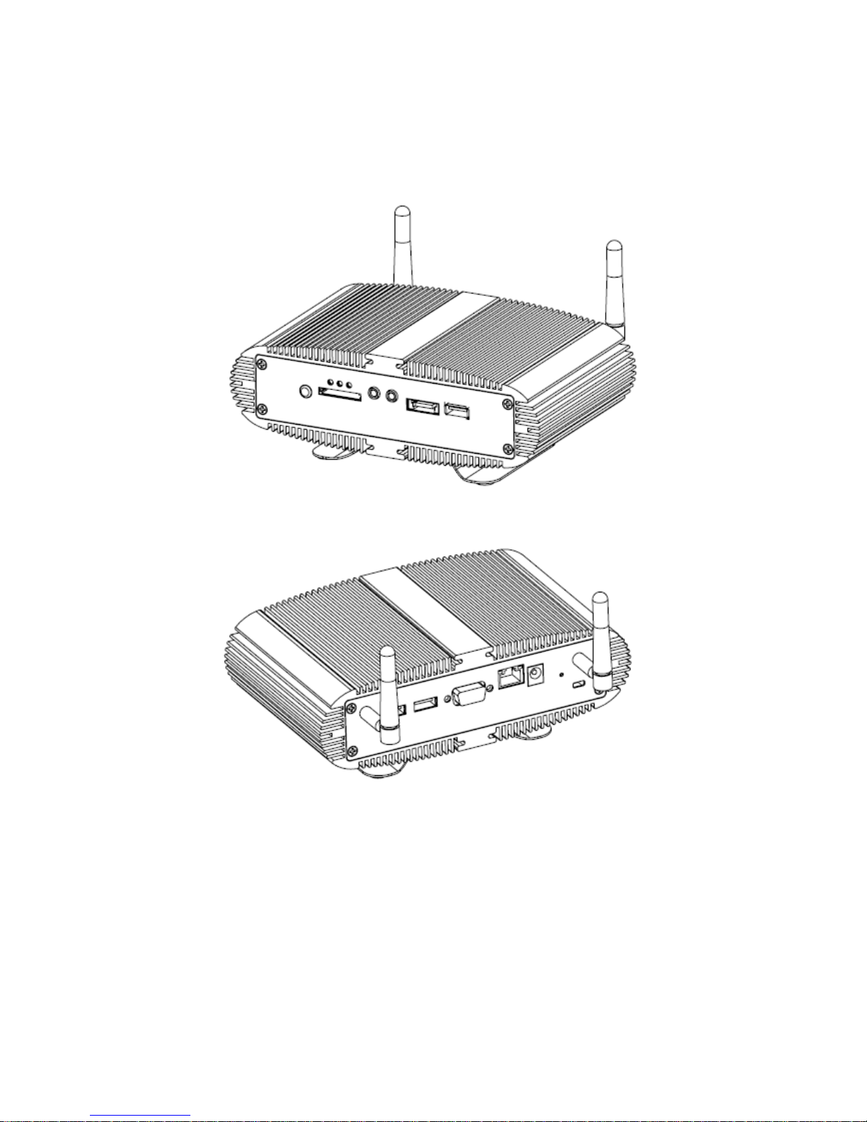
Refer to the figures below to identify the components of the system.
Front Panel
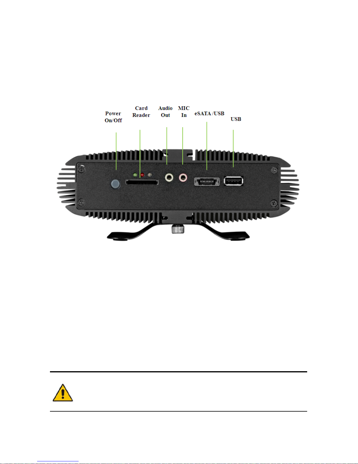
Figure 1 Front Panel
Power Switch
The power push button allows powering ON and OFF the system.
Power LED (Green)
The power LED will light when the PC is power-on.
HDD LED (Red)
The hard disk LED blinks when data is being written into or read from the HDD.
WiFi LED (Blue)
When the data is Transferring, the WiFi LED will blink.
CAUTION
This connector do not support hot-swapping. Users should not connect or
disconnect their eSATA/USB devices from PC when the system is working.
Page 16

Chapter 1
16
QBOX-1200 User’s Manual
Card Reader
3-in-1 SD/MCC/MS Card Reader
Audio Out
The stereo headphone jack is used to connect the system’s audio out signal to
amplified speakers or headphones.
MIC-IN
The microphone jack is designed to connect the microphone used for video
conferencing, voice narrations, or simple audio recordings.
Combo Connector
1x eSATA and USB combo connector (Power eSATA)
USB
The USB (Universal Serial Bus) port is compatible with USB devices such as
keyboards, mouse devices, cameras, and hard disk drives. USB allows many
devices to run simultaneously on a single computer, with some peripheral acting as
additional plug-in sites or hubs.
Page 17
Chapter 1
17
QBOX-1200 User’s Manual
Rear Panel
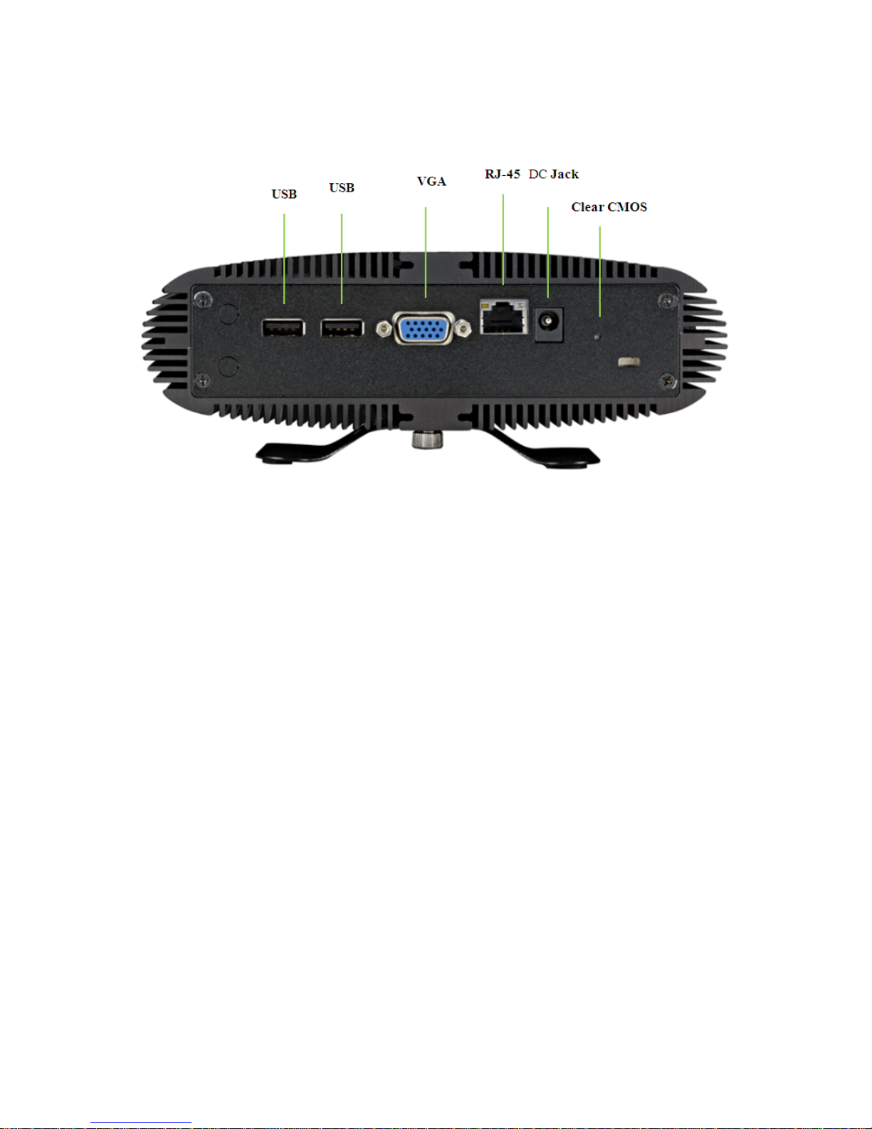
Figure 2 Rear Panel
USB
The USB (Universal Serial Bus) port is compatible with USB devices such as
keyboards, mouse devices, cameras, and hard disk drives. USB allows many
devices to run simultaneously on a single computer, with some peripheral
acting as additional plug-in sites or hubs.
VGA
D-Sub 15 pin VGA connector for display output
Ethernet
The eight-pin RJ-45 LAN port supports a standard Ethernet cable for
connection to a local network.
DC Jack
The supplied power adapter converts AC power to DC for use with this jack.
Power supplied through this jack supplies power to the PC. To prevent damage
to the PC, always use the supplied power adapter.
Page 18

Chapter 1
18
QBOX-1200 User’s Manual
Clear CMOS Button
To clear the CMOS, use the tip of a pen to press the button briefly (for less than
three seconds).
Page 19
Chapter 1
19
QBOX-1200 User’s Manual
Mechanical Figures
Dimension: 184 x 56 x 110 mm (W x H x D)
Figure 3 Mechanical Figures
Page 20
20
QBOX-1200 User’s Manual
Chapter 2
Getting Started
Setting up your PC
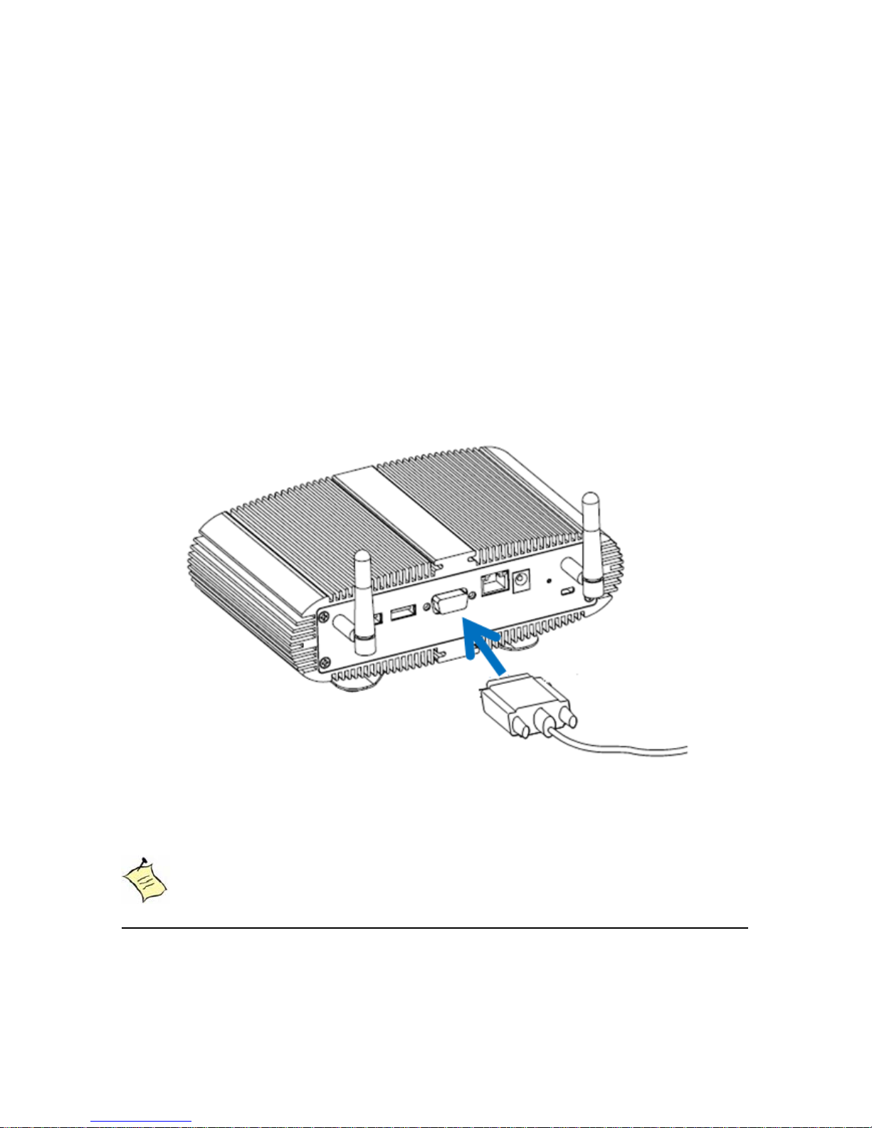
Connect the monitor, mouse and keyboard
Connecting the monitor
Connect the VGA cable from your display to the VGA port.
Figure 4 Connect the VGA cable
NOTE
When the system reboots without connecting the VGA, there might be no
image on screen when you insert the VGA cable. Please
pressing <Ctrl>+<Alt>+<F4> simultaneously to show the image on screen.
Page 21
Chapter 3
21
QBOX-1200 User’s Manual
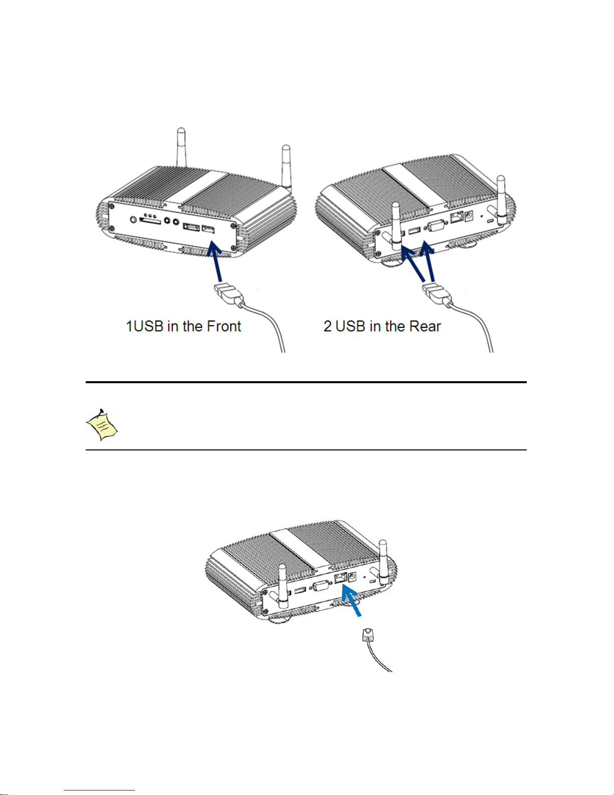
Connecting USB mouse & keyboard
Your QBOX-1200 does not come with a keyboard and mouse, but you can use any
USB keyboard or mouse with your computer.
Figure 5 Connecting USB mouse & keyboard
NOTE
Using a third-party USB mouse or keyboard may require software drivers.
Check the manufacturer’s website for the latest software drivers.
Connecting to a network device
Connect one end of a network cable to the LAN port on the system rear panel and
the other end to a hub or switch.
Figure 6 Network cable with RJ45 connector
Page 22
Chapter 3
22
QBOX-1200 User’s Manual
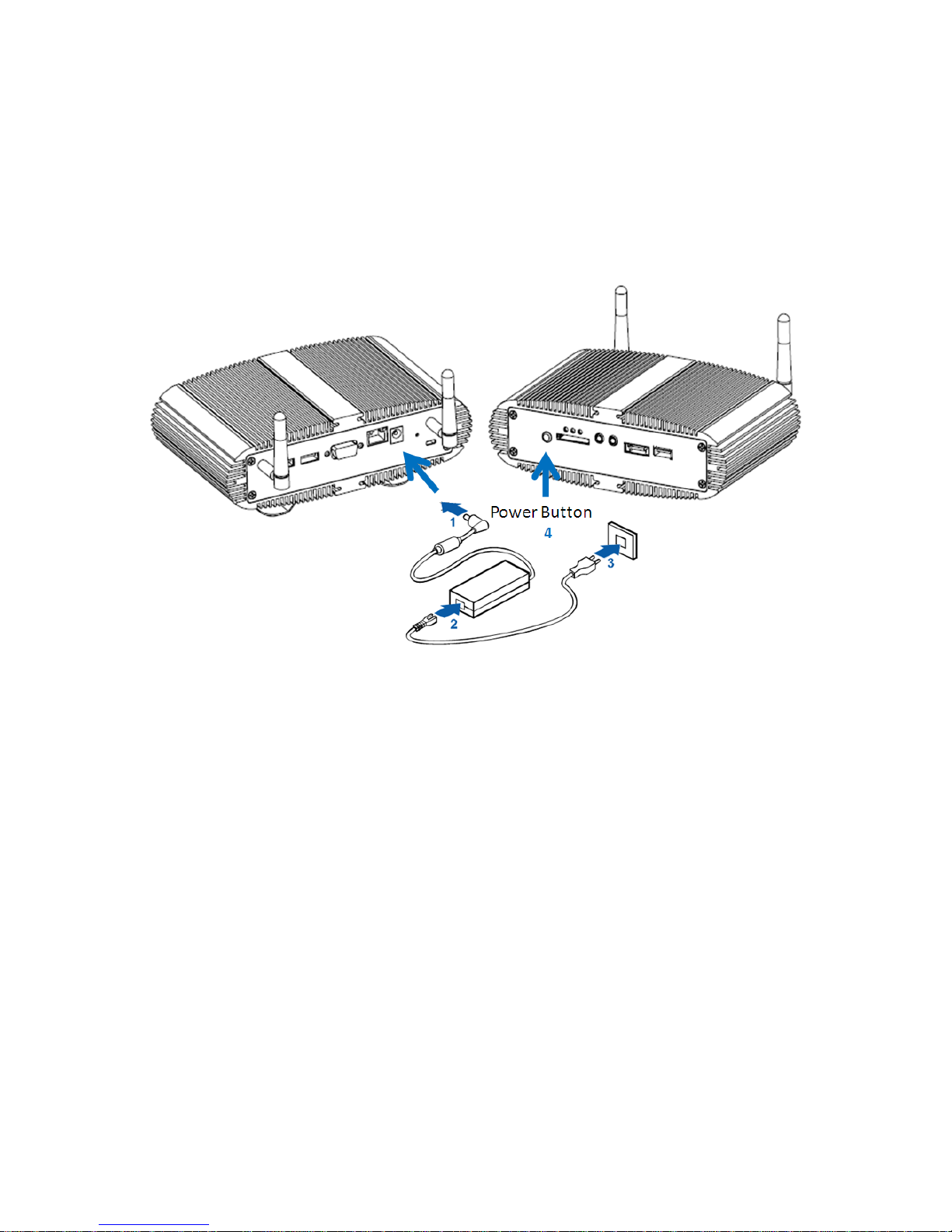
Turning on the system
1. Connect the power adapter cable to the DC jack (DC IN) of the QBOX-1200
2. Connect the power cable to the power adapter
3. Connect the power cable to a power outlet
4. Press the power switch on the front panel to turn on the system
Figure 7 Turing on the system
Page 23
Chapter 3
23
QBOX-1200 User’s Manual
Connecting Desktop Bracket on QBox-1200
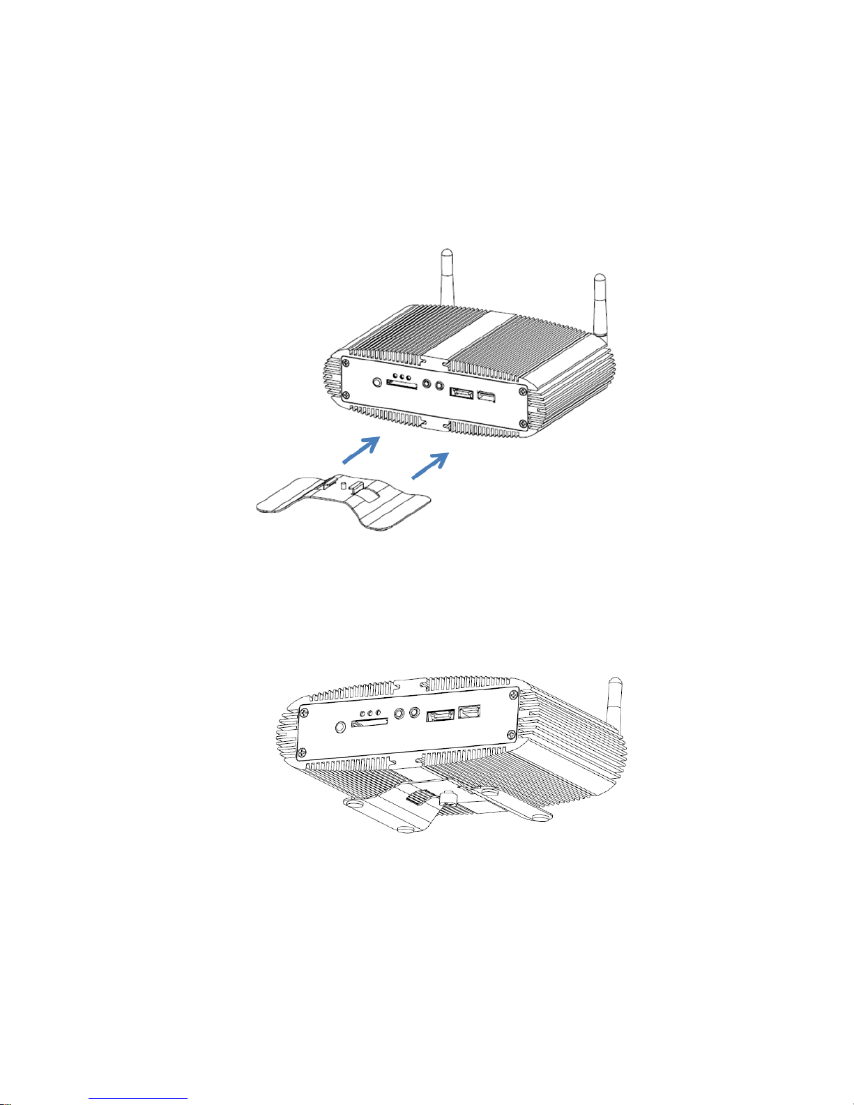
1. By sliding the desktop bracket onto the rails of QBox-1200 on the bottom in
either ways from front side or back side.
Figure 8 Desktop Bracket Assembly
2. Then tighten the screw as shown below.
Figure 9 Desktop Bracket on QBox-1200
Page 24
Chapter 3
24
QBOX-1200 User’s Manual
Mounting your PC to a monitor
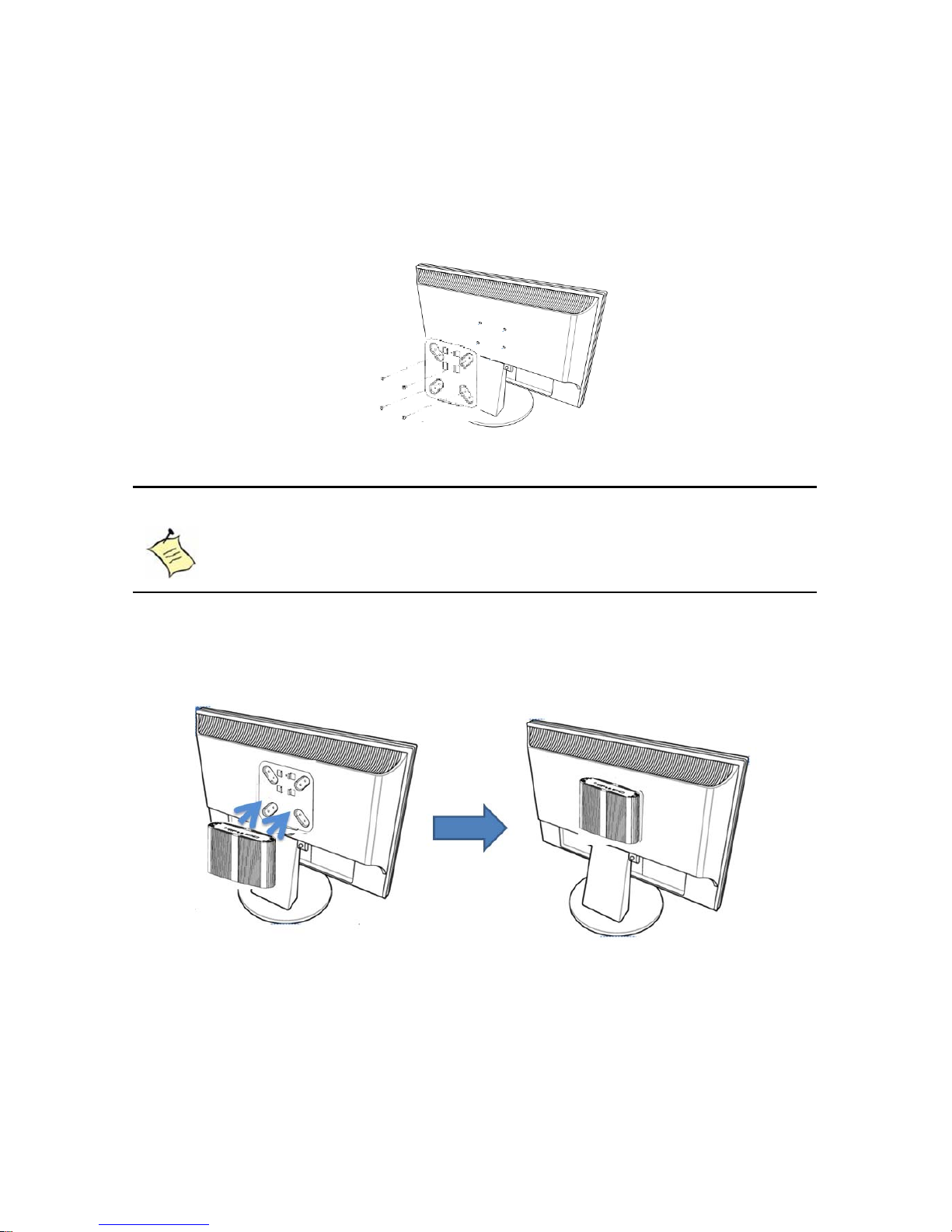
1. Secure the VESA mounting kit to your monitor with four screws.
Figure 10 VESA mounting (1) (Optional)
NOTE
To fasten the metal shelf, your monitor must comply with VESA75 or
VESA100 standard.
1. Place the QBox-1200 on the VESA mounting kit and make sure the
computer is fitting well on the bracket.
Figure 11 VESA mounting (2) (Optional)
Page 25
Chapter 3
25
QBOX-1200 User’s Manual
Assemble VESA Mounting Kit onto QBox-1200
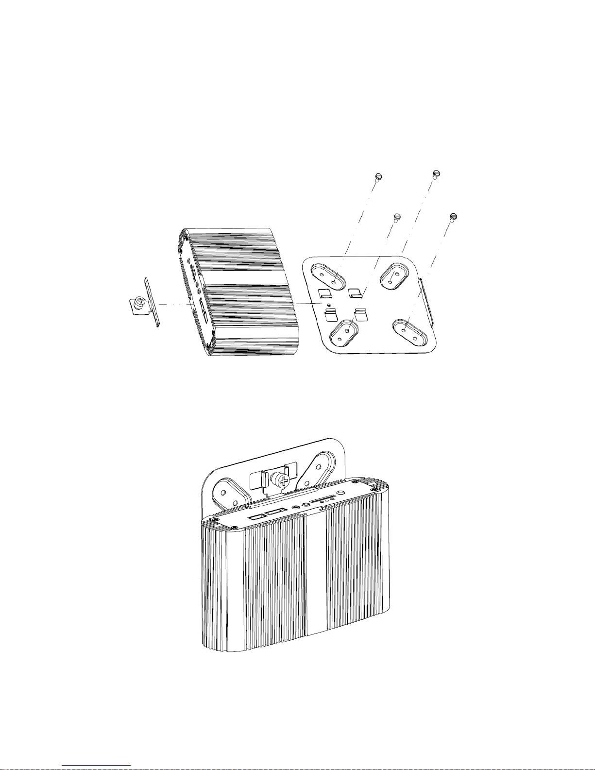
Followings are the figures of VESA mounting kit and QBox-1200.
Use the four screws to secure the kit on panel.
Sliding the screw shown in the left onto the VESA mounting kit
Figure 12 Assemble VESA Mounting Kit
Figure 13 Sliding VESA Mounting Kit onto QBox-1200
Page 26
Chapter 3
26
QBOX-1200 User’s Manual
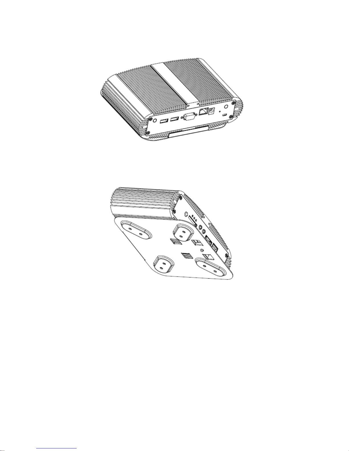
Figure 14 Rear view of QBox-1200
Figure 15 Front view of QBox-1200
Page 27
Chapter 3
27
QBOX-1200 User’s Manual
Chapter 3
AMI BIOS Setup
Overview
This chapter provides a description of the AMI BIOS. The BIOS setup menus and
available selections may vary from those of your product. For specific information on
the BIOS for your product, please contact with your dealer.
NOTE: The BIOS menus and selections for your product may vary from
those in this chapter. For the BIOS manual specific to your product, please
contact with us.
AMI's ROM BIOS provides a built-in Setup program, which allows the user to modify
the basic system configuration and hardware parameters. The modified data will
be stored in a battery-backed CMOS, so that data will be retained even when the
power is turned off. In general, the information saved in the CMOS RAM will not
need to be changed unless there is a configuration change in the system, such as a
hard drive replacement or when a device is added.
It is possible for the CMOS battery to fail, which will cause data loss in the CMOS
only. If this happens you will need to reconfigure your BIOS settings.
Page 28

Chapter 3
28
QBOX-1200 User’s Manual
Main Menu
The BIOS Setup is accessed by pressing the DEL key after the Power-On Self-Test
(POST) memory test begins and before the operating system boot begins. Once you
enter the BIOS Setup Utility, the Main Menu will appear on the screen. The Main
Menu provides System Overview information and allows you to set the System Time
and Date. Use the “<” and “>” cursor keys to navigate between menu screens.
Table 2 BIOS Main Menu
BIOS SETUP UTILITY
Main Config Boot Security Exit
System Date [Thu 07/15/2010]
System Time [10:18:15]
BIOS Information
Version: 1.22
Build date: 06/23/10
Processor ® ATOM™ CPU K510 @1.66GHz
Speed: 1666MHz
Physical Memory
Size: 1024MB
Speed: 667MHz
Use [ENTER], [TAB]
or [SHIFT-TAB] to
select a field.
Use [+] or [-] to
configure system Time.
Å Select Screen
↑↓ Select Item
+- Change Field
Tab Select Field
F1 General Help
F10 Save and Exit
ESC Exit
V02.67 (C)Copyright 1985-2009, American Megatrends, Inc.
Below table is described for Primary IDE Master, Primary IDE Slave, Secondary IDE
Master setting.
Page 29
Chapter 3
29
QBOX-1200 User’s Manual
Configuration
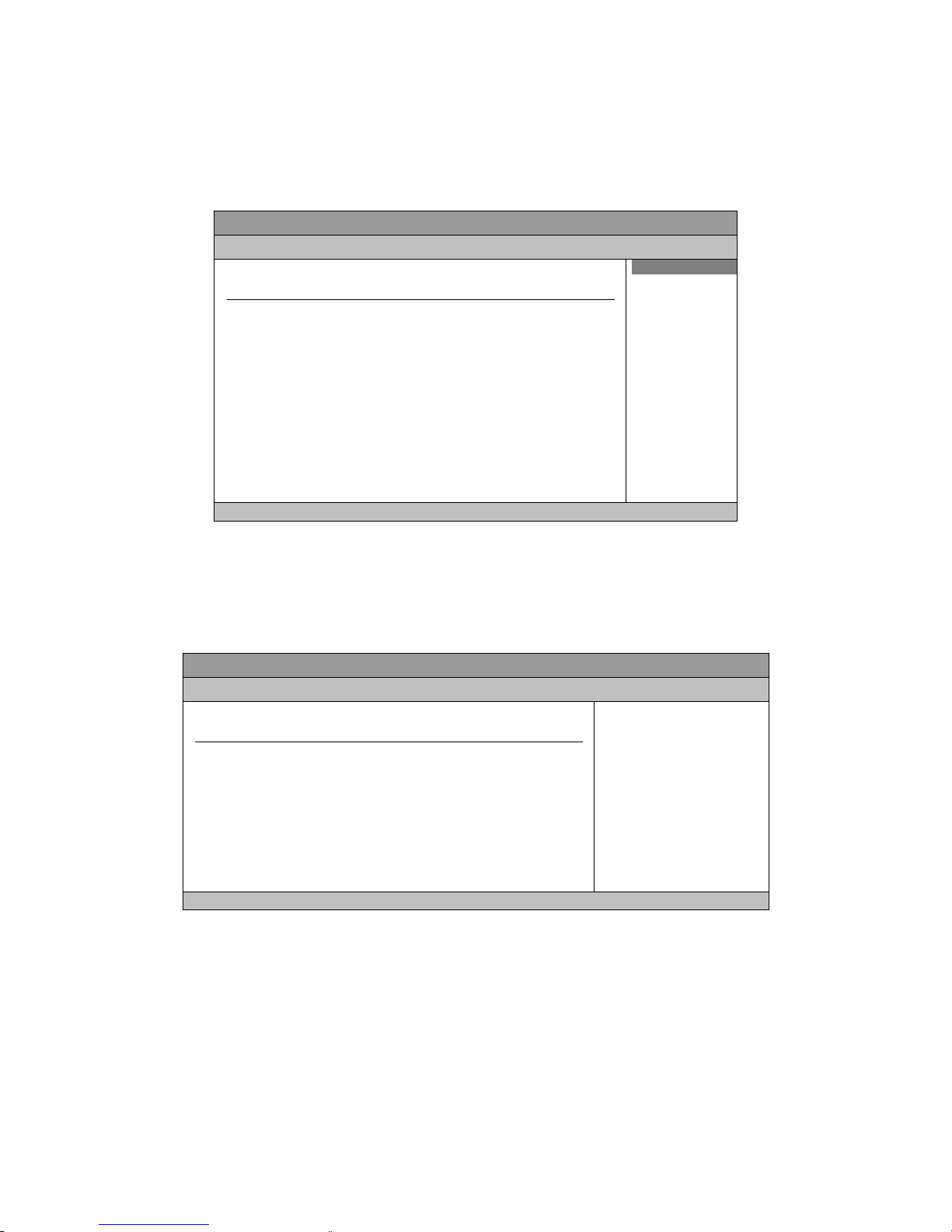
Table 3 Configuration
BIOS SETUP UTILITY
Main Config Boot Security Exit
Config Settings
Warning: Setting wrong values in below sections
may cause system to malfunction.
> OnBoard LAN PXE Boot [Disabled]
>Power
> Hardware Health Configuration
Options
Enabled
Disabled
Å Select Screen
↑↓ Select Item
+- Change Field
Tab Select Field
F1 General Help
F10 Save and Exit
ESC Exit
V02.67(C)Copyright 1985-2009, American Megatrends, Inc.
Onboard LAN PXE Boot
Options: Enabled, Disabled
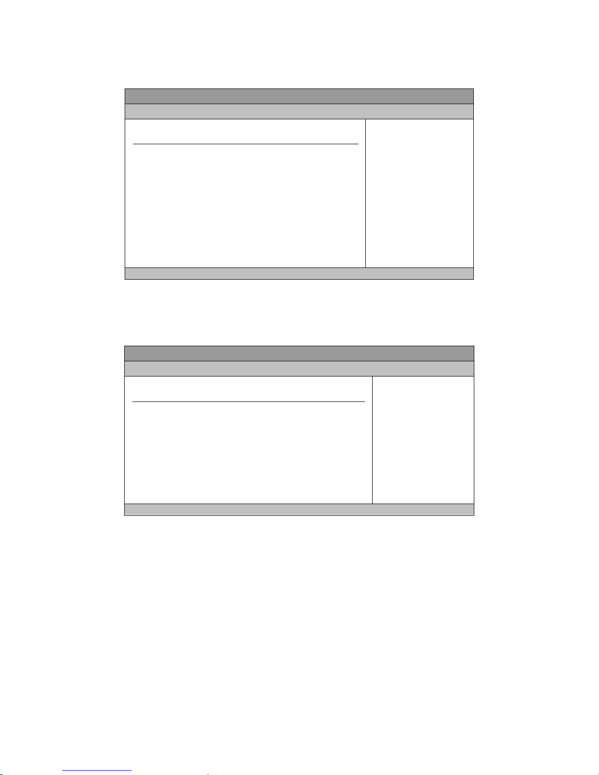
Table 4 Power Management Settings
BIOS SETUP UTILITY
Main Config Boot Chipset Power Security Exit
Power Management Settings
Suspend [S1 (POS)]
Restore on AC Power Loss [Power Off]
USB Power Status [5V]
Resume by PCI-E Device [Disabled]
Resume By RTC Alarm [Disabled]
Select the ACPI state used
For System Suspend.
Å Select Screen
↑↓ Select Item
+- Change Field
F1 General Help
F10 Save and Exit
ESC Exit
V02.67(C)Copyright 1985-2009, American Megatrends, Inc.
Suspend Mode
Options: S1 (POS), S3 (STR)
Restore on AC Power Loss
Options: Power Off, Power On, Last State
USB Power Status
Options: 5V, 5VSB
Page 30

Chapter 3
30
QBOX-1200 User’s Manual
Resume By PCI-E Device
Options: Enabled, Disabled
Resume By RTC Alarm
Options: Enabled, Disabled
Page 31
Chapter 3
31
QBOX-1200 User’s Manual
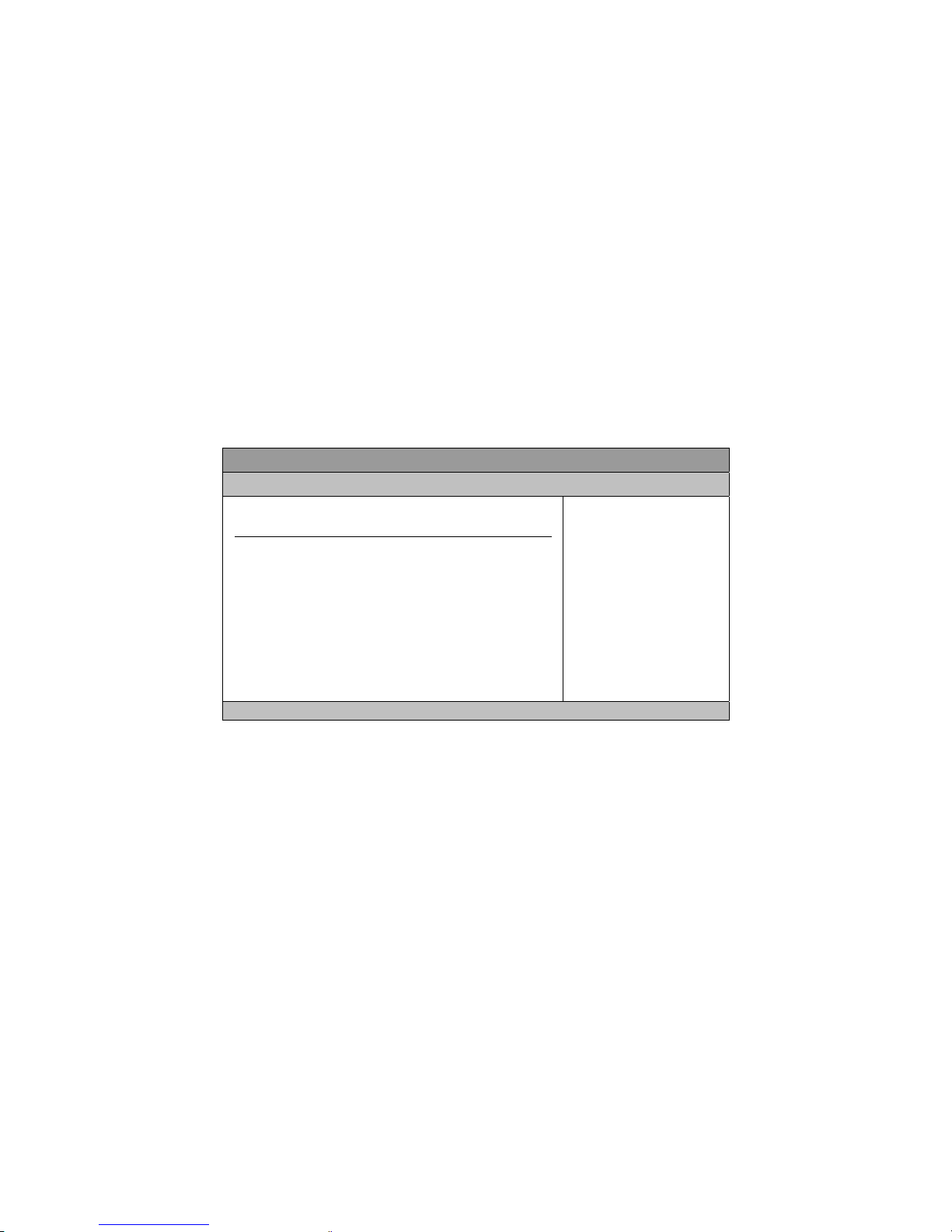
Table 5 Hardware Health Configuration
BIOS SETUP UTILITY
Main Config Boot Chipset Power Security Exit
Hardware Health Configuration
CPU Temperature :47°C/ 116°F
System Temperature :33°C/ 91°F
+VCORE :1.168 V
+3.3V :3.312 V
+5.00V :5.090V
Input :19.350V
Å Select Screen
↑↓ Select Item
+- Change Field
Tab Select Field
F1 General Help
F10 Save and Exit
ESC Exit
V02.67 (C)Copyright 1985-2009, American Megatrends, Inc.
Boot Menu
Table 6 Boot Menu
BIOS SETUP UTILITY
Main Config Boot Security Exit
Boot Settings
> Boot Device Priority
> Hard Disk Drives
> Quick Boot [Enabled]
> Full Screen Logo Display [Disabled]
> Bootup Num-Lock [On]
Specifies the Boot
Device Priority
sequence.
Å Select Screen
↑↓ Select Item
+- Change Field
F1 General Help
F10 Save and Exit
ESC Exit
V02.67 (C)Copyright 1985-2009, American Megatrends, Inc.
Boot Device Priority
The items allow you to specify the Boot Device Priority sequence.
Example: The screen may show [SATA: WDC WD1600BEV] as the 1st Boot Device in
the Screen
Hard Disk Drives
The items allow you to specify the Boot Device Priority sequence from available
Removable Drives.
Example: The screen may show [SATA: WDC WD1600BEV] as the 1st Drive in the
Screen
Page 32
Chapter 3
32
QBOX-1200 User’s Manual
Quick Boot [Enabled]
Enabling this item allows BIOS to skip some Power On Self Tests (POST) while
booting to decrease the time needed to boot the system. When set to [Disabled],
BIOS performs all the POST items.
Options: Disabled, Enabled
Full Screen Logo Display
Options: Disabled, Enabled
Bootup Num-Lock
Options: On, Off
Security Menu
Table 7 Security Menu
BIOS SETUP UTILITY
Main Config Boot Security Exit
Security Setting
Supervisor Password :Not Installed
User Password :Not Installed
Change Supervisor Password
Change User Password
Install or Change the
password.
Å Select Screen
↑↓ Select Item
+- Change Field
F1 General Help
F10 Save and Exit
ESC Exit
V02.67 (C)Copyright 1985-2009, American Megatrends, Inc.
Change Supervisor Password
Select this item to set or change the supervisor password. The Supervisor Password
item on top of the screen displays the default Not Installed. After you have set a
password, this item displays Installed.
Change User Password
Select this item to set or change the user password. The User Password item on top
of the screen displays the default Not Installed. After you have set a password, this
item displays Installed.
Page 33

Chapter 3
33
QBOX-1200 User’s Manual
Exit Menu
Table 8 Exit Menu
BIOS SETUP UTILITY
Main Config Boot Security Exit
Exit Options
Save Changes and Exit
Discard Changes and Exit
Discard Changes
Load Optimal Defaults
Exit System Setup after saving
the changes.
F10 key can be used
for this operation.
Å Select Screen
↑↓ Select Item
+- Change Field
F1 General Help
F10 Save and Exit
ESC Exit
V02.67 (C)Copyright 1985-2009, American Megatrends, Inc.
Save Changes and Exit
Exit system setup after saving the changes. Once you are finished making your
selections, choose this option from the Exit menu to ensure the values you selected
are saved to the CMOS RAM. The CMOS RAM is sustained by an onboard backup
battery and stays on even when the PC is turned off. When you select this option, a
confirmation window appears. Select [Yes] to save changes and exit.
Discard Changes and Exit
Exit system setup without saving any changes. Select this option only if you do not
want to save the changes that you made to the Setup program. If you made changes
to fields other than system date, system time, and password, the BIOS asks for a
confirmation before exiting.
Discard Changes
Discards changes done so far to any of the setup values. This option allows you to
discard the selections you made and restore the previously saved values. After
selecting this option, a confirmation appears. Select [Yes] to discard any changes and
load the previously saved values.
Load Optimal Defaults
Load Optimal Default values for all the setup values. This option allows you to load
optimal default values for each of the parameters on the Setup menus, which will
provide the best performance settings for your system. The F9 key can be used for
this operation.
Page 34

Chapter 4
34
QBOX-1200 User’s Manual
Chapter 4
Driver Installation
If your QBOX-1200 does not come with an operating system pre-installed, you will
need to install an operating system and the necessary drivers to operate it. After you
have finished assembling your system and connected the appropriate power source,
power it up using the power supply and install the desired operating system.
For other operating systems, please contact with your dealer.
 Loading...