


Technical Support Line: (952) 985-5675 Email: Info@QA1.net
21730 Hanover Ave.
Lakeville, MN 55044
INSTALL INSTRUCTIONS
QA1 P/N MU1RCA, MU2RCA, MU3RCA ’79-’04 MUSTANG RACE SERIES CONTROL ARMS
QA1 P/N MU1ESA, MU2ESA, MU3ESA ’79-’04 MUSTANG STREET SERIES CONTROL ARMS
READ ALL INSTRUCTIONS CAREFULLY AND THOROUGHLY PRIOR TO STARTING INSTALLATION. PRODUCTS THAT HAVE BEEN INSTALLED ARE NOT ELIGIBLE FOR
RETURN. USE THE PROPER JACKING LOCATIONS. DEATH OR SERIOUS INJURY CAN RESULT IF INSTRUCTIONS ARE NOT CORRECTLY FOLLOWED. A GOOD CHASSIS
MANUAL, AVAILABLE AT YOUR LOCAL PARTS STORE, MAY ALSO AID IN YOUR INSTALLATION.
• DISCLAIMER / WARRANTY •
QA1 WARRANTS THAT THE PRODUCTS WILL BE FREE FROM DEFECTS IN MATERIAL AND WORKMANSHIP FOR ONE YEAR FROM DATE OF SALE TO THE ORIGINAL
PURCHASER. QA1 MAKES NO OTHER WARRANTY OF ANY KIND, EXPRESS OR IMPLIED. QA1 SHALL HAVE NO OBLIGATION UNDER THE FOREGOING WARRANTY
WHERE THE DEFECT IS THE RESULT OF IMPROPER OR ABNORMAL USE, YOUR NEGLIGENCE, VEHICLE ACCIDENT, IMPROPER OR INCORRECT INSTALLATION OR
MAINTENANCE, NOR WHEN THE PRODUCT HAS BEEN REPAIRED OR ALTERED IN ANY WAY. QA1’S LIABILITY IN THE CASE OF DEFECTIVE PRODUCTS SUBJECT
TO THE FOREGOING WARRANTY SHALL BE LIMITED TO THE REPAIR OR REPLACEMENT, AT QA1’S OPTION, OF THE DEFECTIVE PRODUCTS.
THE USER UNDERSTANDS AND RECOGNIZES THAT RACING PARTS, SPECIALIZED STREET ROD EQUIPMENT, AND ALL PARTS AND SERVICES SOLD BY QA1 ARE
EXPOSED TO MANY AND VARIED CONDITIONS DUE TO THE MANNER IN WHICH THEY ARE INSTALLED AND USED. QA1 SHALL BEAR NO LIABILITY FOR ANY
LOSS, DAMAGE OR INJURY, EITHER TO A PERSON OR TO PROPERTY, RESULTING FROM THE INSTALLATION, DIRECT OR INDIRECT USE OF ANY QA1 PRODUCTS
OR INABILITY BY THE BUYER TO DETERMINE PROPER USE OR APPLICATION OF QA1 PRODUCTS. WITH THE EXCEPTION OF THE LIMITED LIABILITY WARRANTY
SET FORTH ABOVE, QA1 SHALL NOT BE LIABLE FOR ANY CLAIMS, DEMANDS, INJURIES, DAMAGES, ACTIONS, OR CAUSES OF ACTION WHATSOEVER TO BUYER
ARISING OUT OF OR CONNECTED WITH THE USE OF ANY QA1 PRODUCTS. MOTORSPORTS ARE DANGEROUS; AS SUCH, NO WARRANTY OR REPRESENTATION
IS MADE AS TO THE PRODUCT’S ABILITY TO PROTECT THE USER FROM INJURY OR DEATH. THE USER ASSUMES THAT RISK.
TOOLS AND SUPPLIES REQUIRED
• Floor Jack • Jack Stands • Tire Chocks • Coil-over Struts
• Tape Measure • Drill & 3/8” bit •Torque Wrench • Common Hand Tools
REMOVAL:
1. Before starting the installation of your QA1 control arms read the instructions carefully and thoroughly. A good service
manual, available at your local parts store may aid in the installation. Check to make sure all of the parts and tools
needed to complete this installation are on hand.
2. Jack up the car so that jack stands can be placed under the frame. Let the jack down so that the frame sets securely on
the stands.
3. Remove the wheels and then unbolt the brake calipers. Secure the brake calipers out of the way of the control arms
(do not let the caliper hang from the brake line. This can cause damage to the brake line). For vehicles equipped with
ABS, refer to your Ford manual for safe removal.
4. Remove the sway bar end links from the vehicle. (Inspect for bushing wear and replace as needed)
5. Use the floor jack to support one of the A-arm assemblies. Jack the A-arm up just enough to take the load off of the
strut and spindle. Use of a spring compressor to contain the spring energy is highly recommended. (Fox body cars will
require the removal of the rotor backing plate before continuing.) Remove the cotter pin from the castle nut on the
ball joint. Loosen the castle nut enough to separate the ball joint. Once the ball joint has been loosened from the
spindle the castle nut should be removed. Slowly, CAREFULLY, let the A-arm assembly down until the spring is free and
can be removed.
6. Repeat this procedure for the opposite side.
www.QA1.net
9919-161 Rev 04112018
1

CONTROL ARM PART NUMBER
END OF ROD END TO
CENTER OF BALL JOINT
MU1RCA
13.687”
MU2RCA
14.875”
MU3RCA
14.687”
Figure 1
Figure 2
7. Loosen and remove the two bolts and nuts holding each A-arm into the K-member.
8. Inspect the bolts for any defects or wear. Replace hardware if needed. (QA1 p/n 52395)
NOTE: Installation of control arms to QA1 K member will slightly vary as the front bolt will thread into the K member.
PRE-INSTALLATION INSTRUCTIONS: *RACE SERIES CONTROL ARMS*
1. Identify the left and right side A-arms. The tube with the sway bar
attachment will point toward the front of the car.
2. Install 3/4”-16 jam nuts onto 3/4”-16 threaded rod ends and
thread into control arm.
3. Place control arm pivot points against a flat surface and measure
to the center of the ball joint to the following length.
(See Figure 2)
INSTALLATION INSTRUCTIONS: *RACE SERIES CONTROL ARMS*
1. Install the control arm into the K-member on each side of the car using the included spacers. Identify the different
sized spacers and install as shown in Figure 1.
Note: The age and condition of your stock K-member may require resizing of QA1 Race Series control arm spacers for correct fitment.
2. Tighten control arm hardware to 130 lb.-ft.
2
9919-161 Rev 04112018
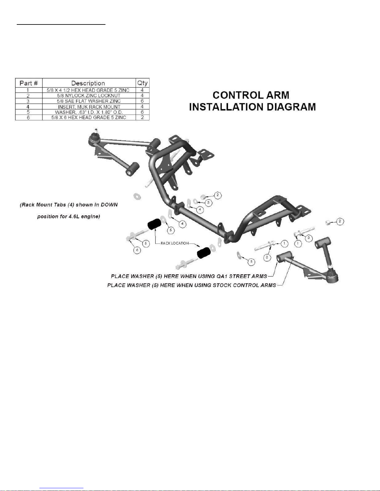
INSTALLATION INSTRUCTIONS: *STREET SERIES CONTROL ARMS*
1. Identify the left and right side control arms. The tube with the sway bar attachment will point toward the front of
the car.
2. Install the control arm into the K-member on each side of the car. If installing control arms into QA1 k-member, see
Figure 3 or refer to your k-member instructions for correct washer placement.
Figure 3
3. Hand tighten control arm hardware, keeping in mind the final torque should be done with car at ride height as to
not bind the bushings.
4. Grease both ball joints using general automotive grease or synthetic grease.
NOTE: IF THE VEHICLE WAS NOT PREVIOUSLY USING COIL-OVER STRUTS, REFER TO THE NEW COIL-OVER INSTRUCTIONS
BEFORE CONTINUING.
5. Reinstall the brake rotor, caliper, and backing plates.
6. Reinstall the ABS sensor.
7. Reinstall both front wheels.
8. Set ride height by adjusting the spring seat adjuster on the body of the strut.
9. Lock the spring seat adjuster once desired ride height is achieved.
10. Double check all bolts and make sure that they are torqued to manufacture specifications.
11. Torque control arms to 130 lb.-ft. with car at ride height.
12. Bring the vehicle to a reputable shop for a quality frontend alignment to factory specs.
3
9919-161 Rev 04112018
Maintenance of QA1 Ultimate Ball Joints
Grease using high quality NLGI #2 GC-LB Lithium based grease and check preload on a regular basis. Check and
set ball joint preload at least annually or every 3,000 miles, whichever comes first. NOTE: Preload on the ball
stud can be set with the ball joint attached to the control arm if the spring is unloaded and the ball joint taper is
free from the spindle.
1. Using the QA1 spanner socket from Ball Joint Tool Kit (p/n 1891-106) loosen the lock nut by turning counter
clockwise.
2. Using the QA1 hex key, torque the torque nut to 25-30 in. lbs. and then back off 90°.
3. Using the QA1 hex key, a ½’’ open-ended wrench or socket, and the QA1 spanner wrench, tighten the lock
nut while holding the torque nut, locking them together to 25 ft. lbs.
4. Re-check the lash on the ball stud and adjust as needed. The ball stud should not have any axial lash.
9919-161 Rev 04112018
4
 Loading...