

Page 1
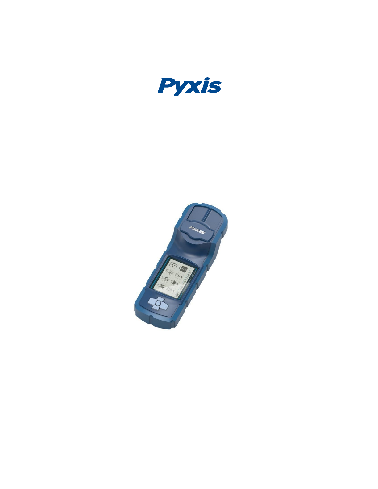
SP-910 Portable Water Analyzer
Operation Manual
Rev.C
Pyxis Lab, Inc 2017
All Rights Reserved
Page 2

Page 3

1
1 Contents
General Description ............................................................................................... 6
1.1 Pyxis Major Features .............................................................................................. 7
1.2 Unpackaging the Instrument ................................................................................. 7
1.3 Standard Accessories ............................................................................................. 8
1.4 Optional Accessories .............................................................................................. 8
1.5 Sample Vial Compartment ..................................................................................... 8
1.6 Light Shield Cover ................................................................................................... 8
2 Start The SP-910.......................................................................................... 10
2.1 Battery Installation ............................................................................................... 10
2.2 Description of the Navigational Control Pad ....................................................... 10
2.3 Turning on the SP-910 .......................................................................................... 11
2.4 Main Page ............................................................................................................. 11
2.5 Turning Off The SP-910 ........................................................................................ 11
2.6 The SP-910 Auto Power Off.................................................................................. 12
2.7 Auto LCD Power Saving ........................................................................................ 12
3 PTSA Measurement ..................................................................................... 13
3.1 PTSA Measurement .............................................................................................. 13
3.2 PTSA calibration ................................................................................................... 14
4 Fluorescein Measurement ............................................................................ 15
4.1 Fluorescein Measurement ................................................................................... 15
4.2 Fluorescein calibration (Firmware version before v1.0r295)............................... 15
4.3 Fluorescein calibration (Firmware version v1.0r295 and after) .......................... 16
5 Colorimetric Measurement ........................................................................... 18
5.1 Supported Methods ............................................................................................. 18
5.2 Select a Method ................................................................................................... 20
5.3 Single Timing Step Method .................................................................................. 20
5.4 Single-Vial Procedure ........................................................................................... 21
Page 4

2
5.5 Two-Vial Methods ................................................................................................ 22
5.6 Multiple Timing Steps Method ............................................................................. 22
5.7 Advanced Methods .............................................................................................. 23
5.8 Method Setup and Calibration ............................................................................. 25
6 Turbidity Measurement ............................................................................................ 27
6.1 Operation ............................................................................................................. 27
6.2 Turbidity Calibration ............................................................................................. 27
7 Absorbance Measurement ...................................................................................... 30
8 Update SP-910 firmware via Bluetooth Interface ................................................. 31
8.1 Download and Install the Latest Nebula Software ............................................... 31
8.2 Turn on SP-910 ..................................................................................................... 32
8.3 Connect Nebula to the SP-910 ............................................................................. 32
9 Upgrade the ChemTreat Product List ........................................................... 33
10 Calibrate a ST-500 with SP-910 ................................................................... 34
11 Maintenance ................................................................................................. 37
12 Troubleshooting ............................................................................................ 38
13 Appendix A. .................................................................................................. 39
Page 5

3
Figures
Figure 1 Insert the Sample Vial.............................................................................................. 7
Figure 2 Open and Close the Light Shield Cover ................................................................... 9
Figure 3 Replace Batteries ................................................................................................... 10
Figure 4 Main Menu ............................................................................................................ 11
Figure 5 PTSA Measurement ............................................................................................... 13
Figure 6 Product Selection .................................................................................................. 13
Figure 7 PTSA Calibration .................................................................................................... 14
Figure 8 Fluorescein Measurement ..................................................................................... 15
Figure 9 Fluorescein Calibration .......................................................................................... 16
Figure 10 Low Range Fluorescein Calibration ..................................................................... 17
Figure 11 Middle Range Fluorescein Calibration................................................................. 17
Figure 12 High Range Fluorescein Calibration..................................................................... 17
Figure 13 Method Selection ................................................................................................ 20
Figure 14 Single Timer Method ........................................................................................... 21
Figure 15 Concentration as a Function of Time .................................................................. 21
Figure 16 Multiple Timer Method ....................................................................................... 23
Figure 17 Method Form Selection ....................................................................................... 25
Figure 18 Method Unit Selection ........................................................................................ 26
Figure 19 Slope Calibration ................................................................................................. 26
Figure 20 Turbidity Calibration-1 ........................................................................................ 28
Figure 21 Low Range Calibration ......................................................................................... 28
Figure 22 High Range Calibration ........................................................................................ 29
Figure 23 Absorbance Measurement .................................................................................. 30
Figure 24 Nebula Setup ....................................................................................................... 31
Figure 25 Bluetooth Adapter Driver Setup .......................................................................... 31
Figure 26 Bootloader Menu ................................................................................................ 32
Figure 27 Bluetooth Ready .................................................................................................. 32
Figure 28 Scan Inline Device ................................................................................................ 34
Figure 28 Pair Inline Device ................................................................................................. 34
Figure 29 Read Inline Device ............................................................................................... 35
Figure 30 SP-910 Measure Sample Water ........................................................................... 35
Figure 31 Calibration Success .............................................................................................. 35
Figure 32 Inline Device Diagnosis Data ............................................................................... 36
Figure 33 Cleanliness Check ................................................................................................ 36
Figure 34 Probe is Fouled .................................................................................................... 36
Page 6

4
Tables
Table 1 Feature Groups on Main Menu ............................................................... 11
Table 2 List of Supported Colorimetric Methods ................................................. 18
Table 3 Wavelength of each channel ................................................................... 30
Table 4 Contact Information ................................................................................ 38
Page 7

5
Trademarks and Patents
Hach ® is a registered trademark of the Hach Company, Loveland, CO USA
Confidentiality
The information contained in this manual may be confidential and proprietary and is the property of
Pyxis Lab. Information disclosed herein shall not be used to manufacture, construct, or otherwise
reproduce the goods disclosed herein. The information disclosed herein shall not be disclosed to
others or made public in any manner without the express written consent of Pyxis Lab.
Standard Limited Warranty
Pyxis Lab warrants its products for defects in materials and workmanship. Pyxis Lab will, at its
option, repair or replace instrument components that prove to be defective with new or
remanufactured components (i.e., equivalent to new). The warranty set forth is exclusive and no
other warranty, whether written or oral, is expressed or implied.
Warranty Term
The Pyxis warranty term is thirteen (13) months ex-works. In no event shall the standard limited
warranty coverage extend beyond thirteen (13) months from original shipment date.
Warranty Service
Damaged or dysfunctional instruments may be returned to Pyxis for repair or replacement. In some
instances, replacement instruments may be available for short duration loan or lease.
Pyxis warrants that any labor services provided shall conform to the reasonable standards of
technical competency and performance effective at the time of delivery. All service interventions are
to be reviewed and authorized as correct and complete at the completion of the service by a
customer representative, or designate. Pyxis warrants these services for 30 days after the
authorization and will correct any qualifying deficiency in labor provided that the labor service
deficiency is exactly related to the originating event. No other remedy, other than the provision of
labor services, may be applicable.
Repair components (parts and materials), but not consumables, provided in the course of a repair, or
purchased individually, are warranted for 90 days ex-works for materials and workmanship. In no
event will the incorporation of a warranted repair component into an instrument extend the whole
instrument’s warranty beyond its original term.
Shipping
A Repair Authorization Number (RA) must be obtained from the Technical Support (service@pyxislab.com) before any product can be returned to the factory. Pyxis will pay freight charges to ship
replacement or repaired products to the customer. The customer shall pay freight charges for
returning products to Pyxis. Any product returned to the factory without an RA number will be
returned to the customer.
Page 8

6
General Description
Specification1
• Colorimeter Wavelength: 365/420/455/525/560/570/630 nm
• Turbidity Excitation: White/Infrared LED/90 degree scattering
• Fluorescence Excitation Wavelength: 365/460 nm LED
• Fluorescence Emission Wavelength: 410/520 nm
• Wavelength Accuracy: ±1 nm
• Absorbance Reproducibility: 0.005 au (0 - 1.0 au) (3 sigma)
• Absorbance Linearity Range: 0 - 1.0 au
• PTSA Reproducibility: 1 ppb PTSA (3 sigma)
• PTSA Detection Limit: 1 ppb
• PTSA Range: 0 - 300 ppb
• Fluorescein Reproducibility: 0.2 ppb or 2% of the value
• Fluorescein Detection Limit: 0.1 ppb
• Fluorescein Range: 600 ppb
• Turbidity Reproducibility: 1 NTU (3 sigma)
• Turbidity Detection Limit: 1 NTU
• Turbidity Range: 1 - 200 NTU
• Battery: 4 AA alkaline
• Typical Battery Life: 3 months
• Display: Graphical LCD 192x128 pixels,
visible under direct sunlight
• Instrument Dimension: L 265mm W 88mm H 62mm
• Instrument Weight: 600 g without batteries
• Storage Temperature Range: 0 - 140°F (-18 - 60°C )
• Operation Temperature Range: 40 - 120 °F (4 - 49°C )
• Humidity: 85% at 106 °F (41 °C )
• Environmental: IP67, dustproof and waterproof
Note:
1. Specifications are subject to change without notice for continuous development.
2. The fluorescein range in earlier versions of the SP-910 may be only up to 20 ppb.
To extend the upper limit to 600 ppb, please contact Pyxis customer support at
[email protected].
Page 9
7
1.1 Pyxis Major Features
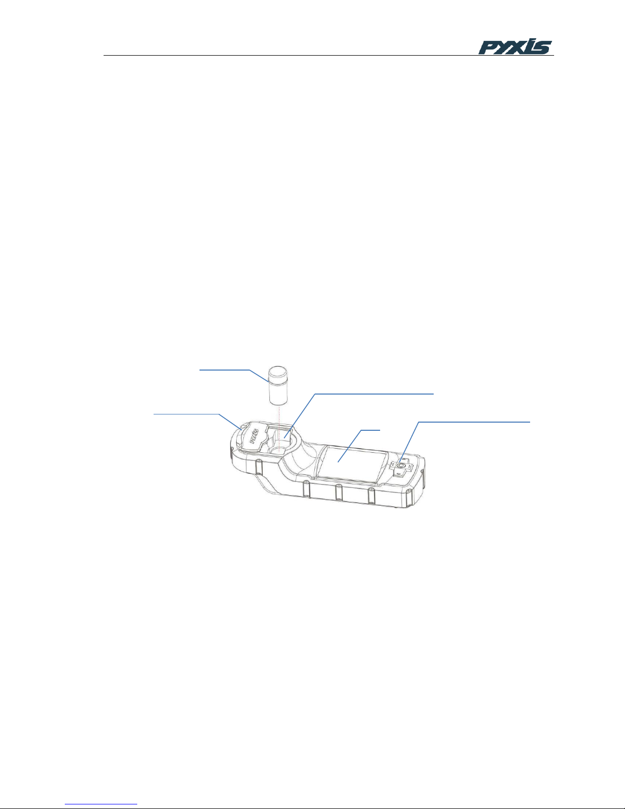
The SP-910 analyzer shown in Figure 1 is a combination of photometer and
fluorometer. It provides colorimetric measurements at 7 LED wavelengths, fluorometric
measurement of fluorescent tracer PTSA and fluorescein, and nephelometric turbidity
measurement using white LED and infrared LED as excitation sources. The SP-910 is
pre-calibrated for colorimetric measurements of analyses common in industrial water
treatment and other water testing applications in the laboratory or in the field, such as
measuring chlorine, phosphate, iron, and copper. Main features include:
The SP-910 is pre-calibrated for measuring PTSA (pyrenetetrasulfonic acid) in the
range of 0 to 300 ppb. The fluorescence PTSA measurement is automatically
compensated for sample color and turbidity interference.
The SP-910 is pre-calibrated for measuring fluorescein in the range of 0 to 600
ppb.
The SP-910 is pre-calibrated for measuring turbidity in the range of 0 to 200 NTU.
Automatically select the primary wavelength according to the method selected and
switches to the secondary wavelength to extend the primary measurement range.
Figure 1 Insert the Sample Vial
Display a concentration-time profile curve in a colorimetric measurement. The user
can terminate the timing process and take a reading if the displayed concentration
reaches a plateau before completing the predefined time period.
The user can update the calibration parameter of any pre-calibrated colorimetric
method by testing a standard solution first and then following a setup procedure to
update the calibration parameters.
1.2 Unpackaging the Instrument
Remove the instrument and accessories from the shipping container and inspect each
item for any damage that may have occurred during shipping. Verify that all items
Navigational Control Pad
LCD
Sample Vial Compartment
Light Shield Cover
Sample Vial
Page 10

8
listed on the packing slip are included. If any items are missing or damaged, please
contact Pyxis Customer Service at [email protected].
1.3 Standard Accessories
• Sample Vials - two 10 ml, round, 0.78 inch (20 mm) pathlength, glass vials,
which can be used for all measurements including turbidity and fluorescence
measurements
• 4 AA alkaline batteries
• Instrument Manual, also available from www.pyxis-lab.com
1.4 Optional Accessories
• 25 ml sample vial
• 100 ppb PTSA standard in a 500 ml brown plastic bottle
• 50, 250,and 500 ppb fluorescein standards in a 500 ml brown plastic bottle
1.5 Sample Vial Compartment
The sample vial compartment is shown in Figure 1, along with a 10-ml sample vial.
When the sample vial is inserted into the sample vial compartment, the triangular mark
on the sample vial should be aligned approximately with the 6 o’clock position of the
sample vial compartment or any position consistently.
The sample vial compartment should be kept clean. A small amount foreign material
could significantly affect turbidity and fluorescence measurement results. Use a soft
cloth or lint free paper tissue to clean sample vial compartment periodically. Remove
debris, scale, and deposit promptly.
1.6 Light Shield Cover
The light shield cover is shown in Figure 2. The light shield cover can be conveniently
slid between the open and closed positions. The light shield cover is held firmly at the
rest positions by permanent magnets.
The light shield cover should be in the closed position during storage, transportation,
and measurements, especially during the turbidity and fluorescence measurements.
When turned on, The SP-910 carries out self-diagnosis including checking the
performance of a variety of optical devices. The light shield door shall be at the closed
position to shield interference from ambient light during self-diagnosis.
Care should be taken to avoid water or debris being trapped in the track of the light
shield door.
Page 11

9
Figure 2 Open and Close the Light Shield Cover
Warning
Magnetic sensitive devices, including but not limited to, credit cards, watches, hard
disks, should be keep at a distance of at least 2 inches from the Light Shield Door to
avoid possible damage and/or loss of information recorded.
Page 12
10
2 Start The SP-910
2.1 Battery Installation
The SP-910 is powered by four AA-size alkaline batteries. Do not use rechargeable
nickel cadmium (NiCad) batteries or any AA-size lithium batteries. A set of batteries
typically lasts for three months. When the batteries capacity is low, The SP-910 will
prompt a LOW BATTERY warning. Replace all four batteries to resume operation of
the SP-910 after the battery warning.
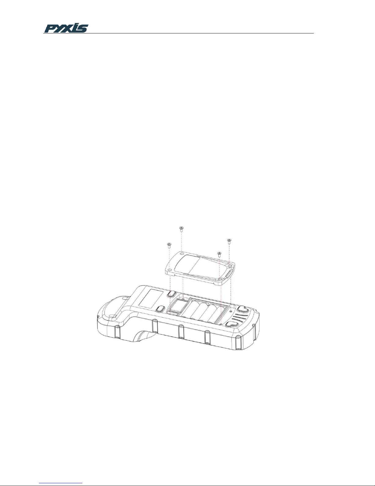
The SP-910 battery compartment, shown in Figure 3, is on the back side of the
instrument. Insert a small pad underneath the screen area to make the back surface
level when the instrument is turned upside down. Install batteries as followings:
1. Remove the battery compartment cover by loosening four screws.
2. Insert four batteries into the battery holder as shown in Figure 3. Make sure the
positive battery polarity marker (+) is aligned with the positive marker (+) on the
battery holder.
3. Replace the battery compartment cover, making sure that the sealing O-ring is
lying flat on the battery holder and tighten the four screws.
Figure 3 Replace Batteries
2.2 Description of the Navigational Control Pad
The SP-910 navigational control pad consists of five keys as shown in Figure 1. The
left, right, up, and down keys are navigational keys that are used to select an icon, a
button, or other items in various pages. The center key is the OK key. Press the OK
key on a selected item to launch the action associated with the selected item. The OK
Page 13
11
key is also used to accept the current selection, like the return key in a computer
keyboard.
2.3 Turning on the SP-910
After new batteries installation, the SP-910 will not be automatically turned on. To turn
on SP-910, press the OK key, and release the OK key when the LCD is lit.
You can navigate the main page menu and launch an operation by pressing on an
icon. If battery voltage is too low for the instrument to work properly, the SP-910 will
show a low battery warning message when it is being turned on. If this happens,
replace all four batteries.
2.4 Main Page
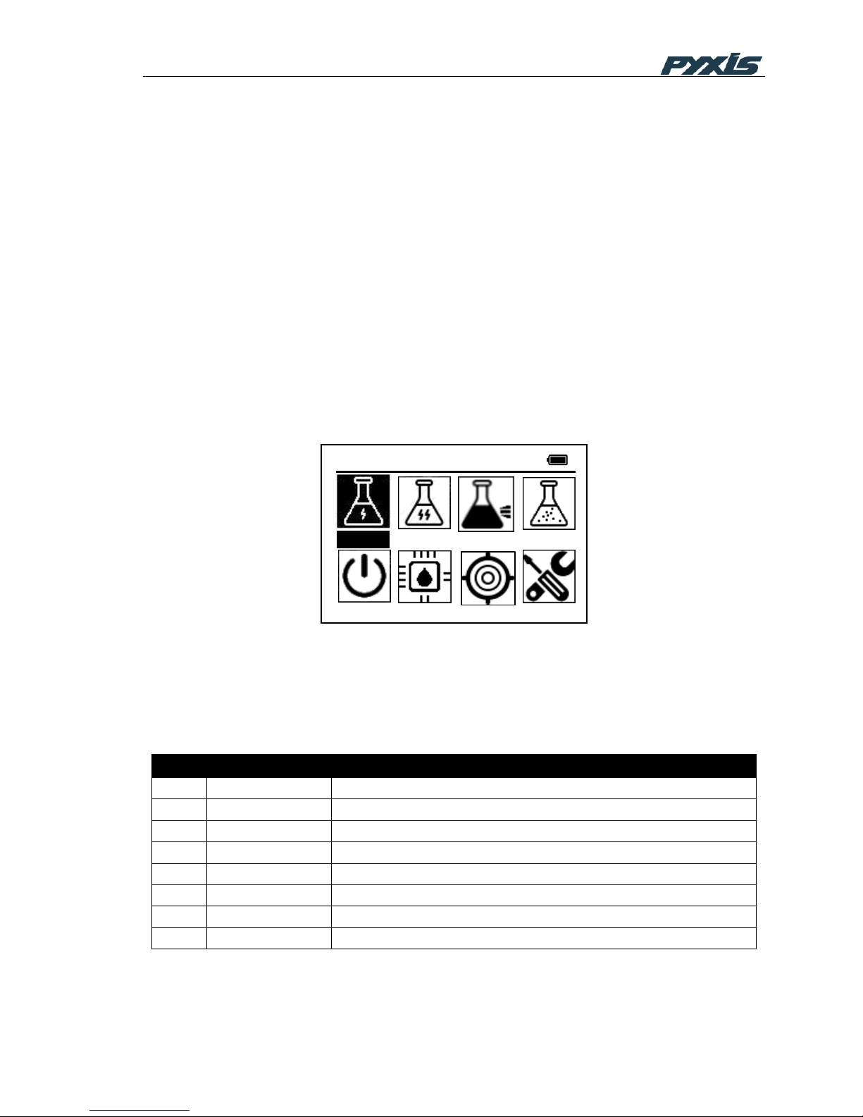
The SP-910 provides intuitive icon driven user operations. On the main page, eight
major feature groups are illustrated as below:
Figure 4 Main Menu
A brief description of each feature group is given in Table 1. Detailed operation instructions
can be found in the following chapters.
Table 1 Feature Groups on Main Menu
No.
Title
Description
1
M-P
PTSA measurement
2
M-F
Fluorescein measurement
3
COLOR
Colorimetric measurement methods
4
TURB
Turbidity measurement
5
Power
Turn off SP-910
6
ABSB
Absorbance measurement
7
CAL
Calibration routines
8
SYS
System setup and information
2.5 Turning Off The SP-910
2016/07/19 08:00
Power
M-F
TURB
ABSB
SYS
M-P
CAL
COLOR
Page 14

12
Turn the SP-910 off by navigating to Power icon and press the OK key. Alternatively,
you can turn off the SP-910 by pressing OK key for 5 seconds in any menu.
2.6 The SP-910 Auto Power Off
The SP-910 automatically turns itself off with no-key activity for a given period, except
for during a measurement. The auto power-off time can be set in SYS->System Set.
Pressing OK key will wake up the instrument, and the SP-910 will return to the original
page if it has any measurement data.
2.7 Auto LCD Power Saving
During a colorimetric method measurement, The SP-910 automatically turns LCD
backlight off with no-key activity. The auto LCD power-off time can be set in
SYS->System Set. Pressing any key will turn on the LCD backlight. Under normal
ambient lighting condition, icons and other contents shown on the LCD screen are
readable without backlight being on.
Page 15
13
3 PTSA Measurement
3.1 PTSA Measurement
1. Fill the 10 ml sample vial with water sample and tightly cap the sample vial.
2. Place the sample vial into the sample vial compartment and slide the light shield
cover to the closed position.
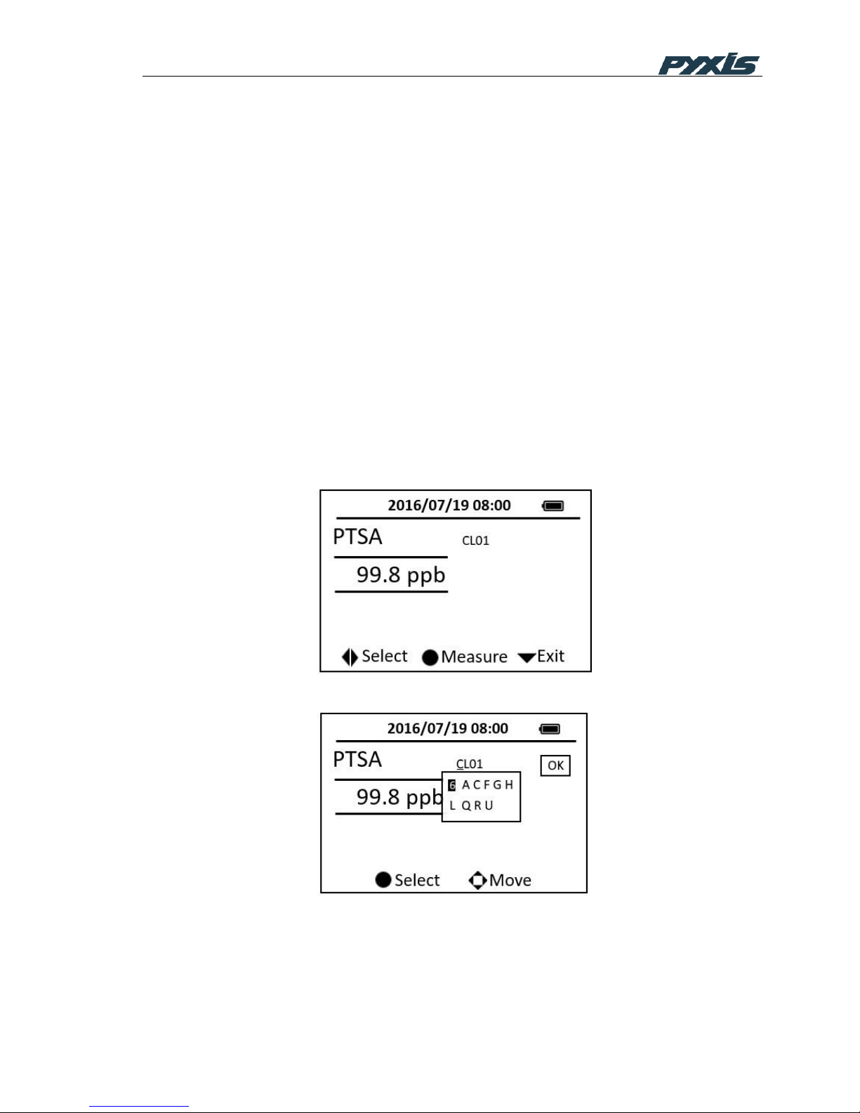
3. Press the M-P icon on the main page. The SP-910 will start to measure the PTSA
concentration.
4. The SP-910 will display the ppm concentration of the last selected ChemTreat
cooling product.
5. Press the OK key on the selected character, a dropdown list containing possible
selectable characters will be shown below the product name. Use the down, right
or left key to locate a character and press the OK key to select (Figure 6). Repeat
this action until all characters in the target product name are being selected. Use
the “OK” button on the screen to accept the product name. The displayed ppm
value will be updated according to the calibration parameters of the selected
product.
Figure 5 PTSA Measurement
Figure 6 Product Selection
If CL01 is selected, the displayed value is ppb PTSA concentration without PTSA-toProduct conversion.
Page 16
14
The SP-910 with earlier versions of firmware may show mistakenly the PTSA value
in ppm after selecting CL01. Regardless the software version and the unit shown on
the right, the value after selecting CL01 is always ppb PTSA.
On-screen key instructions in the earlier version of firmware are text based and
may be different from those shown in figure 5.
During the fluorescence measurement to determine the PTSA concentration, the SP910 checks the sample turbidity. If the sample turbidity value detected is greater than
40 NTU, The SP-910 will display a warning. For best results, the sample should be
filtered if turbidity exceeds 40 NTU.
Sample color causes a lower PTSA concentration to be measured. The SP-910
automatically compensates for sample color. If the sample color is too intense, The
SP-910 will display a warning.
For best results, ensure that the sample vial is clean. Wipe off water on the outside
wall of the sample vial using a lint-free tissue paper. Fill the sample vial to the 10 ml
mark. If the sample contains air bubbles, tap the sample vial gently to remove the
bubbles before placing the sample vial to the sample vial compartment.
3.2 PTSA calibration
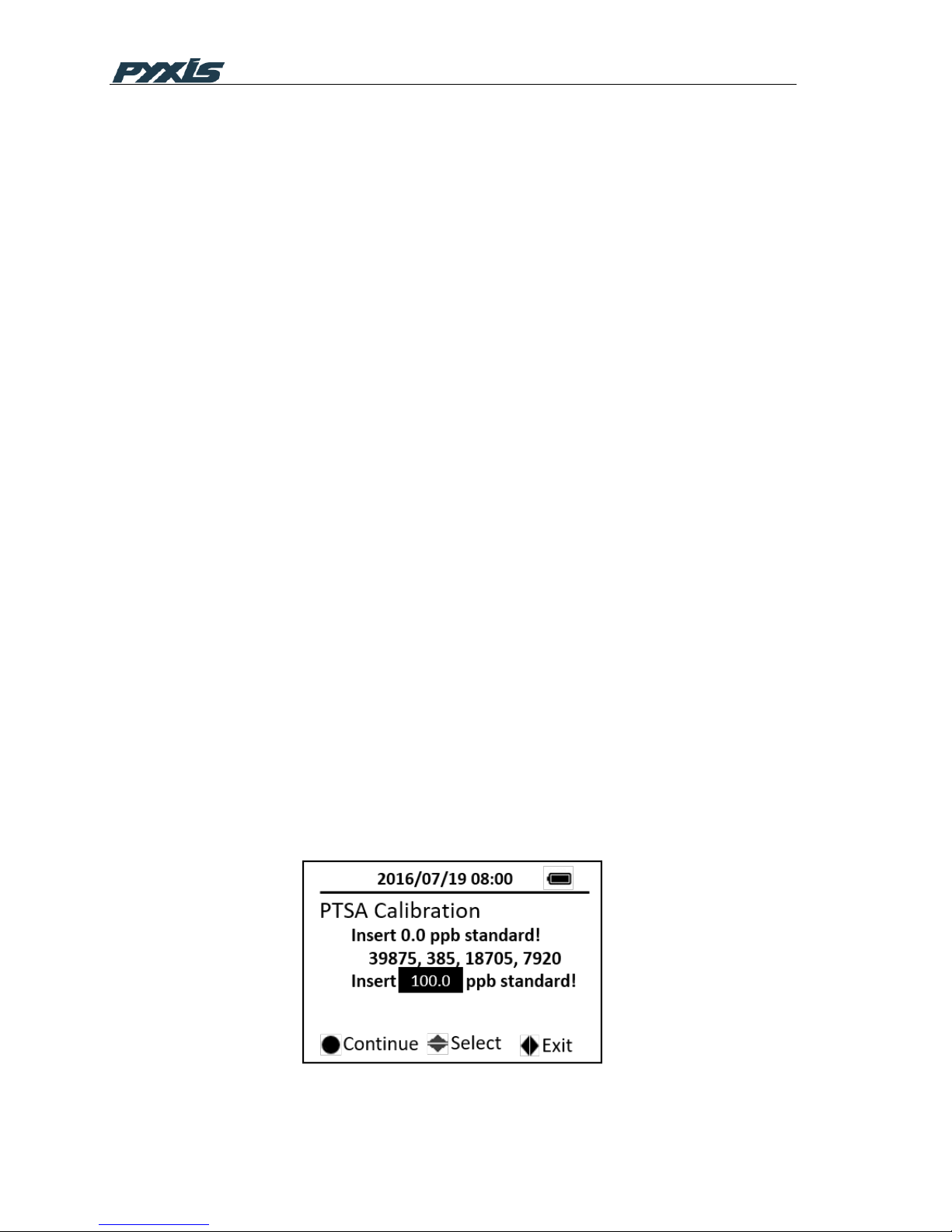
Deionized water (DI) as the blank calibration solution and the 100 ppb PTSA calibration
standard solution are needed.
1. Press the CAL on the main page, then choose the M-P and press the OK key to
launch the PTSA calibration page.
2. Follow the message prompts, fill the sample vial with DI blank and place the
sample vial into the sample vial compartment and press the OK key.
3. Follow the message prompts, use the upper and down key to switch between 100
ppb and 200 ppb standard
4. Fill the sample vial with the 100 ppb or 200 ppb standard and place the sample vial
into the sample vial compartment and press the OK key to start calibration
Figure 7 PTSA Calibration
Page 17
15
If calibration fails, the followings should be checked:
• The DI blank is being contaminated.
• The 100 ppb PTSA standard solution is decayed or being contaminated.
• The light shield cover is not in the closed position.
• The sample vial compartment is blocked with debris, water, or other materials.
The 100 ppb standard solution shall be stored in a brown or black opaque bottle.
Exposing the PTSA standard to light will cause the standard losing the PTSA
concentration. Many substances, such as quaternary amine cause a negative
interference. Many other substances such as laundry detergents that contain optical
brightener will cause a significant positive interference.
4 Fluorescein Measurement
4.1 Fluorescein Measurement
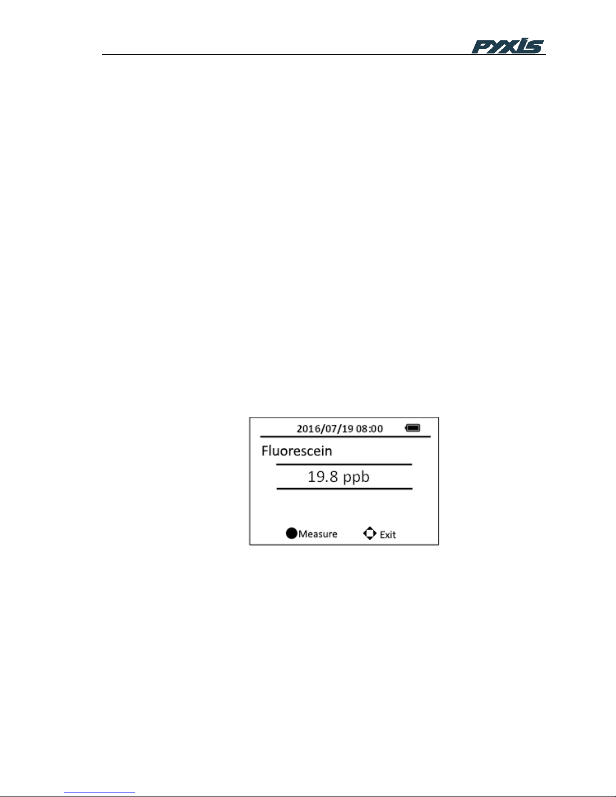
1. Fill the 10 ml sample vial with the test solution and tightly cap the sample vial.
2. Place the sample vial into the sample vial compartment and slide the light shield
cover to the closed position.
3. Press the M-F on the main page, then press the OK button, the SP-910 will start to
measure the fluorescein concentration in the sample.
4. The SP-910 will display the fluorescein concentration in ppb.
Figure 8 Fluorescein Measurement
For best results, ensure that the sample vial is clean. Wipe off water on the outside
wall of the sample vial using a lint-free tissue paper. Fill the sample vial to the 10 ml
mark. If the sample contains air bubbles, tap the sample vial gently to remove the
bubbles before placing the sample vial to the sample vial compartment.
4.2 Fluorescein calibration (Firmware version before v1.0r295)
Deionized water (DI) as the blank calibration solution and the 20 ppb fluorescein
calibration standard solution are needed.
Page 18
16
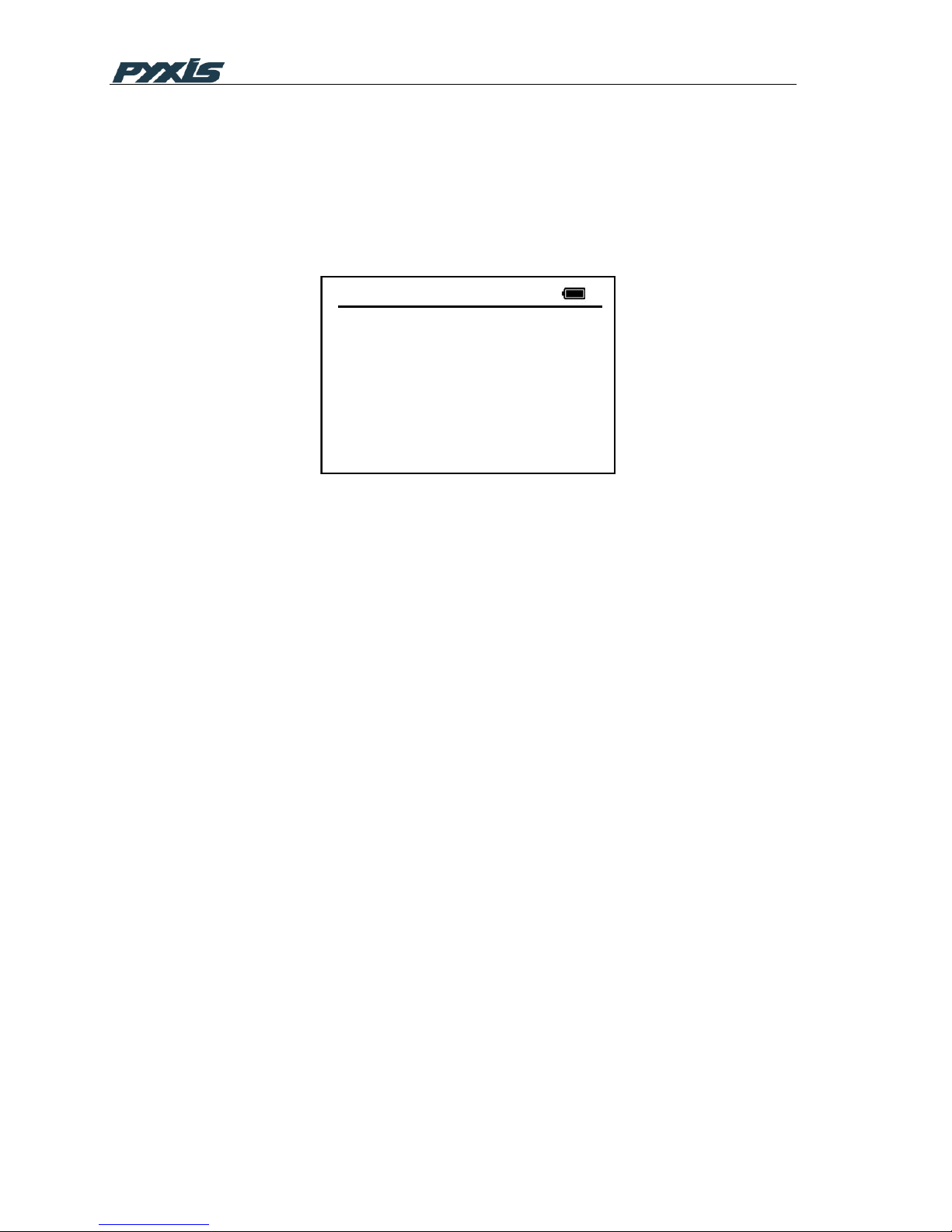
1. Press the CAL on the main page, then choose Fluorescein and press the OK key
to launch the fluorescein calibration page.
2. Follow the message prompts, insert the DI blank into the sample vial compartment
and press the OK key.
3. Follow the message prompts, and insert the 20 ppb standard into the sample vial
compartment and press the OK key.
4. Press any key to return to the main page.
Figure 9 Fluorescein Calibration
If calibration fails, the followings should be checked:
• The DI blank is being contaminated.
• The 20 ppb fluorescein standard solution is decayed or being contaminated.
• The light shield cover is not in the closing position.
• The sample vial compartment is blocked with debris, water, or other materials.
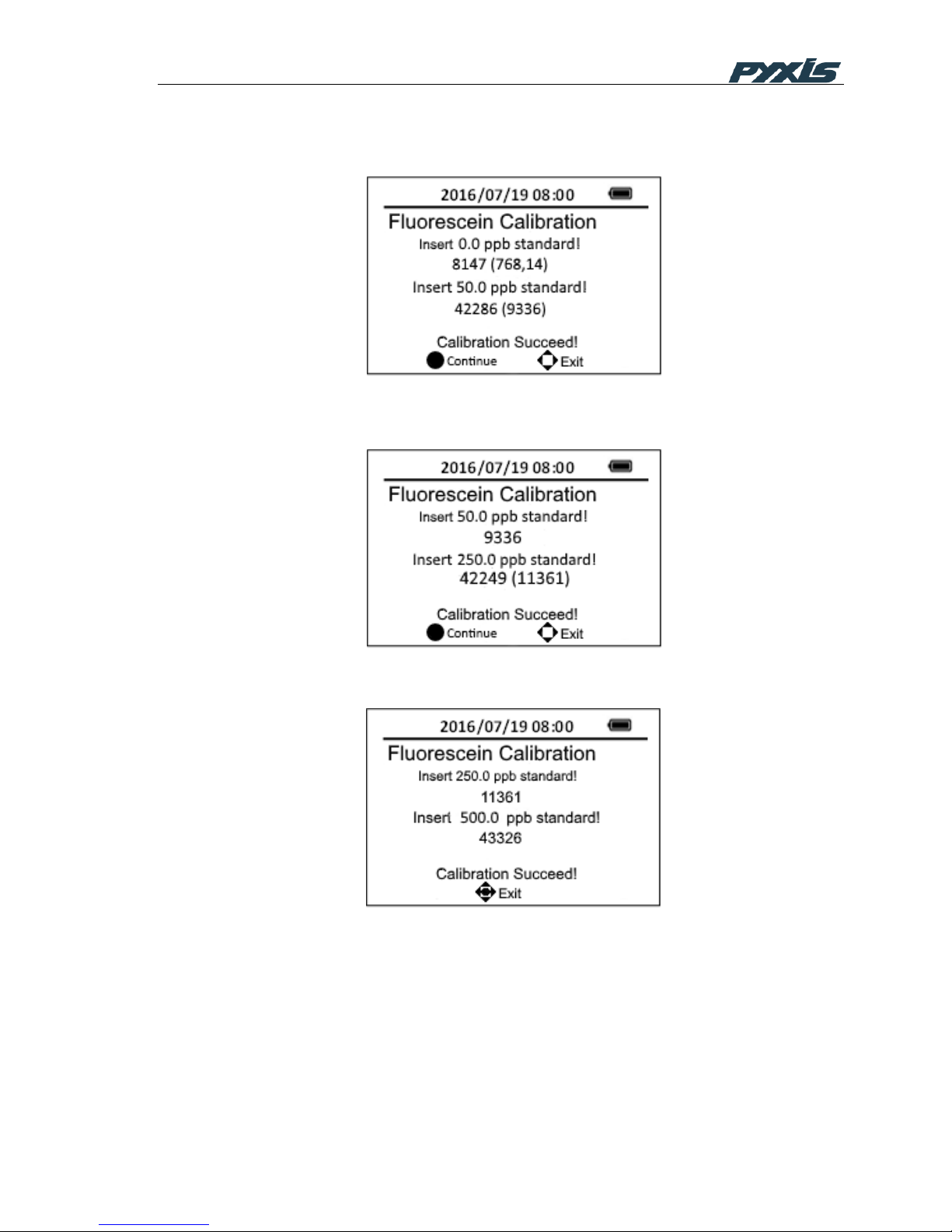
4.3 Fluorescein calibration (Firmware version v1.0r295 and after)
Deionized water (DI) as the blank calibration solution, the 50 ppb fluorescein, the 250
ppb fluorescein and the 500 fluorescein calibration standard solutions are needed.
1. Press the CAL on the main page, then choose Fluorescein and press the OK key
to launch the fluorescein calibration page.
2. Follow the message prompts, insert the DI blank into the sample vial compartment
and press the OK key.
3. Insert the 50 ppb standard into the sample vial compartment and press the OK key
to complete the low range calibration.
4. Press the OK key to proceed with middle range calibration or press any other keys
to return to main page.
5. Insert the 250 ppb standard into the sample vial compartment and press the OK
key to complete the middle range calibration.
6. Press the OK key to start proceed with high range calibration or press any other
keys to return to main page.
7. Insert the 500 ppb standard into the sample vial compartment and press the OK
key to complete the high range calibration.
2016/07/19 08:00
M-F Calibration
Insert 0.0 ppb standard!
7730
Insert 20.0 ppb standard!
Click OK key to continue!
Click up and down key to change!
Page 19
17
The middle range and high range calibrations from steps 4 to 8 are optional if only low
range fluorescein measurement is intended.
Figure 10 Low Range Fluorescein Calibration
Figure 11 Middle Range Fluorescein Calibration
Figure 12 High Range Fluorescein Calibration
The standard solutions shall be stored in a brown or black opaque bottle. Exposing the
fluorescein standard to light will cause the standard losing the fluorescein
concentration. Many substances, such as quaternary amine cause a negative
interference. Many other substances such laundry detergents that contain optical
brightener will cause a significant positive interference.
Page 20

18
5 Colorimetric Measurement
5.1 Supported Methods
A wide range of colorimetric methods is supported by the SP-910 analyzer and the
number of them keeps increasing with continuous development of Pyxis. See
corresponding Hach® methods in Appendix A.
Table 2 List of Supported Colorimetric Methods
Abbreviated
Method
Name
Method Name
Description
Range
CL-F
F-Chlorine
Free chlorine, DPD method
2.2 ppm
CL-T
T-Chlorine
Total chlorine, DPD method
2.2 ppm
CL2H
CL2High
High range, DPD method
6.0ppm
CuBi
Cu_Bicinch
Bicinchoninate, EPA approved
for reporting wastewater
analysis
5.0 ppm
DEHA
DEHA
Method for N,Ndiethylhydroxylamine and other
oxygen scavengers
0.5 ppm
Ca
Ca
Calmagite method for calcium
4.00 ppm as
CaCO3
Mg
Mg
Calmagite method for
magnesium
4.00 ppm as
CaCO3
FePh
Fe_phenanth
Total iron using 1,10phenanthroline, USEPA
approved for reporting
wasterwater analysis
3.00 ppm
FeZi
FeZine
FerroZine method
1.300 ppm
FeTp
FeTptz
Total iron using TPTZ
1.80 ppm
MoHR
Mo_HighRange
High range molybdate
40.0 ppm
MoLR
Mo_LowRange
Low range molybdate using
ternary complex method
3.0 ppm
NO2H
NO2H
High range nitrite, ferrous
sulfate method
150 ppm as
NO2
NO2L
NO2L
Low range nitrite, diazotization
method, USEPA approved for
reporting wastewater and
drinking water analysis
0.350 ppm
as NO2
PMoV
OPO4-MoV
Reactive phosphate using
molybdovanadate method
30.0 ppm as
PO4
OPO4
OPO4
Reactive phosphate using
ascorbic acid molybdenum blue
method, USEPA accepted for
wastewater analysis
2.5 ppm as
PO4
Page 21

19
Abbreviated
Method
Name
Method Name
Description
Range
OrgP
Phosphonate
UV digestion and ascorbic acid
reduction molybdenum blue
method
7.1 ppm as
PBTC
PAmi
OPO4-Amino
Reactive phosphate, amino
acid reduction method
30.0 ppm
ClO2
ClO2-DPD
DPD method, USEPA accepted
for reporting drinking water
analysis
5.00 ppm
ClO2D
ClO2Direct
Direct method for chlorine
dioxide
35.0 ppm
SiHR
SiHR
High range silica
75.0 ppm as
SiO2
SiLR
SiLR
Low range silica
1.60 ppm as
SiO2
AZOL
Azole
UV digestion for tolyltriazole
and benzotriazole
16.0 ppm
SO4
SO4
Barium sulfate turbdimetric
method
70.0 ppm
POLY
Polymer
Turbidimetric method for
anionic polymeric dispersant
13.0 ppm as
PAA
FeMo
FeMo
Total iron method for water
containing molybdate
1.80 ppm
Cr6
Cr6
1,5-Diphenylcarbohydrazide
method for chromium
hexavalent,USEPA accepted
for wastewater analyses
0.6ppm
CrT
CrTot
Alkaline hypobromite Oxidation
method for chromium total
0.6ppm
NH3S
NH3Sal
Salicylate method for
nitrogen,ammonia
0.5ppm
NH2C
NH2CL
Indophenol method for
chloramine mono
3.0ppm
N2H4
N2H4
p-Dimethylaminobenzaldehyde
method for hydrazine
0.5ppm
MnL
MnLow
Low range manganese
0.7ppm
MnH
MnHigh
High range manganese
20.0ppm
BLCH
Bleach
Direct Method measuring
sodium hypochlorite
concentration
AL
Alumi
Aluminon method for aluminum
0.8ppm
F
Floride
SPADNS method for fluoride
2.0ppm
CuL
CuPorp
Porphyrin Method for copper
0.2ppm
Zn
Zinc
Zincon method for zinc,USEPA
approved for wastewater
analysis
3.0ppm
Page 22
20
Abbreviated
Method
Name
Method Name
Description
Range
S2-
Sulfide
Methylene blue method for
sulfide,USEPA accepted for
reporting wastewater analysis
0.7ppm
CN
Cyanide
Pyridine-Pyrazalone method for
cyanide
0.2ppm
NO3M
NO3M
Middle range nitrate
5ppm as N
NO3H
NO3H
High range nitrate
30ppm as N
Ni
Ni
PAN method for nickel
1ppm
CYAN
CYAN
Turbidimetric method for
cyanuric acid
55ppm
pH
pH
Phenol red method for pH
8.5
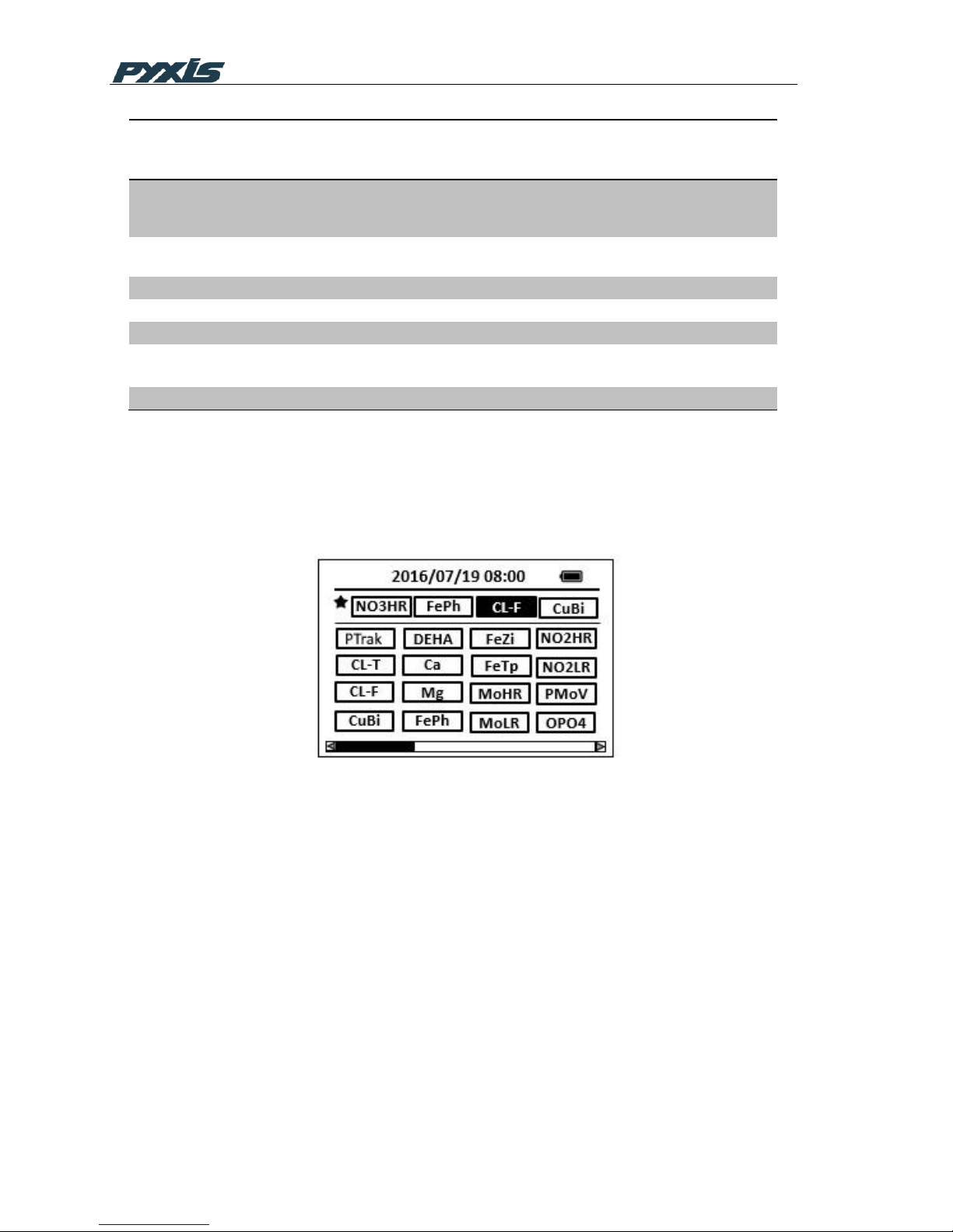
5.2 Select a Method
Move the icon focus to the method icon Mthd using the navigational (left, right, up, or
down) keys. Press OK on the icon to launch the first method selection page. The
methods shown on the top row of the page are the most frequently selected methods.
Figure 13 Method Selection
The followings are the operations associated with this page:
1. Use the navigational keys and the OK key to select and launch a method.
2. Long press the OK key to return to the main page. Press the arrow icon at the
lower right corner of the page to display the second method selection page if the
device is loaded with more than 23 methods.
Note: Methods shown in the method selection pages include Hach© equivalent
methods and Pyxis specific advanced methods. The table in Appendix A provides a
brief description of Pyxis method names and their corresponding Hach® program
number. Hach® reagents for 10 ml sample can be used for the test.
5.3 Single Timing Step Method
Page 23
21
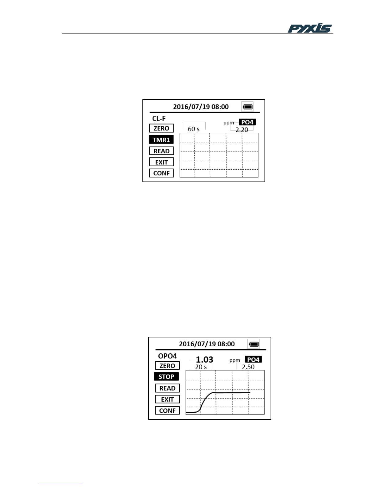
Most of colorimetric methods have only one timing step. As an example, in the DPD
free chlorine method, it takes three minutes for the DPD powder reagent to completely
react with chlorine in the water sample. The DPD free chlorine method has a single
three-minute timing step. Figure 10 shows the main page of a method with a single
timing step.
Figure 14 Single Timer Method
5.4 Single-Vial Procedure
1. Place the sample vial filled with the water sample in the SP-910 sample vial
compartment and press the ZERO button. The SP-910 will display the page shown
in Figure 14.
2. Take the sample vial out and add the reagent to the sample vial.
3. Place the sample vial back into the sample vial compartment and press the timer
button TMR1. The SP-910 will start to monitor the reaction between the reagent
and the species you want to measure in the water sample. The concentration is
shown in the chart as a function of time (Figure15).
4. When the timer reaches the preset time and the reaction is complete, the value of
concentration will be shown on the top of the page.
5. The rate of the reaction is often faster than the standard pre-set time, which will
become apparent from the concentration-time plot. You can press the STOP
button to stop the timer and terminate the timing step. The last read concentration
value will be displayed on the top of the page after you terminate the timing step.
Figure 15 Concentration as a Function of Time
Page 24

22
5.5 Two-Vial Methods
Some colorimetric methods require using two vials. The water sample is added to two
identical vials. One vial is being used to zero the colorimeter, referred as to the
prepared blank. A reagent is added to the other vial, referred as to the prepared
sample. The absorbance value is determined from the prepared sample.
If the method requires two or more reagents, the prepared blank could be the resulting
solution after one or more reagents have been added to the sample.
The following procedure is typical for two-vial methods:
1. Place the prepared blank into the SP-910 sample vial compartment and press the
ZERO button to zero the instrument.
2. Place the prepared sample into the SP-910 sample vial compartment and press
the TMR1 button to start the method timer.
3. When the timing step is completed, the measured concentration will be displayed
on the top of the page. The timing step could be terminated earlier by pressing
STOP button.
4. Optionally, The SP-910 can be re-zeroed using the prepared blank after the timing
step is completed or terminated. The blank reading will be subtracted from the
measured concentration value, and the displayed concentration value on the topright corner will be updated. This step is optional. It is only necessary if the
prepared blank changes its color during the timing period.
5. Optionally, the prepared sample vial can be put back and read again by pressing
the READ button if the blank is re-zeroed after the timing step is completed or
terminated. A new concentration value based on the last absorbance value
measured will be calculated and displayed.
5.6 Multiple Timing Steps Method
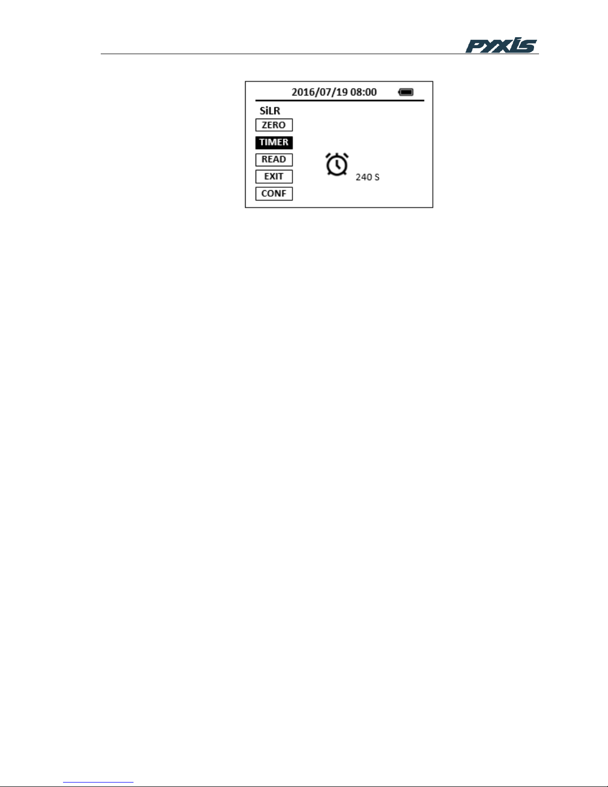
Some colorimetric methods have two or three timing steps. The SP-910 shows a
count-down timer for the timing steps before the last timing step (Figure 16). During
these timing steps, one or more reagents are added to the sample, or operations such
as shaking the vial to mix the reagent and the sample are being performed. These
methods usually use one vial for the prepared blank and the other for the prepared
sample.
Page 25
23
Figure 16 Multiple Timer Method
In order to show the concentration-time curve as shown in Figure 15 during the last
timing step, The SP-910 must be zeroed using the prepared blank before the last
timing step. Thus, the last timer button will not be selectable until the SP-910 has been
zeroed using the prepared blank. Multi-timing step Hach® methods require zeroing the
colorimeter using the prepared blank after the last timing step is completed. The SP910can optionally be re-zeroed using the prepared blank after the last timing step. The
blank value measured will be subtracted from the concentration value measured at the
end of the last timing step. Optionally, the READ button could be pressed to read the
prepare sample again.
The following procedure is typical for methods having two-timing steps:
1. Press the TMR1 button to start the first timer. Complete the necessary
operations to prepare the blank and the sample.
2. Place the prepared blank into the SP-910 sample vial compartment and
press the ZERO button.
3. Place the prepared sample into the SP-910 sample vial compartment and
press the TMR2 button to start the second timer. The SP-910 will display the
measured concentration as a function of time as shown in Figure 15.
4. When the timing step is completed, the measured concentration will be
displayed on the top right of the screen. The timing step could be terminated
earlier by pressing STOP button.
5. Optionally, The SP-910 can be re-zeroed using the prepared blank after the
timing step is completed or terminated. The blank reading will be subtracted
from the measured concentration value, and the displayed concentration
value on the top-right corner will be updated. This step is optional. It is only
necessary if the prepared blank changes its color during the timing period.
5.7 Advanced Methods
The SP-910 provides 7 LED wavelengths and can measure absorbance values at
multiple LED wavelengths. Consequently, The SP-910 can provide many predefined
Page 26

24
advanced methods that traditionally require complex and often expensive lab testing
procedures.
Low range, direct reading chlorine dioxide, 0 to 35.0 ppm
The maximum absorption bank of aqueous chlorine dioxide is around 360nm. The
SP-910 has a 365nm UV LED and can be used to directly measure chlorine dioxide.
It offers a much lower detection limit (0.2 ppm) than direct methods available from
other portable colorimeters having only light sources in the visible range.
Select ClO2D in the method selection page and carry out the following steps to
measure chlorine dioxide:
1. Place a vial filled with deionized water into the vial compartment and press the
ZERO button to zero the SP-910.
2. Discard the deionized water and fill the same vial with the sample. Place the
vial into the vial compartment and press READ button to read. The measured
chlorine dioxide concentration will be displayed in the top of the method page.
Direct Reading Bleach Percent Method, 0 to 15%
The SP-910 has a 365nm UV LED and other deep blue LEDs that can be used to
directly measure bleach concentration in the range of 0 to 15%. No reagent is
required for the method and the displayed result is the sodium hypochlorite
concentration in percentage.
Select BLCH in the method selection page and carry out the following steps to
measure chlorine dioxide:
1. Place a vial filled with deionized water into the vial compartment and press the
ZERO button to zero the SP-910.
2. Discard the deionized water and fill the same vial with the bleach sample.
Place the vial into the vial compartment and press READ button to read. The
measured bleach concentration will be displayed in the top of the method
page.
ChemTreat PolyTrak Method
1. Press Icon COLOR to launch the colorimetric method page. Select PTrk and
press the OK key to start the PolyTrk method.
2. Fill a sample vial to the 10 ml mark.
3. Add 0.5 ml Polymer Conditioning Reagent #1 to the sample and tightly cap the
sample vial. Swirl the sample vial to mix.
4. Place the sample vial to the sample compartment. Press the ZERO button.
5. Move the sample vial out. Add 0.5 ml Polymer Reactant Reagent #2 first, and
then add one level of scoop of Reagent #3 (Polymer Powder Precipitant).
6. Press TMR1 to start the 3 minute timer.
Page 27
25
7. Gently shake the sample vial for 30 seconds.
8. Place the sample vial back to the sample compartment. Product concentration
will be updated and plotted on the screen every 3 seconds.
When the 3 minute timer is reached, the final concentration will be shown on
the screen. The timer can be terminated earlier by pressing the STOP button.
The last read concentration value will be displayed after the timing step is
terminated.
A ChemTreat product name can be selected before starting the method. Click
on the right key to highlight the first digit after CL in the product name. Press
the OK key on the selected digit. A dropdown list containing possible
selectable digits will be displayed below the product name (figure xx). Use the
down, right or left keys to locate a digit and press OK to select. Use the OK
button to accept the product name.
The product name can be selected after the method is completed. The
displayed ppm value will be updated according to the calibration parameters of
the selected product name.
Select CL02 to show the raw absorbance value.
5.8 Method Setup and Calibration
Press the SETUP button in the method result page to launch the method setup and
calibration page.
5.8.1 Set up the method parameters
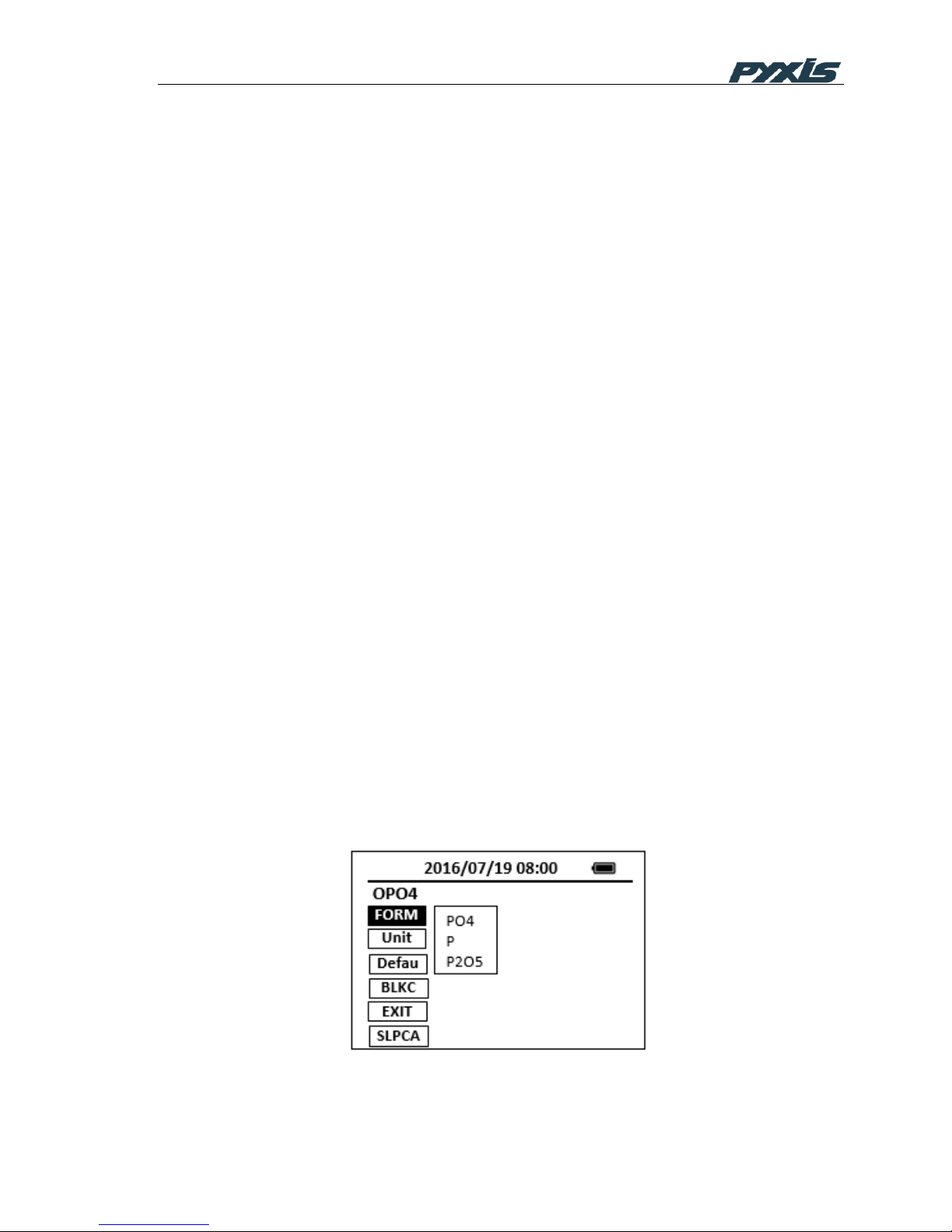
Press the FORM button to select a concentration form from the list of forms that
are available for this specific method (Figure 17).
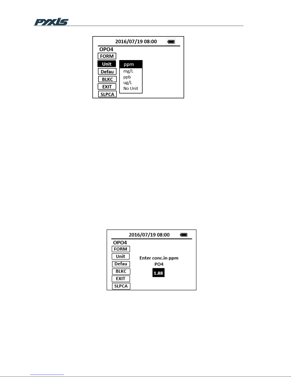
Press the UNIT button to select a concentration unit among the list of ppm, mg/L,
ppb, ug/L and No Unit (Figure 18).
Figure 17 Method Form Selection
Page 28
26
Figure 18 Method Unit Selection
5.8.2 Slope Calibration
If the method has been calibrated prior to shipping, there is no need to
calibrate unless a calibration check indicates that the method needs a
calibration. The following steps are used to calibration a method:
1. Use a calibration standard of known concentration. Follow the steps
required by the method and note the value reported by the SP-910.
2. If the measured value differs from the known standard value, Press the
CONFG button to launch the method configuration page.
3. Press the slope calibration button SlpCal. A numeric keyboard will be
displayed.
4. Enter the concentration value and press the OK key on the enter key in
the numeric keyboard to return to the configuration page.
5. Press the EXIT button. Press the OK key to accept the calibration or other
key to cancel the calibration.
Figure 19 Slope Calibration
For best results, the concentration of the standard solution should be less than
the maximum concentration for the method (table 2) and greater than the half
of the maximum concentration. For example, to calibrate total chlorine, the
Page 29

27
chlorine concentration in the standard solution should be between 1.1 and 2.2
ppm.
The corresponding calibration parameters will be updated and saved in the
memory as the working calibration parameter set. Note that this set of
calibration parameters are not the same as the default set. You can use
Default button to copy the default calibration parameters to the working set.
5.8.3 Reagent Blank Calibration
Some methods have a non-zero intercept value in the calibration equation. For
these methods, a proper non-zero intercept value is pre-loaded in SP-910
prior to shipping. The following steps are used to carry out a reagent blank
calibration:
1. Follow the normal steps to carry out a measurement on a deionized water
sample.
2. Press the CONFG button to launch the method configuration page.
3. Press the reagent blank calibration button BLKC
4. Press the OK key to save when exiting from the configuration page or
press other keys to cancel.
5.8.4 Resume to Default Calibration Parameters
Pressing the Default button will copy the default calibration intercept and
slope to the working intercept and slope, respectively. If the default calibration
parameters were created prior to shipping, this button action is to restore the
working calibration parameters to the original factory loaded calibration
parameters.
6 Turbidity Measurement
6.1 Operation
Follow the following steps to measure turbidity:
1. Fill the 10 ml sample vial to above the 10 ml mark.
2. Insert the sample vial to the sample vial compartment.
3. Slide the light shield cover to the closed position.
4. Press the Turb on the main page, then press the OK key, The SP-910 will
start to measure the turbidity in the sample.
6.2 Turbidity Calibration
1. Fill the 10 ml sample vial to above 10 ml mark with the deionized water.
2. Insert the sample vial to the sample vial compartment.
Page 30
28
3. Slide the light shield cover to the closed position.
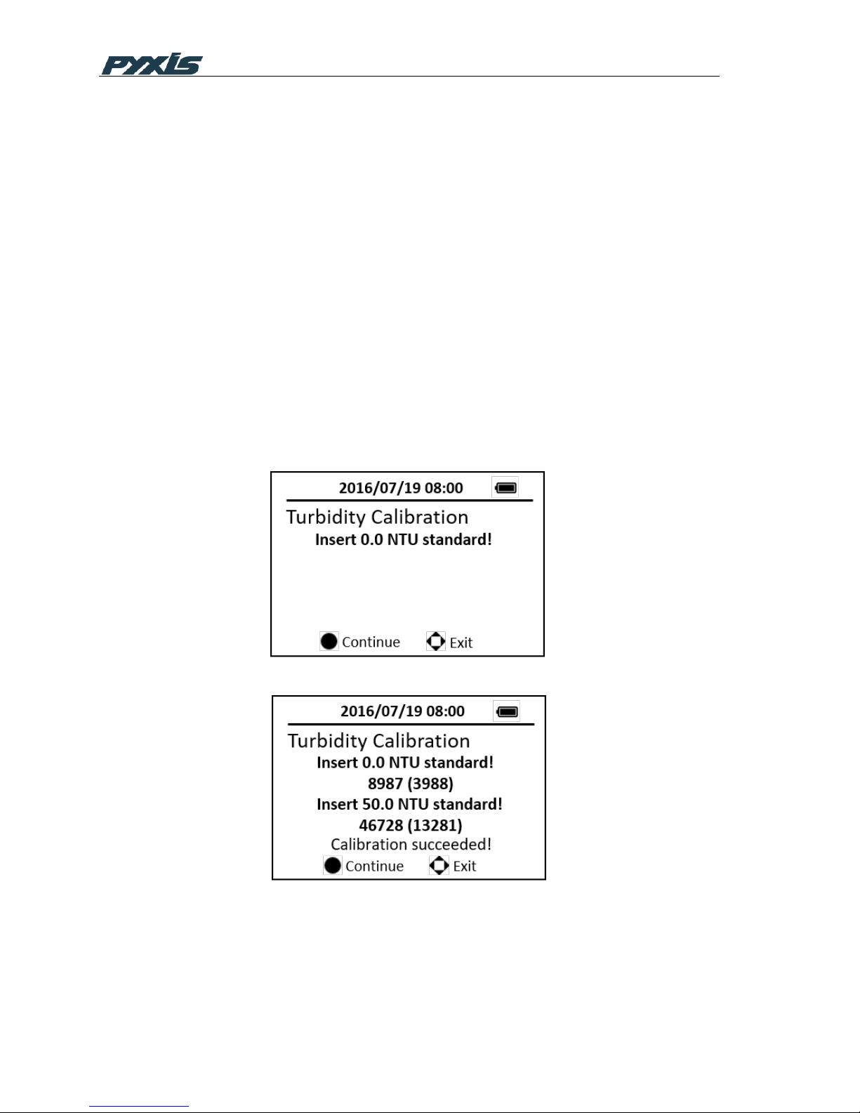
4. Press the CAL on the main page, then choose the Turbidity calibration and
press the OK button to launch the Turbidity calibration page. (Figure 20)
5. Press the OK key to measure the deionized water
6. Fill the 10 ml sample vial to above 10 ml mark with the 50 NTU standard.
Insert the sample vial to the sample vial compartment.
7. Press the OK key to measure the 50 NTU standard. Low range turbidity
calibration is successful
8. Press the OK key to continue high range turbidity calibration. If high range
turbidity calibration not required, press any other keys to exit. (Figure 21)
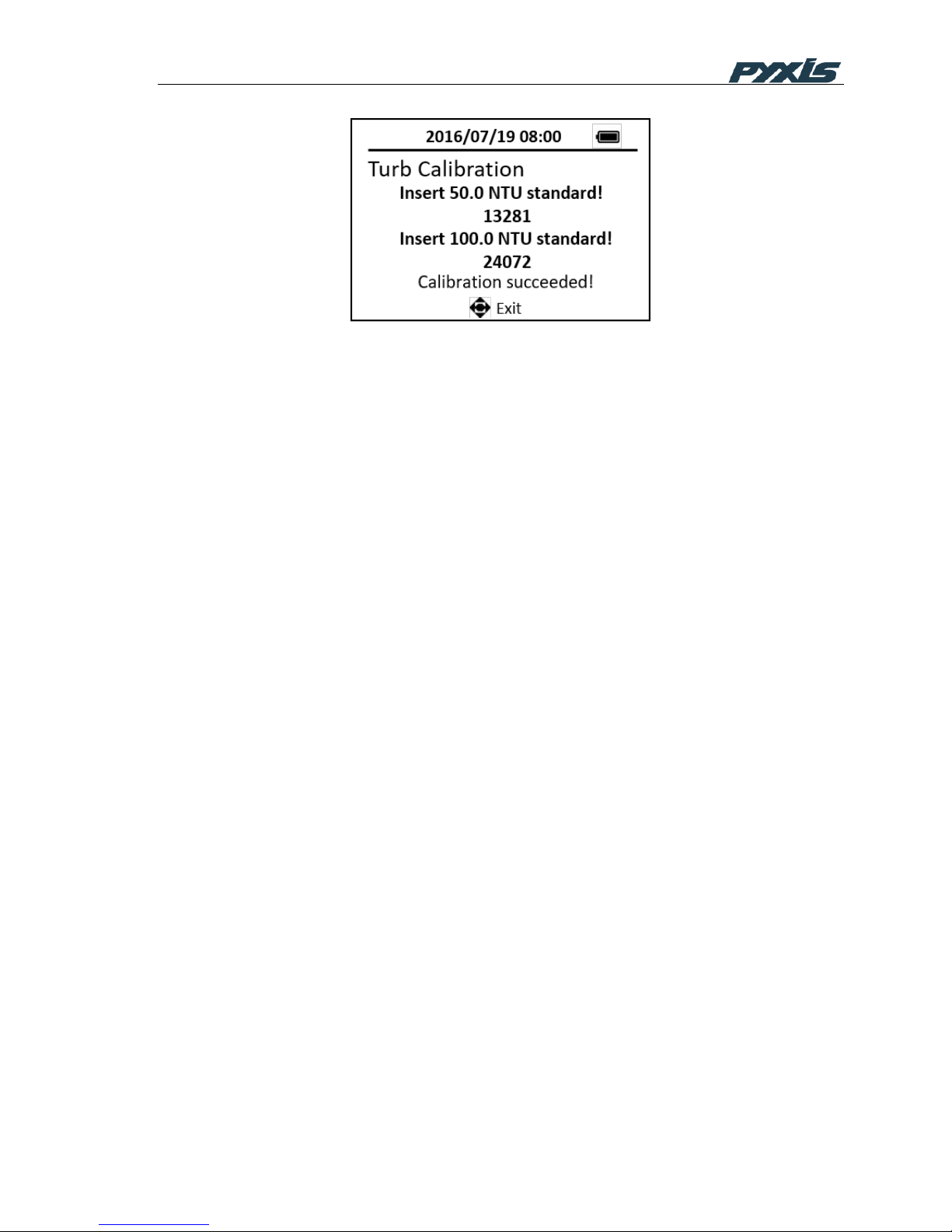
9. Fill the 10 ml sample vial to above 10 ml mark with the 100 or 200 NTU
standard. Insert the sample vial to the sample vial compartment.
10. Follow the message prompts, use the upper or down key to switch the
standard between 100 NTU and 200 NTU.
11. Press the OK key to measure the selected standard. High range turbidity
calibration is successful. (Figure 22)
12. Press any keys to exit.
Figure 20 Turbidity Calibration-1
Figure 21 Low Range Calibration
Page 31
29
Figure 22 High Range Calibration
Page 32
30
7 Absorbance Measurement
The following steps are used to measure the absorbance values of a sample:
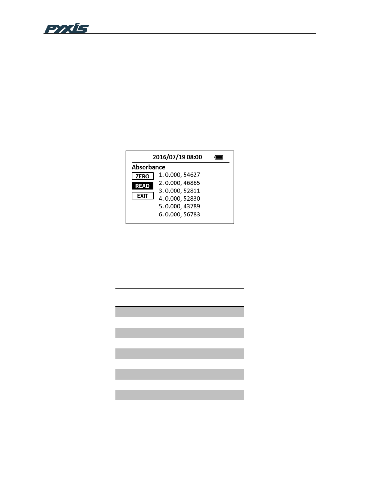
1. Press the ABS to launch the absorbance measurement page.
2. Place a vial filled with the blank sample in the sample vial compartment. Press
the ZERO button to zero the method.
3. Place a vial filled with the sample in the sample vial compartment. Press the
READ button to read absorbance. The absorbance values of first 6
wavelengths (Table 3) will be shown. Press the READ button again to show
the absorbance values of the last three wavelengths.
Figure 23 Absorbance Measurement
Press EXIT to return to the main page. Timing function for absorbance measurement may
not be available for some models.
Table 3 Wavelength of each channel
Channel
Wavelength (nm)
1
560
2
570
3
470
4
not used
5
455
6
525
7
365
8
630
9
420
Note that the absorbance values measured with the SP-910 is generally smaller than those
measured with a spectrophotometer equipped with a monochromatic light source or
detector. The SP-910 absorbance values should, however, linearly correlate with the
Page 33
31
absorbance values measured with the spectrophotometer. Thus, for any colorimetric
system, The SP-910 absorbance follows Lambert-Beer law.
8 Update SP-910 firmware via Bluetooth Interface
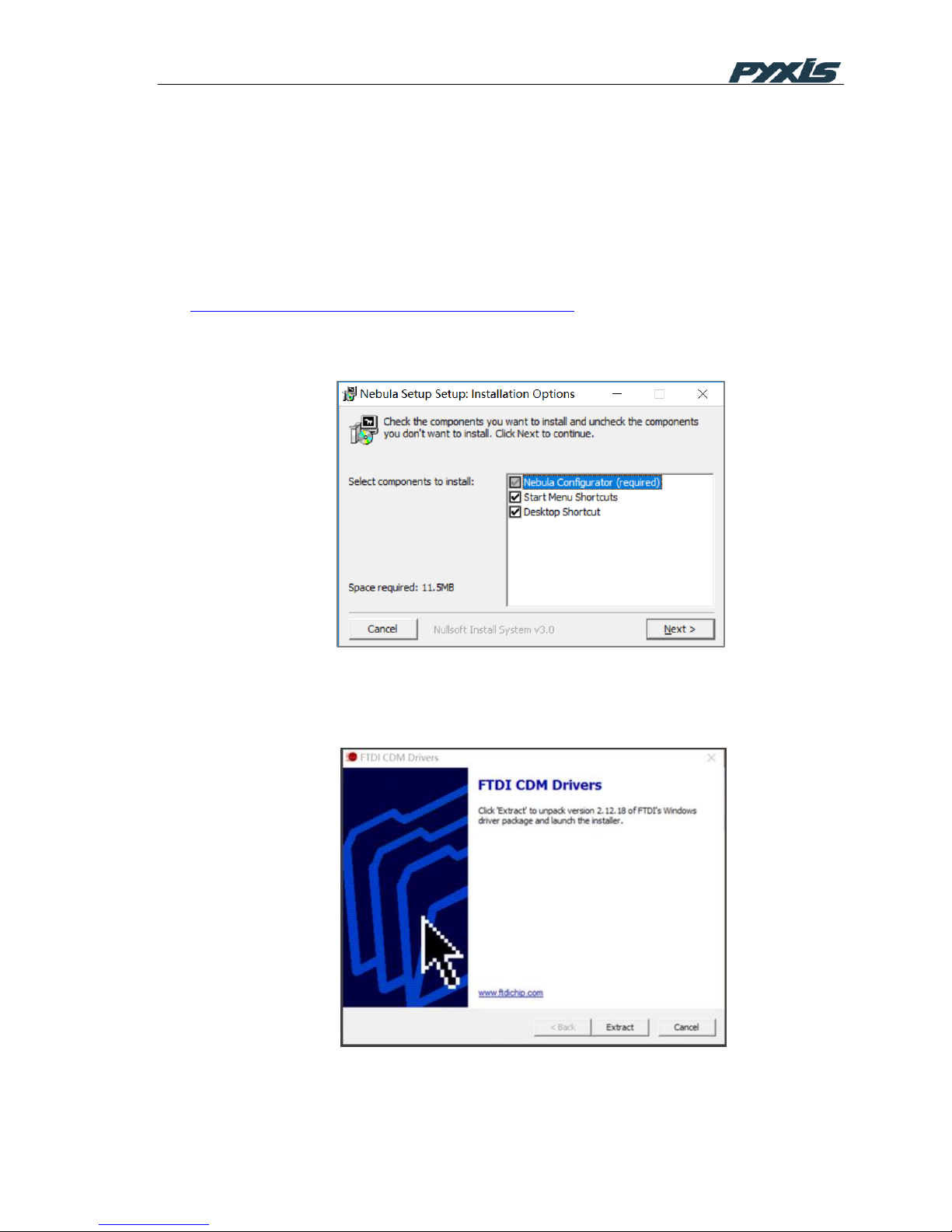
8.1 Download and Install the Latest Nebula Software
http://www.pyxis-lab.com/support.html#Software
1) Unzip the downloaded file and double click Nebula.exe to launch installation
Figure 24 Nebula Setup
2) The Bluetooth adapter driver software will be installed after Nebula PC software
installation
Figure 25 Bluetooth Adapter Driver Setup
Page 34
32
8.2 Turn on SP-910
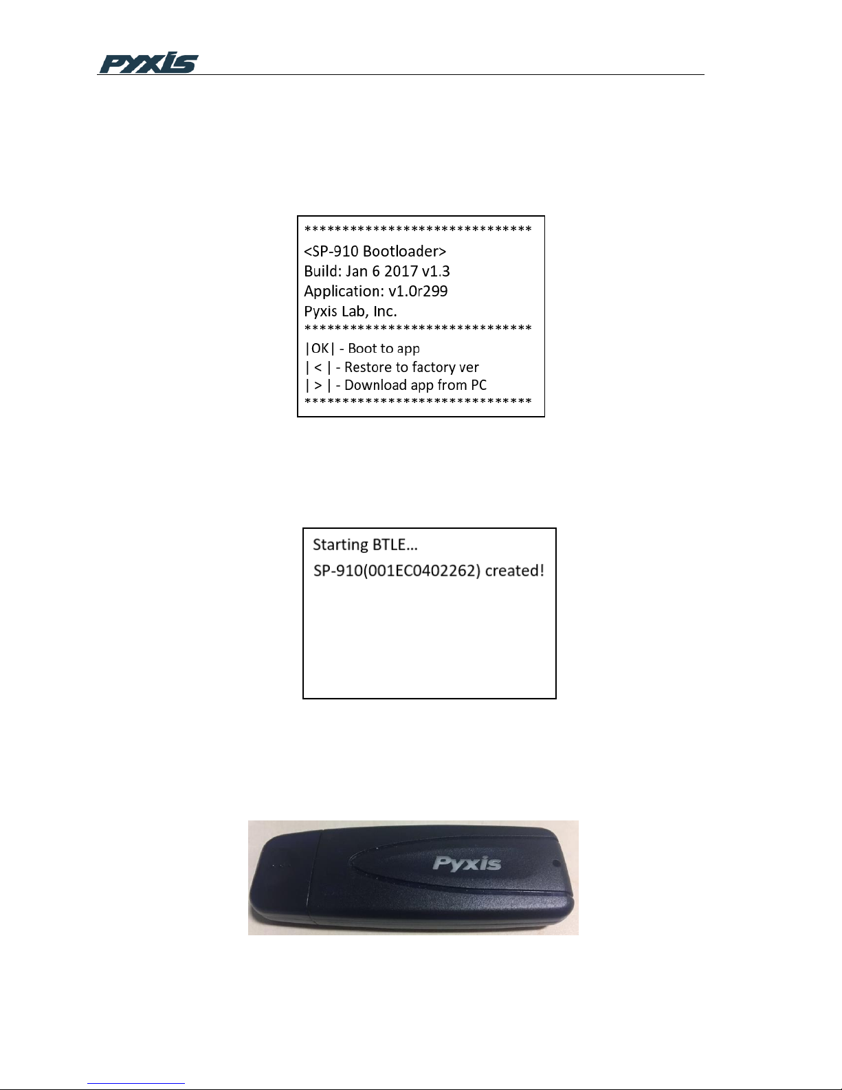
1) Long press OK button for 5 seconds to turn off the SP-910
2) Press LEFT button, then click OK button while holding down LEFT button
3) SP-910 displays below menu
Figure 26 Bootloader Menu
4) Click RIGHT button,SP-910 enters upgrading mode,SP-910 displays below menu to
indicate that it is ready to be connected by Nebula PC software
Figure 27 Bluetooth Ready
8.3 Connect Nebula to the SP-910
1) Plug the Bluetooth adapter into your PC USB port
Page 35
33
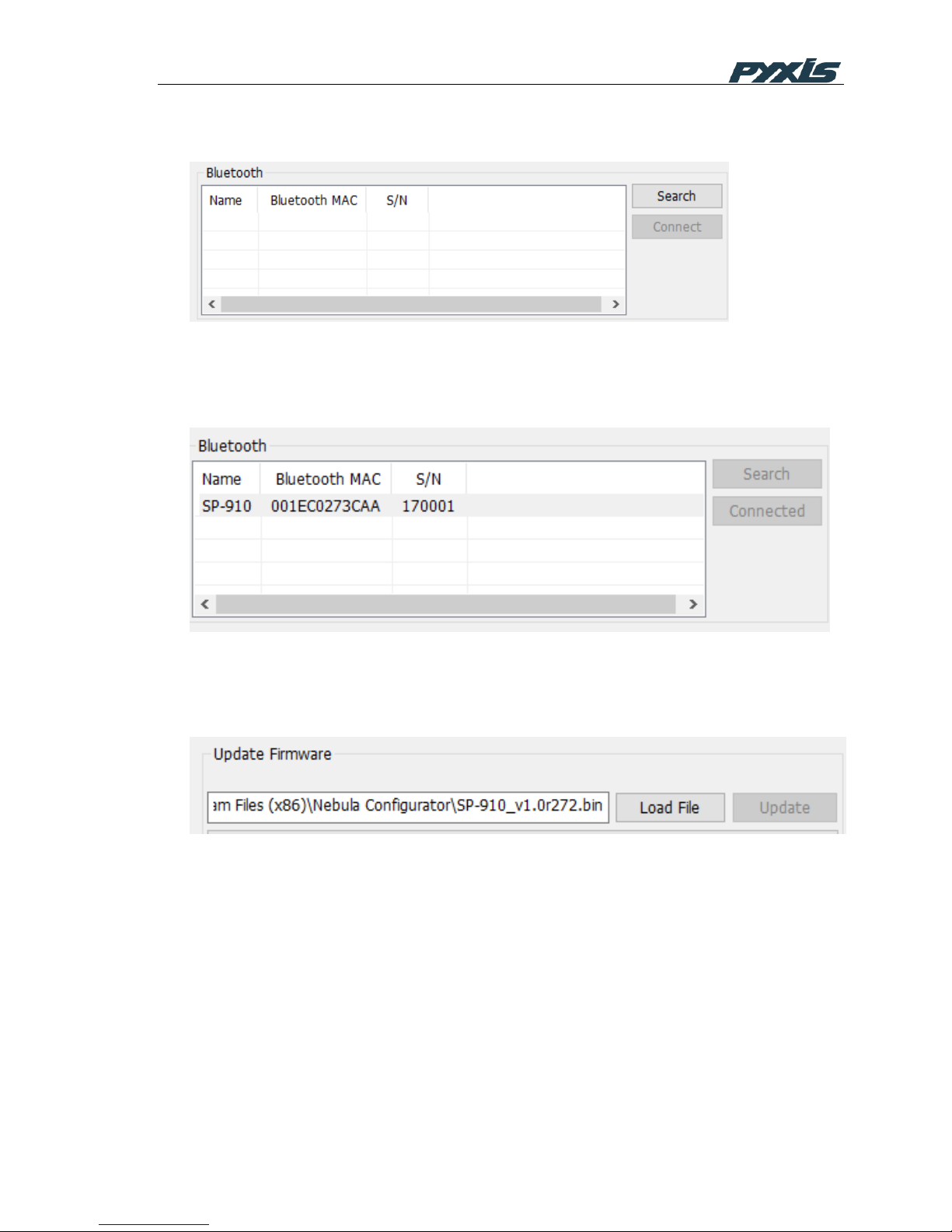
Open Nubula PC software, it searches device automatically. All available devices will be listed
in blow screen shot.
2) Nebula will connect to device automatically if it is the only device available. Otherwise
please select a device you want connected to. Please un-plug then plug Bluetooth
adapter and restart the Nebula PC software if no device was found.
3) Once the device is connected, click the Load File button to select SP-910 firmware file,
and click update button to start upgrading SP-910. It takes about 160 seconds to
complete the procedure. SP-910 starts the new firmware after upgrading.
9 Upgrade the ChemTreat Product List
1. Click Sync with CTVista+
2. Enter your CTVistaPlus user name and password to proceed to download the product
list
3. Click on Write to load the list to the SP-910
Page 36
34
10 Calibrate a ST-500 with SP-910
The SP-910 can be used to verify the result of inline Pyxis ST-500 and other probes by
measuring the sample water took from the inline probe sample line. The SP-910 can then
be used to calibrate the inline probes over the Bluetooth connection.
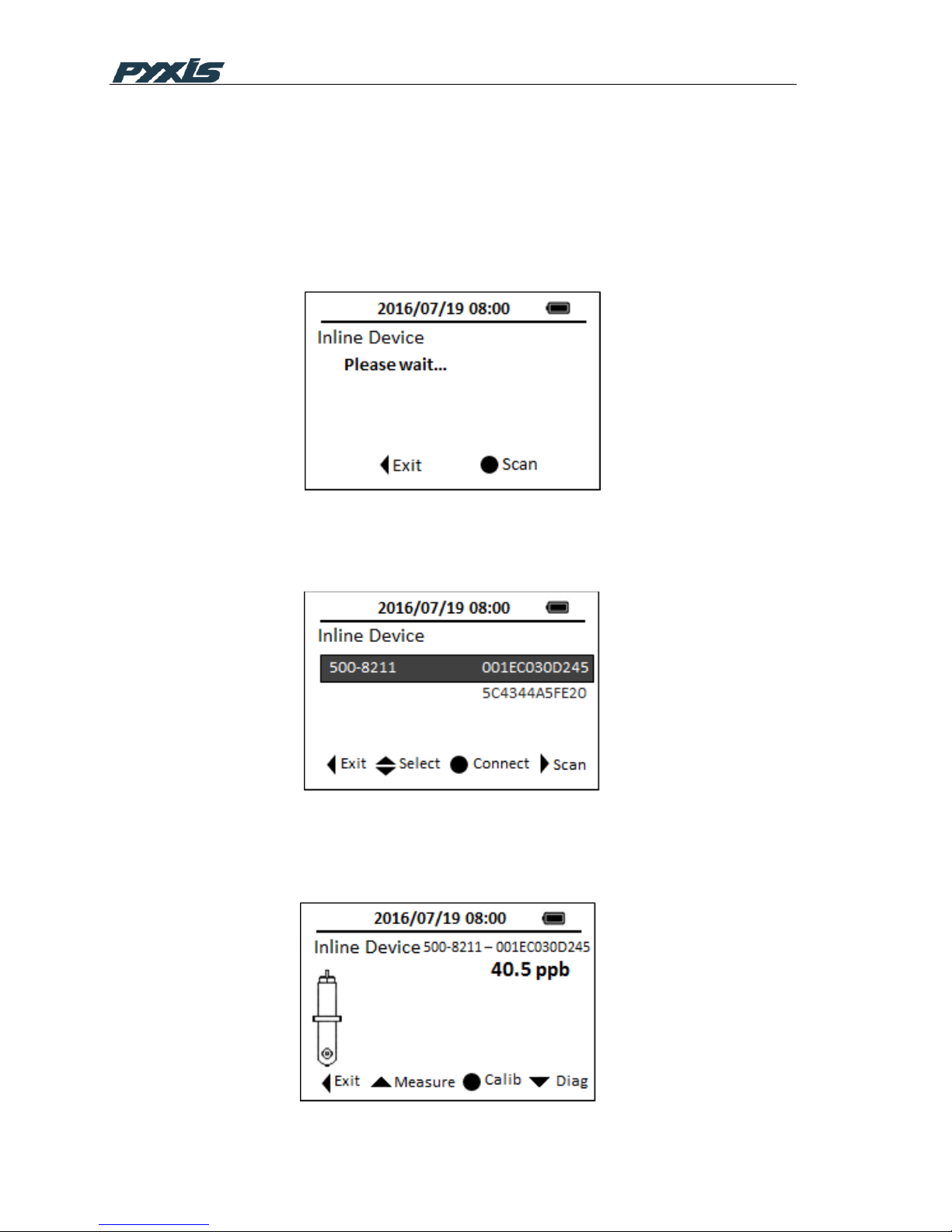
Choose the CAL ICON in main menu and select Inline Device, the following interface then
appears in the screen. SP-910 starts to scan devices via Bluetooth interface.
Figure 28 Scan Inline Device
Active inline probes will be listed in the following screen, use Up and Down key to select
the device you want to pair with, click OK key to connect to it.
Figure 28 Pair Inline Device
Once the connection is established, the SP-910 will read the latest reading from the
connected ST-500 and display the reading as shown in Figure 29.
Page 37
35
Figure 29 Read Inline Device
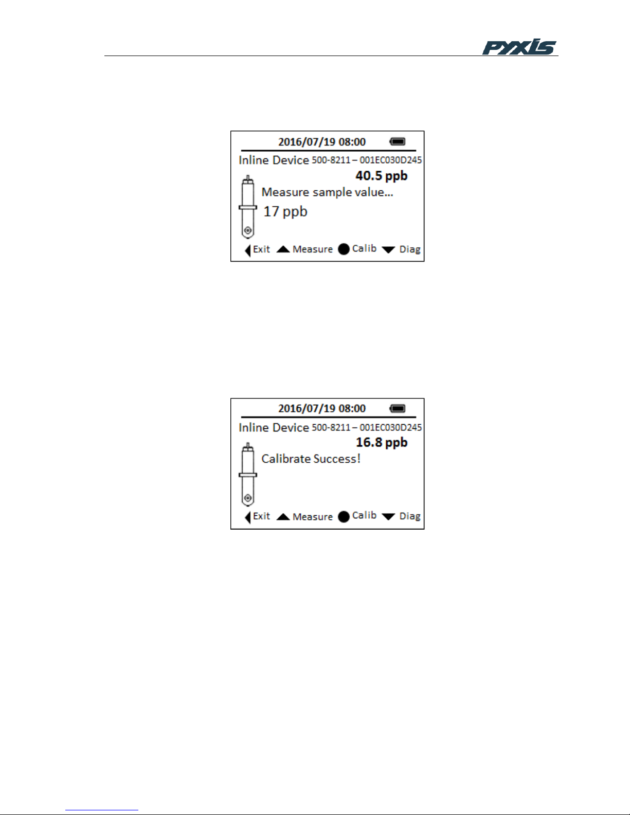
Use the SP-910 to measure the sample water by clicking Up key, as shown in Figure 30
Figure 30 SP-910 Measure Sample Water
Click OK key to send the calibration instruction to the ST-500 via Bluetooth connection.
After that, the connected ST-500 will be calibrated to the value measured by the SP-910.
The SP-910 will keep reading ST-500 every 4 seconds to verify if the calibration is
successful. Please note that it takes about a minute for the ST-500 to approach to the
calibrated reading.
Figure 31 Calibration Success
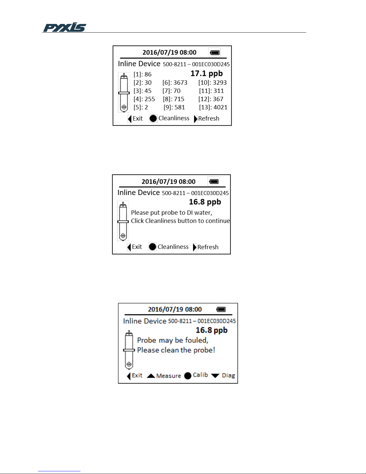
Click Down key to start diagnose ST-500 probe. As Figure 26 shows, a range of ST-500
operation parameters will be displayed. Furthermore, click OK button in diagnosis page to
check whether ST-500 is fouled.
Page 38
36
Figure 32 Inline Device Diagnosis Data
In the cleanliness check page, please put the ST-500 probe into DI water and then click
the OK button again to conduct cleanliness check.
Figure 33 Cleanliness Check
Figure 30 shows a probe may be fouled according to its diagnosis operational
parameters.
Figure 34 Probe is Fouled
Page 39

37
11 Maintenance
Use a soft cloth or lint free paper tissue to clean the sample vial compartment
periodically. Remove debris, scale, and deposit promptly.
Although The SP-910 is protected from water damage, it is a good practice to avoid
water entering the sample vial compartment and becoming trapping underneath the
navigational control pad. Deposits left behind when the water is evaporated could
affect Pyxis performance.
The SP-910should be stored in the temperature range of 0 to 140°F (-18 to 60°C ) and
relative humidity less than 85% at 106 °F (41 °C ). Do not leave the SP-910 in a parked
vehicle. The temperature inside a parked vehicle can reach above 150 °F in summer
and -20 °F in winter. Exposing the SP-910 to extreme temperature or humidity will
cause a gradual decay in performance of fluorescence measurements and require
more frequent calibrations.
During storage and transportation, do not leave a sample vial in the sample vial
compartment. Close the lid of the sample vial compartment during storage and
transportation.
Replace batteries when the SP-910 displays a warning message indicating LOW
BATTERY voltage. Remove batteries from the SP-910 battery compartment if the SP910 is going to be placed in storage for a long period time.
When the SP-910 is shipped, a desiccant pack is included in the desiccant
compartment underneath the cover of the battery compartment. It is recommended
that a new desiccant pack is replaced each time the batteries are replaced.
Page 40

38
12 Troubleshooting
The SP-910 will prompt a warning message if it detects an abnormal condition or
operation. On screen prompts direct the user to take appropriate corrective actions in
most cases.
If an unspecific error occurs or the SP-910 cannot be turned on, reboot the instrument
by taking a battery out of the battery holder and re-install the battery.
If the SP-910 has been idle for more than two months and cannot be turned on,
replace all four batteries with four new AA alkaline batteries.
A diagnostics page can be launched by press the SYS icon in the main page. The
software version and its associated hash code can be found in the diagnosis page.
Contact Pyxis professionals at [email protected] and provide with following
information to ensure high quality technical support.
Table 4 Contact Information
Items
Note
Contact Name
Phone
Email
Customer Name
Product Number (P/N)
Can be found on the product label on back of
product
Serial Number (S/N)
Can be found on the product label on back of
product
Firmware version
Can be found in diagnosis page
Problem Description
Capture warning message if applicable
Page 41

39
13 Appendix A.
Pyxis Method and Hach® Method Number (PRMP) Cross Reference
Abbreviated
Method
Name
Method Name
Corresponding Hach © method
Hach Method
Number
CL-F
F-Chlorine
Chlorine, Free, DPD, PRMP 9
8021
CL-T
T-Chlorine
Chlorine, Totoal, DPD, PRMP 9
8167
Cl2H
Cl2High
High Range DPD Chlorine, No
sample change needed
10070
CuBi
Cu_Bicinch
Copper, Bicinchoninate, PRMP 20
8506
DEHA
DEHA
DEHA, Iron Reduction Method for
Oxygen Scavengers, PRMP 25
8140
Ca
Ca
Calcium: Calmagite Colorimetric
Method, PRMP 29
8030
Mg
Mg
Magnesium: Calmagite
Colorimetric Method, PRMP 30
8030
FePh
Fe_phenanth
Iron, 1,10 phenanthroline, PRMP
33
8008
FeZi
FeZine
Iron, FerroZine, PRMP 37
8147
FeTp
FeTptz
Iron, TPTZ, PRMP 39
8112
MoHR
Mo_HighRange
Molybdenum, High Range,
Mercaptoacetic Acid, PRMP 44
8036
MoLR
Mo_LowRange
Molybdenum, Low Range, Ternary
Complex, PRMP 47
8169
NO2H
NO2H
Nitrite, High Range, Ferrous
Sulfate, PRMP 59
8153
NO2L
NO2L
Nitrite, Low Range, Diazotization,
PRMP 60
8507
PMoV
OPO4-MoV
Phosphorus, Reactive,
Molybdovanadate, GRMP 77
8114
OPO4
OPO4
Phosphorus, Reactive,
Orthophosphate Ascorbic Acid,
GRMP 79
8048
OrgP
Phosphonate
Phosphonates, Persulfate UV
Oxidation, PRMP 80
8007
PAmi
OPO4-Amino
Phosphorus, Reactive, Amino
Acid, GRMP 85
8178
ClO2
ClO2-DPD
Chlorine Dioxide, DPD, PRMP 112
10126
ClO2D
ClO2Direct
Chlorine Dioxide, Direct Reading,
PRMP7
8345
SiHR
SiHR
Silica, High Range,
Silicomolybdate, PRGM 89
8185
SiLR
SiLR
Silica, Low Range, Heteropoly
Blue, PRMP 90
8186
AZOL
Azole
Benzotriazole, UV Photolysis,
PRMP 3
8079
Page 42

40
SO4
SO4
Sulfate. PRMP 91
8051
POLY
Polymer
Turbidimetric method for anionic
polymers
N/A
FeMo
FeMo
Iron, for cooling water with
molybdenum-based treatment,
PRMP 38
8365
Cr6
Cr6
Hexavalent chromium, 1,5Diphenylcarbohydrzaide Method,
PRMP 13
8023
CrT
CrTot
ChromiumtotalAlkaline
Hypobromite Oxidation Method,
PRMP15
8024
NH3S
NH3Sal
Ammonia Salicylate Method,
PRMP 64
8155
NH2C
NH2Cl
Indophenol Method for
MonoChloramine, PRMP 110
10171
N2H4
N2H4
P-Dimethylaminobenzaldehyde
Method for Hydrazine, PRMP 31
8141
MnL
MnLow
Low Range Manganese PAN
Method, PRMP 43
8149
MnH
MnHigh
High Range Manganese,
Periodate Oxidation Method,
PRMP 41
8034
BLCH
Bleach
Direct Method measuring sodium
hypochlorite concentration
N/A
Al
Alumi
Aluminon Method for Aluminum,
PRMP 1
8012
F
Floride
SPADNS 2 Method for Fluoride,
PRMP 27
8029
CuL
CuPorp
Porphyrin Method for Copper,
PRMP 22
8143
Zn
Zinc
Zincon Method for Zinc, PRMP 97
8009
S2-
Sulfide
Methylene Blue Method for
Sulfide, PRMP 93
8131
CN
Cyanide
Pyridine-Pyrazalone Method for
Cyanide, PRMP 23
8027
NO3M
NO3M
Middle range nitrate, PRMP54
8171
NO3H
NO3H
High range nitrate, PRMP51
8039
Ni
Ni
PAN method for nickel, PRMP48
8150
CYAN
CYAN
Turbidimetric method for cyanuric
acid, PRMP 24
8139
pH
pH
Phenol red method for pH, PRMP
75
10076
Hach ® is a registered trademark of the Hach Company, Loveland, CO USA
 Loading...