

Page 1
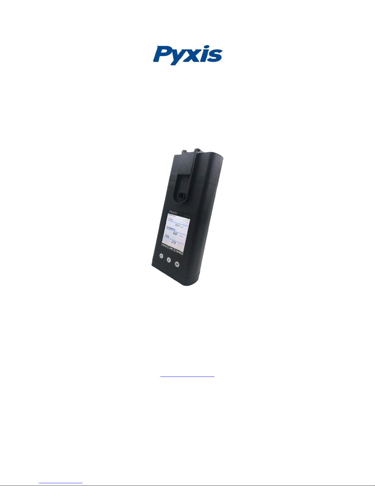
SP-710 Water Multimeter
Operation Manual
Jan. 23, 2019
Rev. A
US Patent: 9612221
Pyxis Lab, Inc.
1729 Majestic Dr. Suite 5
Lafayette, CO 80026 USA
www.pyxis-lab.com
© 2017 Pyxis Lab, Inc.
Pyxis Lab Proprietary and Confidential
Page 2

The information contained in this manual may be confidential and proprietary and is the property of Pyxis Lab, Inc.
Information disclosed herein shall not be used to manufacture, construct, or otherwise reproduce the goods
described. Information disclosed herein shall not be disclosed to others or made public in any manner without the
express written consent of Pyxis Lab, Inc.
Limited Warranty
Pyxis Lab warrants its products for defects in materials and workmanship. Pyxis Lab will, at its option, repair or
replace instrument components that prove to be defective with new or remanufactured components (i.e.,
equivalent to new). The warranty set forth is exclusive and no other warranty, whether written or oral, is expressed
or implied.
Device Warranty Term
The Pyxis warranty for SP-710 and SP-710B ‘device not including pH-ORP module’ term is thirteen (13) months from
original shipment from Pyxis. In no event shall the standard limited warranty coverage extend beyond thirteen (13)
months from original shipment date.
pH/ORP Module Warranty Term
The Pyxis warranty term for the pH/ORP module is six (6) months ex-works. This is a consumable module to SP-710
and SP-710B and will require scheduled replacements. Pyxis Lab recommends replacement of this module on a basis
of every 9-12 months for preventative maintenance. In no event shall the standard limited warranty coverage
extend beyond (6) months from original shipment date.
Warranty Service
Damaged or dysfunctional instruments may be returned to Pyxis for repair or replacement. In some instances,
replacement instruments may be available for short duration loan or lease.
Pyxis warrants that any labor services provided shall conform to the reasonable standards of technical competency
and performance effective at the time of delivery. All service interventions are to be reviewed and authorized as
correct and complete at the completion of the service by a customer representative or designate. Pyxis warrants
these services for 30 days after the authorization and will correct any qualifying deficiency in labor provided that the
labor service deficiency is exactly related to the originating event. No other remedy, other than the provision of labor
services, may be applicable.
Repair components (parts and materials), but not consumables, provided in the course of a repair, or purchased
individually, are warranted for 90 days ex-works for materials and workmanship. In no event will the incorporation
of a warranted repair component into an instrument extend the whole instrument’s warranty beyond its original
term.
Warranty Shipping
A Repair Authorization Number (RA) must be obtained from Pyxis Technical Support before any product can be
returned to the factory. Pyxis will pay freight charges to ship replacement or repaired products back to the customer.
The customer shall pay freight charges for returning products to Pyxis. Any product returned to the factory without
an RA number will be returned to the customer.
Pyxis Technical Support
Contact Pyxis Technical Support at [email protected] or 1-866-203-8397 (Mo-Fri 7:00AM-5PM MT)
Page 3

Pyxis SP-710 Multimeter Operation Manual 3
Table of Contents
1 Introducing the Pyxis SP-710 Multimeter .....................................................................................5
1.1 Features of the Pyxis SP-710 ......................................................................................................... 5
1.2 Specifications ................................................................................................................................ 6
1.3 Unpacking the Pyxis SP-710 .......................................................................................................... 6
1.4 Standard Accessories .................................................................................................................... 6
1.5 Optional Accessories ..................................................................................................................... 7
1.6 Dual Function Seal for the pH/ORP Cell ........................................................................................ 7
2 Using the Pyxis SP-710 ................................................................................................................8
2.1 Battery Installation ........................................................................................................................ 8
2.2 Turning the SP-710 ON and OFF ................................................................................................... 9
2.3 Turn on the pH/ORP Module Power ............................................................................................. 9
2.4 Using the SP-710 Control Keys .................................................................................................... 10
3 Multiple Parameter Measurement ............................................................................................ 10
3.1 PTSA and Conductivity Measurement ........................................................................................ 10
3.2 pH and ORP Measurement ......................................................................................................... 11
3.3 Temperature Measurement ....................................................................................................... 12
3.4 Free Chlorine Measurement ....................................................................................................... 12
3.5 Conductivity Temperature Compensation .................................................................................. 14
3.6 High Color and Turbidity Warning .............................................................................................. 14
3.7 pH Measurement Principle ......................................................................................................... 14
3.8 ORP Measurement Principle ....................................................................................................... 15
4 Calibrating the SP-710 ............................................................................................................... 15
4.1 PTSA Standalone Calibration (2 point with zero) ........................................................................ 16
4.2 Combined Calibration Procedure ................................................................................................ 16
4.3 Standard Conductivity Calibration (500, 1000, 2500, or 5000 µS) ............................................. 18
4.4 User-Defined Conductivity Calibration Procedure...................................................................... 19
5 pH and ORP Calibrations ........................................................................................................... 20
5.1 pH Electrode Calibration ............................................................................................................. 21
5.1.1 One-Point Calibration ......................................................................................................... 21
5.1.2 Second-Point Calibration .................................................................................................... 21
5.1.3 Third-Point Calibration ........................................................................................................ 21
5.2 ORP Calibration ........................................................................................................................... 22
6 Chlorine Calibration .................................................................................................................. 23
6.1 Chlorine Reagent Blank (Zero) Calibration .................................................................................. 23
6.2 Chlorine Slope Calibration .......................................................................................................... 24
7 Device Information and Diagnosis ............................................................................................. 24
8 Device Maintenance ................................................................................................................. 25
9 Replacing the pH/ORP module (Part #50313)............................................................................. 26
9.1 Module Replacement .................................................................................................................. 26
Page 4

Pyxis SP-710 Multimeter Operation Manual 4
9.2 Bluetooth Pairing Your pH/ORP Module to SP-710 .................................................................... 27
10 Bluetooth Connection of SP-710 to Devices ............................................................................... 27
11 Calibrate ST-500 with SP-710 .................................................................................................... 28
12 REGULATORY APPROVAL .......................................................................................................... 30
13 Appendix. Cleaning Kit .............................................................................................................. 31
Page 5

Pyxis SP-710 Multimeter Operation Manual 5
1 Introducing the Pyxis SP-710 Multimeter
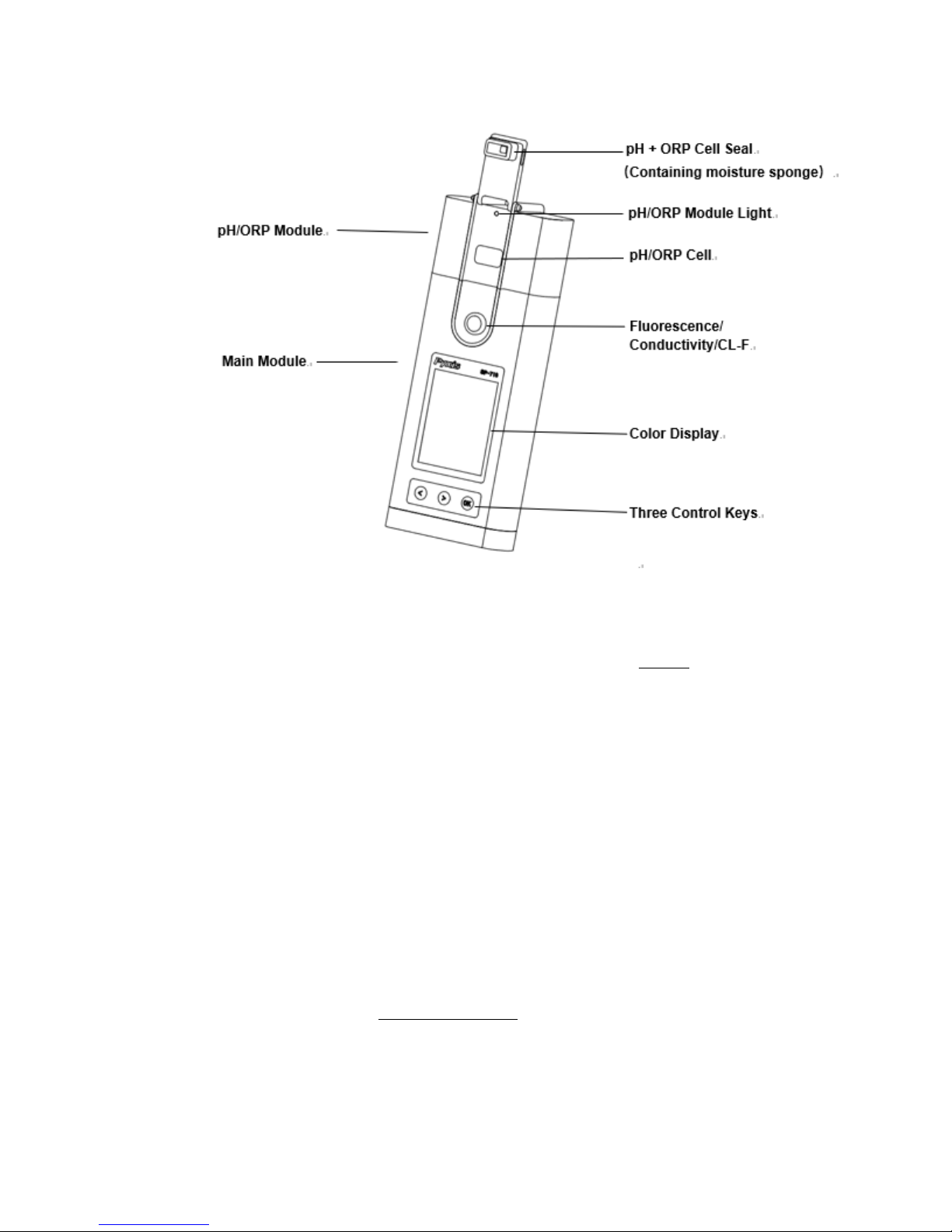
The Pyxis SP-710 is a handheld multimeter that measures five key parameters. It is a cuvette-less
device. Less than 5 ml water sample is needed to fill the two sample cells for the measurement.
• pH
• Conductivity
• PTSA (Pyrene Tetrasulfonic acid Tetra Sodium)
• ORP
• Temperature
• Free and Total Chlorine (TMB Method)
1.1 Features of the Pyxis SP-710
The SP-710 includes the following features:
• Breakthrough technology combining PTSA with conductivity and pH/ORP in a single rugged
meter.
• The PTSA measurement uses custom signal processing algorithms to compensate for sample
color and turbidity interference.
• Modular pH/ORP design with extra-large junction capacity providing increased service life.
• Easy replacement of the pH/ORP module without the need to open the meter enclosure.
• The pH/ORP module can be used wirelessly and independent of the main module.
• Long battery life: 10,000+ readings.
• Self-diagnosis during calibrations.
Page 6

Pyxis SP-710 Multimeter Operation Manual 6
1.2 Specifications
Specifications are subject to change without notice. Contact Pyxis ([email protected]) for
an updated specification list.
Item
Specification
Analysis
PTSA
0-300 ppb, ±1 ppb or 1% precision
Conductivity
1-15,000 µS/cm with ATC. ±1% or ±1 µS/cm precision
pH
0-14 with ATC, ±0.01 pH unit precision
ORP
±1500 mV, ±1 mV precision
Temperature
0-70 °C (32-160 °F), ±0.1 °C (±0.2 °F)
Chlorine
0 – 2.2 ppm free or total, +/- 0.01 precision
Storage Temperature
-10 °C – 50 °C (-4 - 140° F)
Operational Temperature
0 °C – 40 °C (32 - 104° F)
Sensor Module
pH/ORP, replaceable – recommended every 9-12 months
Typical Sensor Life
pH/ORP - 1 year
PTSA/Conductivity - 5 years
Protection Grade
IP67, Fully Dustproof and Waterproof
Regulation
CE
Display
Color LCD, Visible Under Direct Sunlight
Power Supply
4 AA alkaline batteries
Typical Battery Life
10,000 readings
Dimension (L x W x H)
208 x 80 x 45 mm (8.19 x 3.15 x 1.77 inches)
Weight
520 g (1.15 lbs) batteries excluded
1.3 Unpacking the Pyxis SP-710
Remove the instrument and accessories from the shipping container and inspect each item for
any damage that may have occurred during shipping. Verify that all items listed on the packing
slip are included. If any items are missing or damaged, please contact Pyxis Customer Service at
[email protected]. During shipping and storage after production, a sponge wetted with the
KCl based pH storage solution is placed in the pH/ORP cell. You may also observe some residual
dry storage solution leaving white potassium chloride crystal in the surrounding areas of the cell.
Please rinse the cell with a water sample before use.
1.4 Standard Accessories
The following accessories are included in the SP-710 package:
• Four (4) AA alkaline batteries
• Bluetooth USB adapter (Part # MA-NEB)
The full instrument manual is available for download at www.pyxis-lab.com/support.html
Page 7
Pyxis SP-710 Multimeter Operation Manual 7
1.5 Optional Accessories
The following optional accessories can be ordered from Pyxis Customer Service,
Accessory
Item number
Replacement pH/ORP Module - Bluetooth
50315
Carrying Case for SP-710
MA-700
100 ppb PTSA + 1000 S/cm (KCl) combined standard
PTSA-1010
220 mV ORP Calibration Standard
ORP-220
100 ppb PTSA Calibration Standard
PTSA-100
pH 4-7-10 Calibration Combination Kit
57007
1000uS Conductivity Calibration Standard
57008
1.6 Dual Function Seal for the pH/ORP Cell
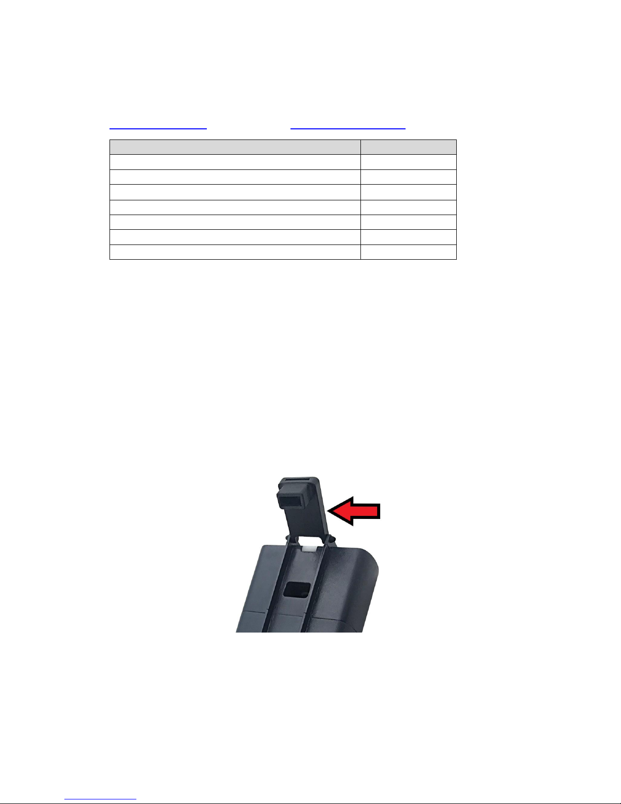
The SP-710 pH/ORP seal (Figure 1) has two functions:
• When the multimeter is in storage, the rubber seal seals the pH/ORP cell, maintaining a
moist environment for the electrodes.
• The seal contains a permanent magnet. When being brought close to the front end of the
module, the seal turns on pH/ORP module power.
Page 8
Pyxis SP-710 Multimeter Operation Manual 8
Figure 1. Seal in the open position
Please fill the pH/ORP cell with 1 ml of the pH 4 buffer solution or pH electrode storage solution
at all times when not using the pH/ORP cell. NOTE - The sponge soaked with the pH storage
solution in the pH/ORP helps prolong the life of the pH/ORP module.
2 Using the Pyxis SP-710
2.1 Battery Installation
The main module of the SP-710 is powered by four AA alkaline batteries. Typical battery life is
10,000 measurements, or 10 months. When the battery capacity is critically low, the SP-710
displays a LOW BATTERY warning for five seconds, and then automatically turns off.
The SP-710 does not turn itself on automatically after the new battery installation. To turn on the
SP-710 after new battery installation, press the OK key momentarily and release.
Maintaining SP-710 date and time during battery installation: The SP-710 has a calendar timer.
To prevent the calendar from being reset to the default date and time (01/01/1970, 00:00:00),
install the four new batteries within four minutes after the old batteries are removed from the
battery compartment.
The SP-710 date and time is synchronized with your PC automatically when connected with
uPyxis© app via Bluetooth adapter provided.
Page 9
Pyxis SP-710 Multimeter Operation Manual 9
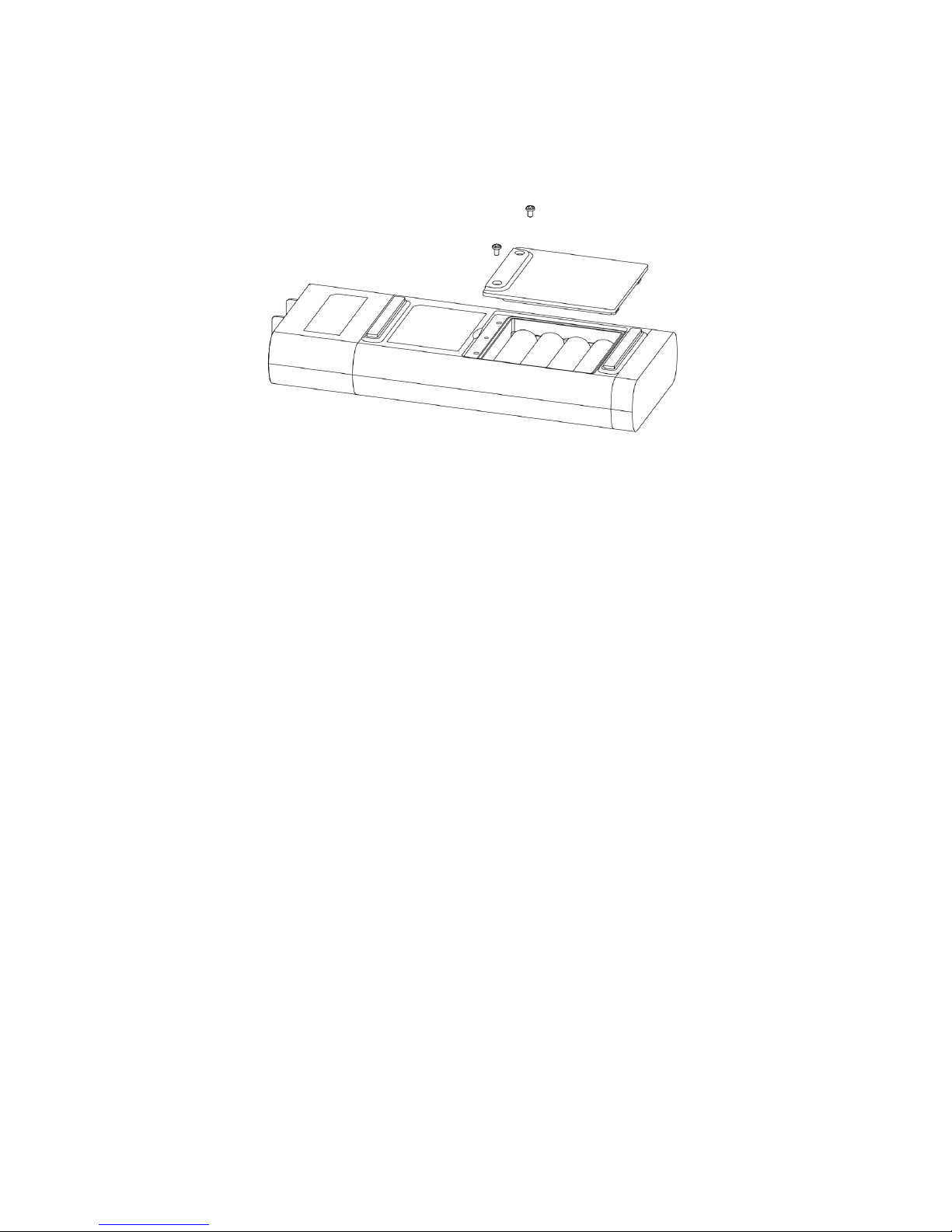
The SP-710 battery compartment, shown in Figure 2, is on the back side of the instrument.
Batteries are held in place by a cover secured with two Phillips-head screws.
Figure 2. The SP-710 battery compartment
Use the following procedure to install new batteries:
1. Remove the battery compartment cover by loosening the two screws.
2. Remove the old batteries and dispose of properly.
3. Following the positive and negative terminal signs in the compartment bottom, snap four
new AA alkaline batteries firmly into the battery holder.
4. Replace the battery compartment cover and ensure that the sealing O-ring is lying flat on
the battery holder. NOTE: Failure to properly seat the O-ring may result in water damage
to the meter.
5. Fasten the two screws.
2.2 Turning the SP-710 ON and OFF
To turn on the SP-710: Press the OK key momentarily and release.
To turn off the SP-710: Press and hold the OK key for three seconds. Release the OK key when
the LCD display turns off.
The SP-710 turns itself off after 30 seconds without user interaction detected. This is done to
conserve battery life.
2.3 Turn on the pH/ORP Module Power
The module has a permanently sealed 3.7 V lithium battery. The module is turned on by rotating
the pH/ORP seal to touch the front face of the module. A sealed magnet within the rubber seal
Page 10
Pyxis SP-710 Multimeter Operation Manual 10
will trigger the module power circuit. The pH/ORP module will turn itself off when either
commanded by the main SP-710 module or automatically based on the idle time limit. The
purpose for this design is to extend battery life.
If pH/ORP measurement is not needed, the module does not need to be turned on.
2.4 Using the SP-710 Control Keys
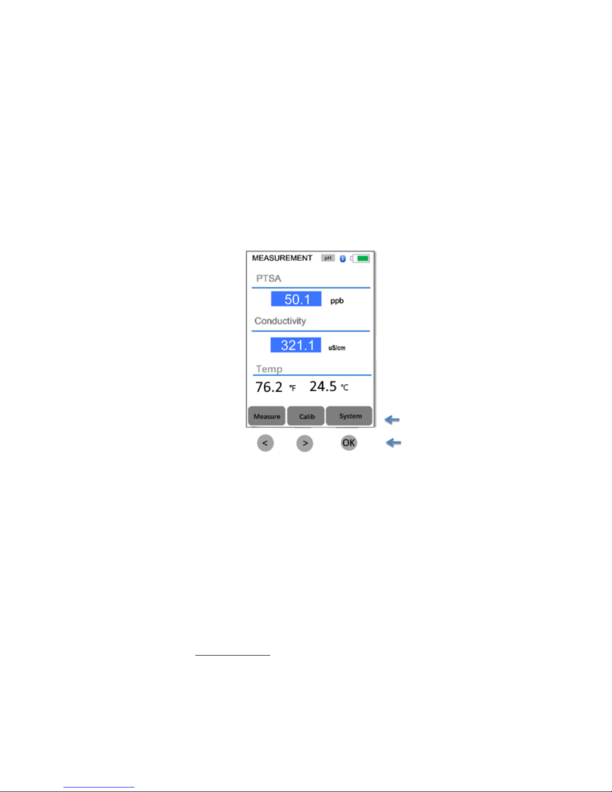
The SP-710 has three control keys, as shown in Figure 3. The left ( < ), right ( > ), and OK keys are
used to launch actions indicated on the LCD screen directly above the keys. Note that the LCD
screen is not a touch-enabled device; the labels above the keys indicate the function associated
with the keys, and functions can be changed in different operation modes.
Figure 3. Control keys and associated functions
3 Multiple Parameter Measurement
3.1 PTSA and Conductivity Measurement
When powered on, the SP-710 is in the measurement mode of PTSA and Conductivity (as shown
in Figure 3 above).
A water sample should be transferred to the PTSA cell using a pipette, or the cells can be filled
directly from a sample bottle.
Rinse cells before measurement. Before beginning a measurement, use some of the sample water
to rinse the cells at least three times.
Allow five seconds for the SP-710 to reach stable readings. The time required to reach a stable
reading may be slightly longer if the water sample temperature is significantly different than the
Page 11
Pyxis SP-710 Multimeter Operation Manual 11
environmental temperature at which the SP-710 had been equilibrated (stored). The values will
be displayed in white with a blue background if a stable value is reached (Figure 3).
For a sample with conductivity in the range of 100 to 6000 S/cm, the measured value should be
stabilized in the range of 98–102 to 5940–6060 S/cm, respectively. For a sample containing 100
ppb PTSA, the measured PTSA should be stabilized within the range of 98–102 ppb.
3.2 pH and ORP Measurement
Follow the following steps to measure pH and ORP:
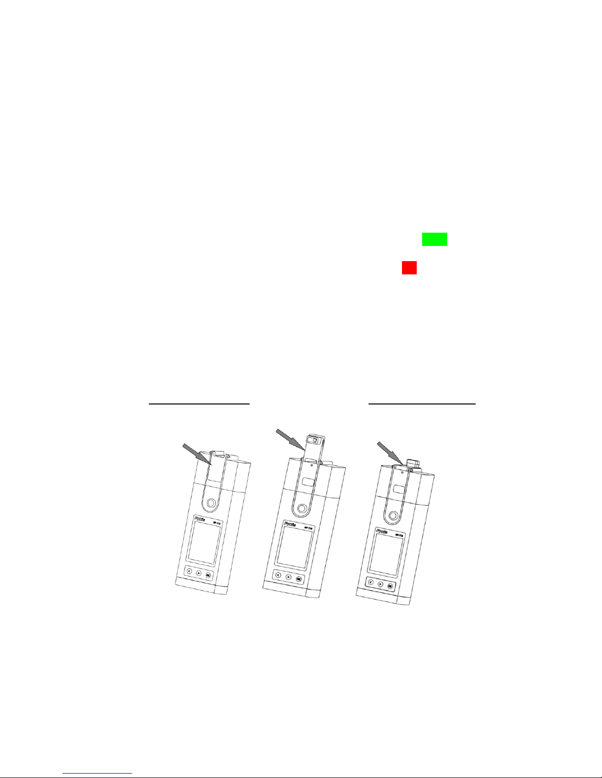
1. Lower the rubber seal down to touch the front face of the pH/ORP module (Figure 4). This is
to power on the module. The indicator light of the module will be green and flashing when
powered on. After the module is turned on, the seal can be positioned anywhere desired. If
the module battery capacity is low, the indicator light will flash red.
2. Rinse the pH/ORP cell and fill in the sample water.
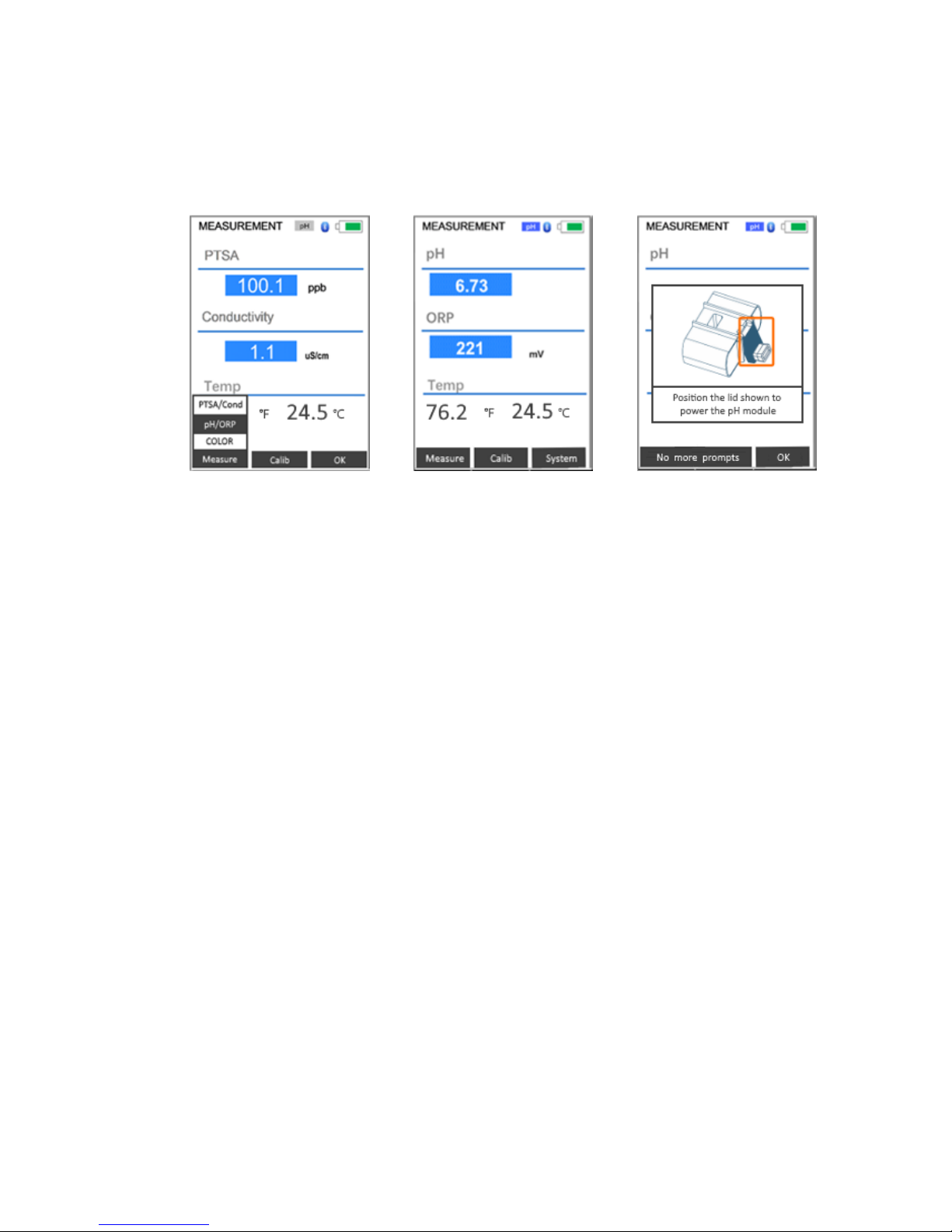
3. Press Measure (the < key). A selection menu will be shown as in Figure 5. Press Measure
again to highlight pH/ORP. Press OK to start pH and ORP measurement. The pH and ORP
values will be updated every two seconds. The values will be displayed in white with a blue
background if a stable value is reached (Figure 5).
OFF/CLOSED POSITION POWERED ON POSITION
Figure 4. Turn on pH/ORP module with the seal
Page 12
Pyxis SP-710 Multimeter Operation Manual 12
If step 3 is carried out to launch pH/ORP measurement from the main module without turning on
the pH/ORP module first (i.e., skipping step 1), an instruction message will be promoted on the
screen showing how to turn on the pH/ORP module (Figure 7). In this case, please turn on the
pH/ORP module by lowering the seal according to the message shown.
Figure 5. Select pH/ORP
measurement
Figure 6. Display pH and ORP
values
Figure 7. Instruction to turn on
pH/ORP module
A erroneous pH value could be obtained if the module has been stored dry without the protection
of the pH electrode storage solution for a long period. In this case, please fill the module cell a pH
storage solution to wet the electrode for 30 minutes before use. If the storage solution is not
available, please use the sample water to hydrate the electrode for 30 minutes.
3.3 Temperature Measurement
The SP-710B has two platinum RTDs located in the PTSA/Conductivity cell and the pH/ORP cell.
The temperature sensors are individually calibrated in the factory and does not need to be
calibrated during use. The temperature values measured is used in the conductivity temperature
compensation and in converting the measured cell potential to the pH value at the sample
temperature.
3.4 Free Chlorine Measurement
The Pyxis SP-710 free chlorine method is based on the USEPA-accepted tetramethylbenzidine
(TMB) chemistry for free chlorine analysis. The solidified reagent deposited inside a capped 2-ml
disposable pipette contains TMB and a pH buffer. When a water sample is withdrawn to the
pipette, the TMB reagent dissolves and reacts with free chlorine in the sample to form a yellow
solution. The SP-710 measures the absorbance value of the resulted yellow solution to determine
the free chlorine concentration. NOTE - Pyxis Lab is finalizing development of a Total Chlorine
pipette (TMB method). Once complete this additional reagent will be available for direct
measurement of total chlorine with SP-710.
Follow the procedure to measure free chlorine:
Page 13
Pyxis SP-710 Multimeter Operation Manual 13
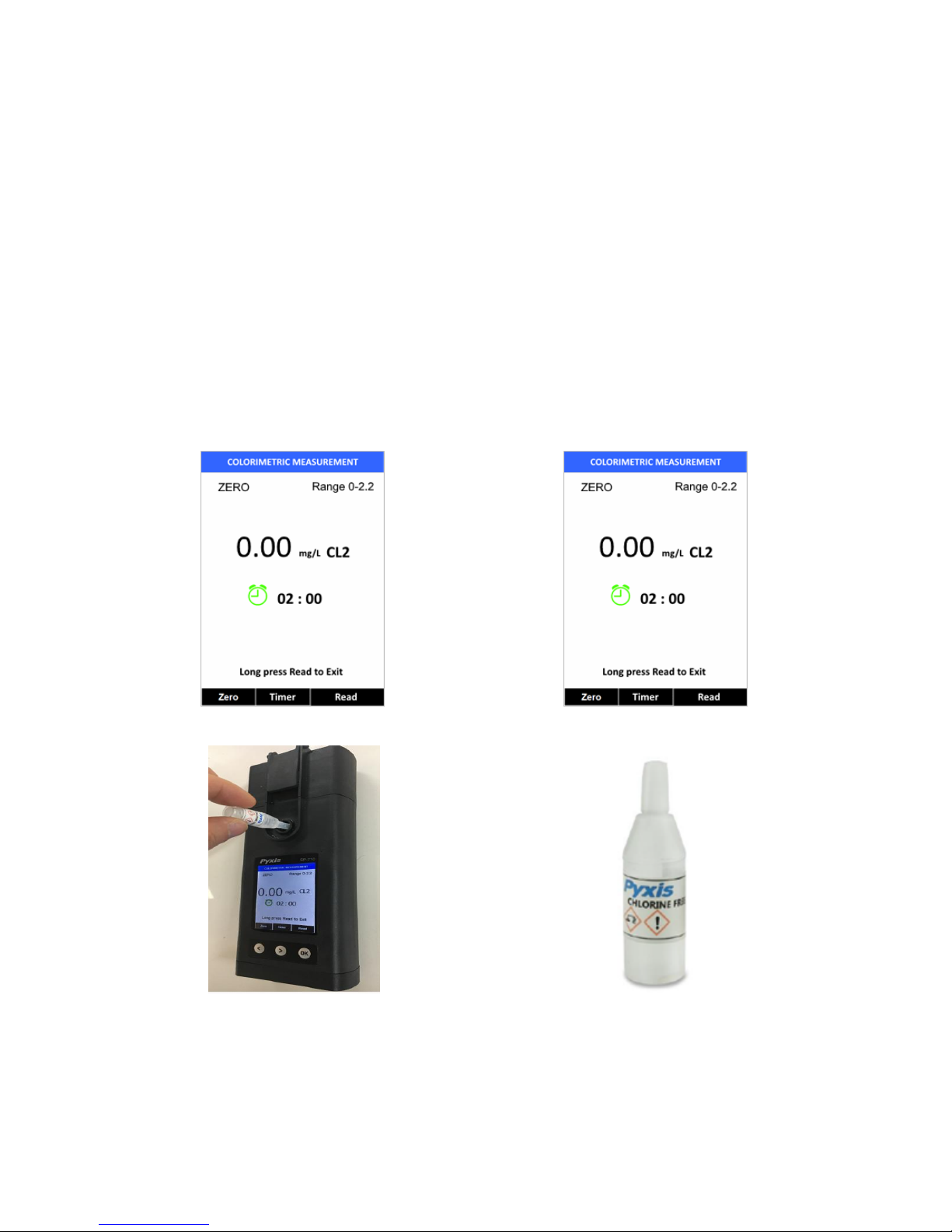
1. Press Measure (the < key) to launch the measurement selection menu. Press the < key twice
to highlight COLOR in the selection. Press OK to select the colorimetric screen (Figure 8).
2. Rinse the PTSA/Conductivity cell with the sample. Fill the sample cell with the sample.
3. Click Zero.
4. Withdraw sample water from the sample cell into the reagent pipette. Once the sample has
been drawn into the reagent pipette, shake the pipette or squeeze the sample back into the
sample cell several times allowing the reagent to fully dissolve.
5. Click Timer, the SP-700 starts 2-minute counter down timer.
6. The SP-700 will continuously display the free chlorine concentration, click Stop to stop
measurement if the real-time readings remain steady or you may wait for the 2-minute timer
to end. RECORD FINAL VALUE as ppm FREE CHLORINE.
Figure 8. Colorimetric screen for chlorine measurement
Figure 9. Zero on sample before reagent step
Figure 10. Withdraw sample to the reagent pipette and TMB Free Chlorine Pipette (Part #31053 -100/pack)
Page 14

Pyxis SP-710 Multimeter Operation Manual 14
3.5 Conductivity Temperature Compensation
The displayed conductivity value is automatically corrected to the nominal value at the reference
temperature 25.0 °C using the sample temperature measured. The commonly used linear
correction equation is used:
Conductivity at 25 °C = (Conductivity at T
measured
) / [1 + 0.02(T
measured
– 25)],
where T
measured
is the sample temperature in degrees Celsius.
3.6 High Color and Turbidity Warning
The SP-710 has extra channels to measure sample turbidity and color to automatically
compensate for sample color and turbidity interference. If sample turbidity and color values
determined are too high and beyond the compensation range, a PTSA measurement warning is
displayed. In this case, the sample should be pre-filtered for PTSA measurement.
3.7 pH Measurement Principle
The SP-710 uses the standard electrochemical cell for the pH measurement. The cell consists of
a glass electrode and an Ag/AgCl reference electrode. Potassium chloride (KCl) electrolyte filling
gel is sealed in the Ag/AgCl electrode.
The amount of reference electrolyte in the SP-710 is significantly larger than that used in a
common laboratory pH electrode. This reduces the chance of the filling solution being diluted or
contaminated and increases the electrode life.
The pH value is calculated from the measured cell potential (EMF in mV):
pH = EMF / S(T) + pHo
S(T) in the above equation is the calibration slope and is theoretically equal to:
0.1986(T + 273.15)
where T is temperature in degrees Celsius.
S(T) has a theoretical value of 59.17 mV at 25 oC. pHo is the calibration intercept. The calibration
slope S(T) at the nominal temperature 25.00 oC and the intercept pHo are determined in the twopoint or three-point calibration procedure. pHo is determined as well in the singe-point pH 7.00
calibration.
The temperature value measured by the SP-710 is used in the above equation to calculate the pH
value at the measurement temperature. Note that the temperature compensation involved in
the pH value calculation is quite different from that in the conductivity measurement. The
temperature-compensated conductivity value is a would-be value at the reference temperature
25 oC, while the pH value displayed by the SP-710 is the true pH value at the sample temperature.
Page 15

Pyxis SP-710 Multimeter Operation Manual 15
3.8 ORP Measurement Principle
The SP-710 measures the sample ORP with the platinum electrode and the Ag/AgCl reference
electrode in the pH/ORP cell. The pH measurement and the ORP measurement share the same
reference electrode. Reporting an ORP value without specifying the reference scale has no
meaning. The ORP value reported by the SP-710 could be referenced to the standard hydrogen
electrode (SHE), i.e., in the unit of Eh, or an Ag/AgCl electrode. The value displayed by the SP-
710 depends on the ORP value of the ORP standard used in the calibration.
If the ORP value of the standard is referenced to the standard hydrogen electrode (SHE), the ORP
value reported by the SP-710 is SHE-based, i.e., in the unit of Eh. If the ORP value of the standard
is referenced to the Ag/AgCl (3M KCl) electrode, the ORP value reported by the SP-710 is
referenced to the same, commonly noted as (Ag/AgCl, 3M KCl).
The ORP electrode is calibrated using the Zobell’s standard using the value of 221 mV at 25 o C
before shipping. The default ORP scale of the SP-710 before a user calibration is the Ag/AgCl (3M
KCl).
It is difficult to measure ORP of a field sample accurately and precisely. ORP of water samples with
low conductivity and low redox buffer capacity, such as unchlorinated surface water, is even more
difficult to measure. If the SP-710 is exposed to an extremely high (>600 mV) or extremely low (<
-200 mV) ORP sample, rinse the pH/ORP cell excessively when switching to measure a lower or
higher redox buffer capacity sample is necessary.
The dissolved oxygen in the sample can contribute to the ORP value measured. To measure a
sample that has not be equilibrated with the ambient air, a slow and small upward drifting to
more positive ORP value is normal.
For a typical cooling water sample treated with oxidizing biocides, a ± 20 mV accuracy and ± 10
mV precision can be expected.
4 Calibrating the SP-710
The PTSA, pH, ORP, and conductivity measurements can be calibrated separately using the
corresponding standards.
PTSA calibration requires the 100, 200, or 300 ppb PTSA standard solution. A standard with
conductivity value 500, 1000, 2500, or 5000 µS can be used to calibrate conductivity. Optionally,
you can use a standard with any conductivity value in the range of 500 to 5000 µS, such as the
commonly used 1412 (or 1413) µS standard, to calibrate the SP-710. For convenience, the SP-710
can be calibrated using a combined standard with 100 ppb PTSA + 1000 µS KCl conductivity
available from Pyxis.
Page 16

Pyxis SP-710 Multimeter Operation Manual 16
4.1 PTSA Standalone Calibration (2 point with zero)
It is recommended that you use the PTSA standalone calibration procedure if you want to achieve
higher accuracy for low range PTSA measurements (< 20 ppb). The Combined PTSA/Conductivity
Calibration procedure yields the PTSA calibration slope only and does not change the zero point.
To use the PTSA standalone calibration procedure:
1. Rinse sample cell with DI water, and then fill the sample cell with DI water.
Note: In an emergency, “non-PTSA” water, such as city water, can be used.
2. Power the SP-710 on by pressing the OK key. Allow 5-10 seconds for meter to stabilize.
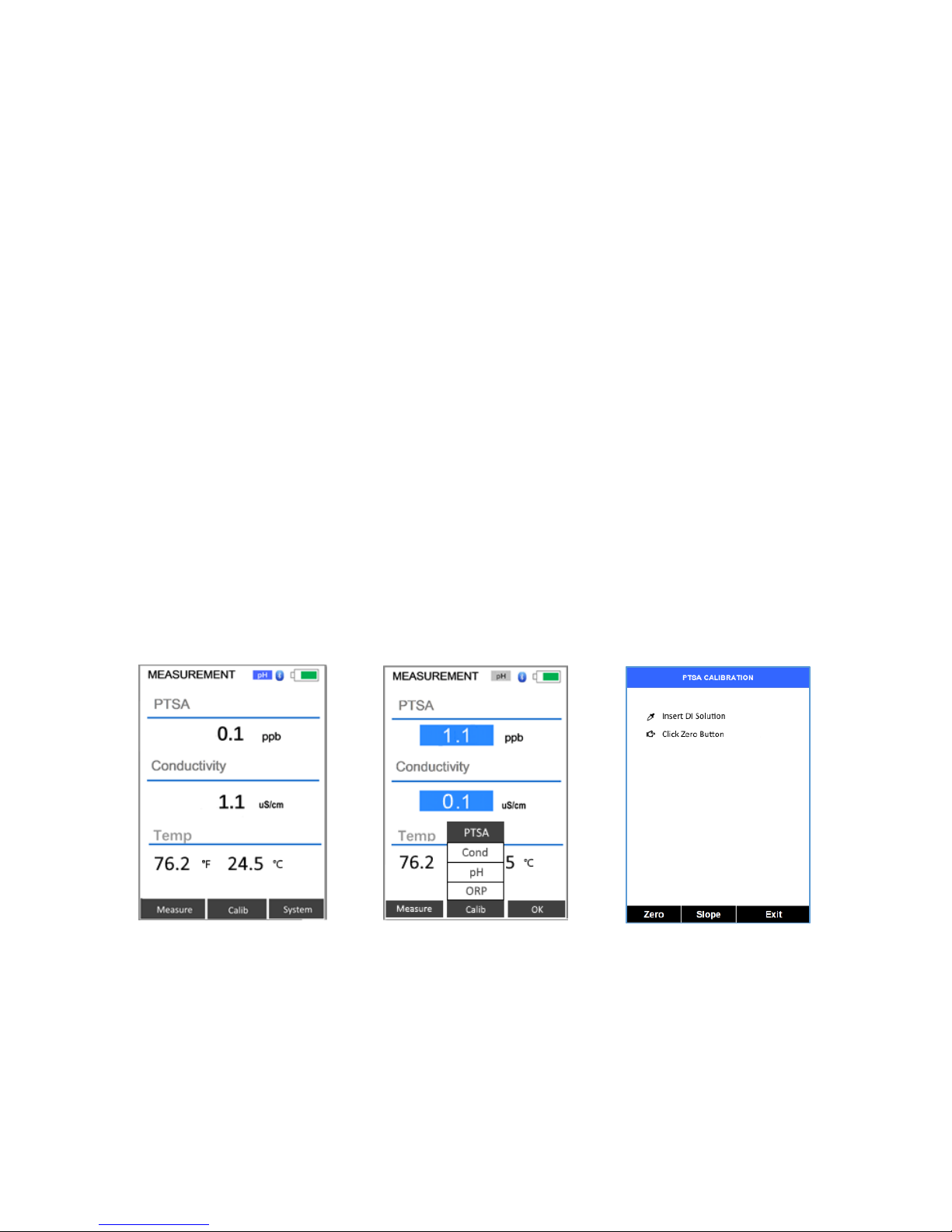
3. A screen like Figure 11 appears. The unit is actively reading and displaying both PTSA and
Conductivity.
4. Press Calib and then OK to select PTSA (alone) calibration, as shown in Figure 12
5. Press Zero to set the zero point, as shown in Figure 13.
6. After successful zero set, a checkmark symbol appears next to Click Zero Button to confirm
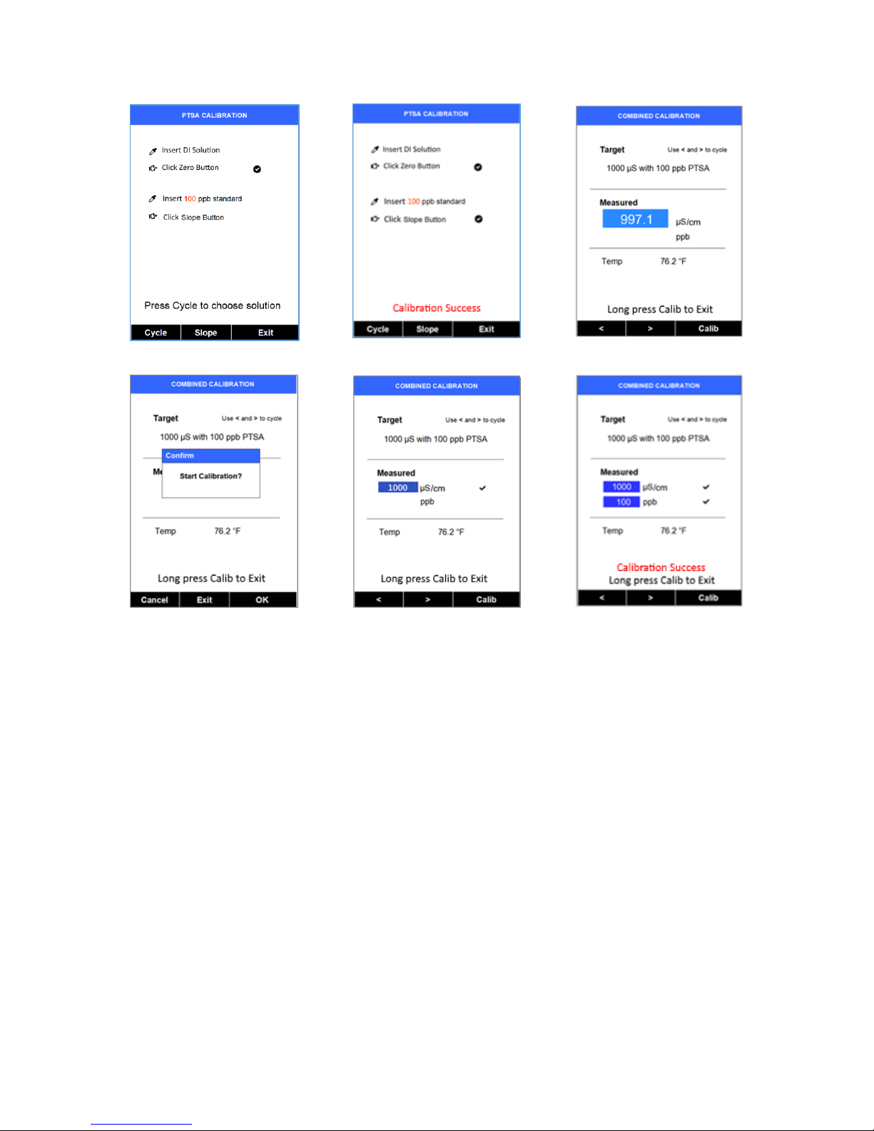
success. The screen also updates to show the Slope steps, as in Figure 14. The Cycle command
replaces the Zero command on the black bar, and the possible PTSA selection is displayed in
red. The default is 100 ppb:
7. Rinse the sample cell out at least twice with the desired PTSA standard, and with the
measurement cell near full.
8. If the 100 ppb PTSA default is not the desired PTSA for calibration, press the Cycle to cycle
among the PTSA standards 100-200-300 ppb. The value in red updates as the setting is being
changed.
9. Press Slope to set the slope of the standard desired and complete PTSA calibration. If
calibration is successful, the screen updates with a second checkmark for the Slope setting as
shown in Figure 15, and the message Calibration Succeed appears.
10. Press Exit to return to the measurement screen. Slight variance in the PTSA value is
acceptable. If you press Exit before the second checkmark appears, the calibration will not
be completed and must be re-done.
4.2 Combined Calibration Procedure
The combined 100 ppb PTSA and 1000 µS calibration requires the Pyxis PTSA-1010C combined
standard.
When Cond (conductivity) calibration is selected, the < or > keys can be used to cycle to different
conductivity calibration modes. With each press various elements of the display update, such as
the calibration title, the type (“Target”), and the black bar.
Page 17
Pyxis SP-710 Multimeter Operation Manual 17
1. Rinse sample cell with the Combined Standard and close the light shield.
2. Power on by pressing the OK key. Allow 5-10 seconds for meter to stabilize.
3. Press Calib (the > key) to launch the calibration selection screen (Figure 9). Press Calib again
to select Cond (conductivity) calibration. Press OK to start the calibration procedure. The
default conductivity calibration screen is the Combined Calibration (Figure 13). This will
calibrate both Conductivity (at 1000 µS) and PTSA (at 100 ppb) when using the Pyxis PTSA1010C combined standard.
4. Ensure the meter is filled with the Combined Standard and press Calib to confirm the
desired calibration. A confirmation popup appears as in Figure 17.
5. Press the OK key to execute both conductivity and PTSA calibrations (skip steps 6 and 7).
6. Or, press Cancel to return to the conductivity calibration type selection screen.
7. Or, press Exit to abandon calibration.
8. If Combined Calibration is successful, the measured field updates to the target conductivity
value (1000 µS), or very close. A checkmark shows. The screen appears as in Figure 18.
9. After about one second, if the PTSA calibration is successful, the PTSA value is also displayed
in the measured section below the conductivity value, and a checkmark appears. A small
variance is acceptable. The message “Calibration Succeed” appears in red, as in Figure 19.
10. After successful calibration, press and hold Calib for three seconds to return to the basic
measurement screen. Return is not automatic, except through a power-off cycle.
Figure 11. PTSA measurement
screen
Figure 12
Figure 13
Page 18
Pyxis SP-710 Multimeter Operation Manual 18
Figure 14
Figure 15
Figure 16
Figure 17
Figure 18
Figure 19
4.3 Standard Conductivity Calibration (500, 1000, 2500, or 5000 µS)
Example based on 1000 µS:
1. Rinse sample cell with the desired conductivity standard.
2. Power on by pressing the OK key. Allow 5–10 seconds for the meter to stabilize.
3. Press Calib (the > key) to launch the calibration selection screen (Figure 11). Press Calib again
to select Cond (conductivity) calibration. Press OK to start the calibration procedure. A screen
like Figure 16 appears. This is the default combined Calibration mode, which requires the Pyxis
combined standard.
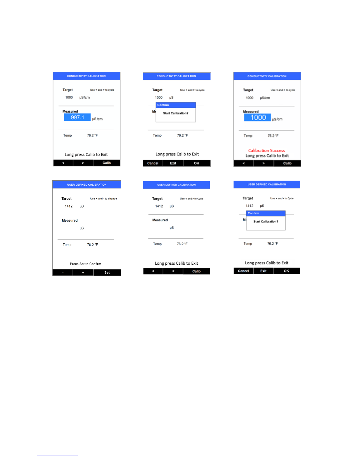
4. Use the > key to cycle to the desired calibration, for example, 1000 µS (Figure 20). The
Standard Conductivity selections are 500, 1000, 2500, and 5000 µS.
5. Press Calib to confirm the specific conductivity calibration desired. The screen updates as
shown in Figure 21.
Page 19

Pyxis SP-710 Multimeter Operation Manual 19
6. To start the calibration, press OK control key (skip steps 9 and 10).
7. Or, press Cancel to return to the Conductivity calibration selection screen (Figure 21). You can
change the conductivity calibration type by using the > or < control keys.
8. Or, press Exit to abandon calibration.
9. After successful conductivity calibration, the meter reads the sample and displays the value
in the measured section. A slight variance from the target is acceptable. A message displays
in red: “Calibration Succeed.” The meter display appears like Figure 22.
10. After successful calibration, press and hold Calib for three seconds, to return to the basic
measurement screen. Return to Read mode is not automatic, except through a power-off
cycle.
4.4 User-Defined Conductivity Calibration Procedure
1. Rinse sample cell with desired conductivity standard.
2. Power on by pressing the OK key. Allow 5-10 seconds for meter to stabilize.
3. Press Calib to launch the calibration selection screen (Figure 11). Press Calib again to select
Cond (conductivity) calibration. Press OK to start the calibration procedure. A screen like
Figure 16 appears. This is the default combined Calibration mode, which requires the Pyxis
combined standard.
4. Press the < key. A screen like Figure 23 appears.
5. If the displayed Target numeric value is not that the value you want, use the keys
labeled – and + (the < and > keys) to adjust the value as desired. Holding a key down scrolls
the values at a faster rate. Once the value is as desired, press Set to confirm the numeric
value to be used. The black bar updates as in Figure 24 (The label above the OK key now
changes to Calib from Set). Press Calib. The screen updates to Figure 25 with the confirmation
popup.
6. Press OK to execute the User Defined Conductivity calibration (skip steps 8 and 9).
7. Or, press Cancel to return to the User Defined Calibration (as in Figure 23), where the
desired User Defined calibration numeric value can be changed.
8. Or, press Exit to abandon calibration.
9. After successful User Defined calibration, the meter reads the sample value and displays the
value in the measured section. A message displays in red “Calibration Succeed.”
10. After successful calibration, press Calib for three seconds, to return to the basic measurement
screen. Return to Read mode is not automatic, except through a power-off cycle.
Page 20
Pyxis SP-710 Multimeter Operation Manual 20
If the user defined conductivity calibration mode is cycled to accidently, the < key and > key cannot
be used to cycle out this mode. Please press Set, and press and hold the OK key for three seconds
to exit this mode. Or abandon the user defined calibration step 8 above.
Figure 20
Figure 21
Figure 22
Figure 23
Figure 24
Figure 25
5 pH and ORP Calibrations
The commonly used pH 4.00, 7.00, and 10.00 buffer standards can be used to calibrate the SP-710
pH measurement.
Unlike the pH calibration, ORP calibration procedure and the calibration standards are not
standardized by the industry or government institutions. We recommend that you use Zobell’s ORP
standards (or Pyxis ORP-220) to calibrate the SP-710 and pay attention to the reference electrode
on which the ORP value is referenced. The reference information must be specified by the standard
supplier.
Page 21

Pyxis SP-710 Multimeter Operation Manual 21
5.1 pH Electrode Calibration
The SP-710 software is designed to provide a flexible calibration procedure. You can start with the
one-point pH 7 calibration and progressively add a second point and a third point calibration with
the pH 4 buffer and the pH 10 buffer. This allows you to choose a procedure based on the need of
measurement accuracy and the target pH range.
Starting the pH calibration: After the meter and the pH/ORP module are powered on, press
Measure (the < key) to switch to the pH measurement page. Press Calib (the > key) to start the pH
calibration procedure.
5.1.1 One-Point Calibration
Rinse the pH/ORP cell three times with the pH 7 buffer and fill the cell with the pH 7 buffer.
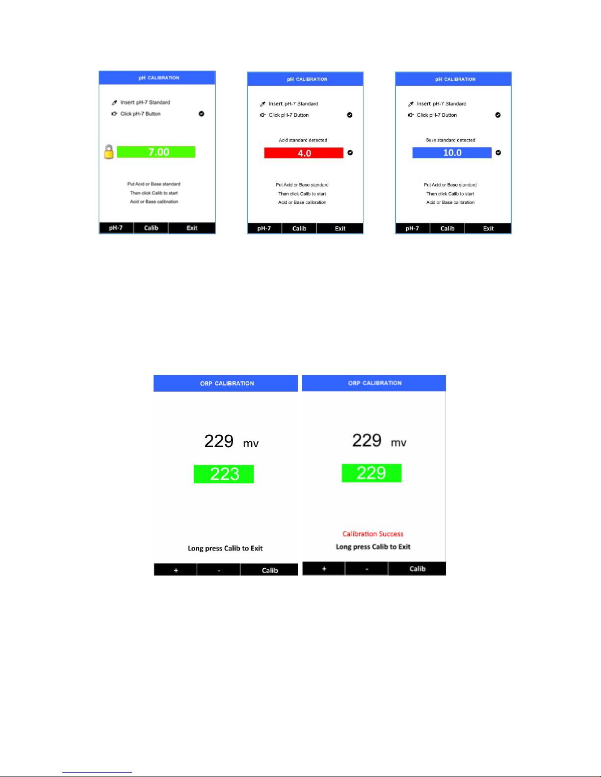
Press pH-7 (the < key) to start one-point calibration. A checkmark after Click pH-7 is displayed if
the calibration succeeds (Figure 26). Otherwise a warning message is displayed.
5.1.2 Second-Point Calibration
When the one-point pH 7 calibration is complete, press Exit to exit, or continue to the pH 4 or pH
10 calibration. If a second buffer is added into the cell, the SP-710 automatically determines the
buffer pH and displays the determined buffer pH value for confirmation.
If you choose the pH 4 buffer to do the second-point calibration, the pH 4 buffer is identified and
the value 4.00 is shown. Press Calib to complete the pH 4 calibration. A checkmark after Click
pH-4 is displayed if the calibration succeeds (Figure 27). Otherwise a warning message is
displayed.
Alternatively, you can use the pH 10 buffer for the second-point calibration.
5.1.3 Third-Point Calibration
When the second-point calibration is complete, press Exit to exit, or continue to a third-point
calibration. If you have used the pH 4 buffer in the second-point calibration, you must use the pH
10 buffer for the third-point calibration.
Rinse the pH/ORP cell three times and fill the cell with the pH 10 buffer. The pH 10 buffer is
automatically identified. Press Calib to complete the third-point calibration. A checkmark after
Click pH-10 is displayed if the calibration succeeds (Figure 28). Otherwise a warning message is
displayed. Press Exit to finish the final calibration process.
Page 22
Pyxis SP-710 Multimeter Operation Manual 22
Figure 26
Figure 27
Figure 28
5.2 ORP Calibration
Launch the pH/ORP measurement page. Press Calib to launch the pH/ORP calibration selection
dropdown. Press Calib again to move the selection to ORP. Press OK to start ORP calibration.
Press + or – to select an ORP value to match your ORP standard. Press Calib to complete the
calibration.
Figure 29
The ORP scale of the SP-710 depends on the ORP scale of the calibration standard. For example,
if the value of 220 mV for the common Zobell’s standard at 25 oC is entered in the above
calibration, the ORP value reported by the SP-710 after calibration is referenced to the
Ag/AgCl(3M KCl) scale. This is because the value of 220 mV is based on the Ag/AgCl(3M KCl)
reference electrode. If the value entered in the above calibration is 429 mV, the ORP value
reported by the SP-710 is referenced to the SHE, because the value of 429 mV at 25 oC for the
Zobell’s standard is SHE based.
Page 23

Pyxis SP-710 Multimeter Operation Manual 23
The value in the following table can be used to convert the Ag/AgCl reference electrode based
ORP value to the SHE-based ORP value. To obtain the SHE-based ORP value, add the number in
the table to the corresponding Ag/AgCl reference electrode-based value. To use the table, the
temperature of the standard solution measured by the SP-710 must be used.
Temperature
Ag/AgCl
(1M KCl)
Ag/AgCl
(3M KCl)
Ag/AgCl
(saturation KCl)
68 oF (20 oC)
+234
+213
+202
77 oF (25 oC)
+231
+209
+199
86 oF (30 oC)
+228
+205
+196
6 Chlorine Calibration
Press Measure (the > key) to launch measurement selection dropdown menu. Press Measure
again to move the selection to COLOR. Press OK to start the chlorine page.
6.1 Chlorine Reagent Blank (Zero) Calibration
1. Fill the sample cell with DI water
2. Click Zero (the < key)
3. Draw out DI water from the sample cell into the reagent pipette, shake the pipette to fully dissolve
the reagent before squeezing the water sample in the pipette back to the sample cell
4. Click Timer, the SP-710 will start the 2-minute timer.
5. The SP-710 will continuously display the free chlorine concentration, please click Stop to stop
measurement if the real-time readings remains steady or wait for the 2-minute timer to time out.
6. Click Cal to launch chlorine calibration page
7. Click Blank to start blank calibration.
8. “Blank calibration succeeds” will be displayed if blank calibration completed (Figure 30).
9. Long press Default to return to chlorine page.
Page 24

Pyxis SP-710 Multimeter Operation Manual 24
Figure 30
Figure 31
6.2 Chlorine Slope Calibration
1. Fill the sample cell with a known free chlorine standard solution.
2. Click Zero (the < key).
3. Draw the standard solution from sample cell into the reagent pipette, shake the bottle to fully
dissolve the reagent before squeezing the reacted sample back into the sample cell.
4. Click Timer, on the SP-710 to start the 2-minute timer.
5. The SP-710 will continuously display the free chlorine concentration, please click Stop to stop the
measurement if the real-time reading remains steady or wait for 2-minute timer to complete.
6. Click Cal to launch chlorine calibration page.
7. Click Slope to launch slope calibration.
8. Click + button (<) or – button (>) to adjust free chlorine solution concentration to the target value
of the standard used in this procedure
9. Click Calib to complete slope calibration.
10. “Slope calibration succeeds” will be displayed if slope calibration completed (Figure 31).
11. Long press Calib to return to chlorine page.
Note: Free Chlorine Calibration Standard Solution concentration should be within 1.1 to 2.2 ppm for proper
calibration.
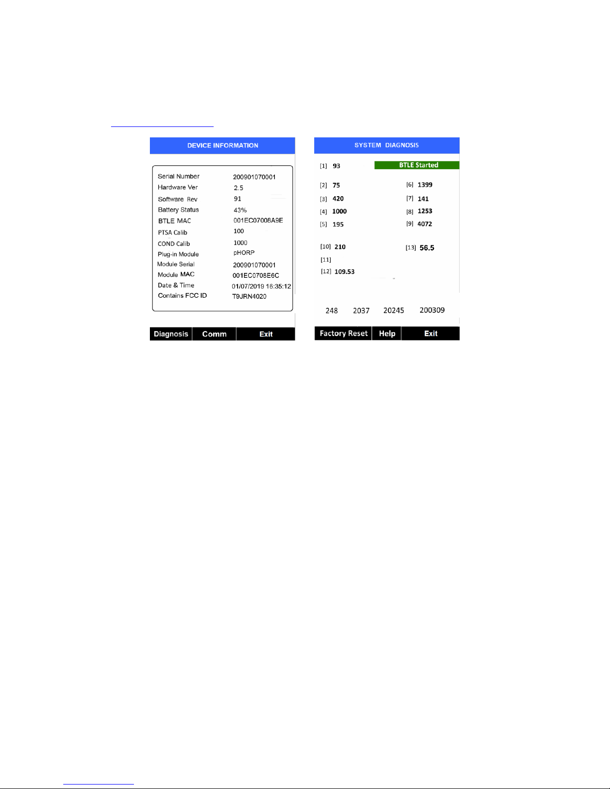
7 Device Information and Diagnosis
Device information is shown when the key labeled System in any Measurement mode is pressed
momentarily (Figure 3). The screen contains the device serial number, software version, and
hardware version (Figure 32). The battery life as a percentage and the standard that was used in
the last calibration are also shown.
Page 25
Pyxis SP-710 Multimeter Operation Manual 25
Press the key labeled Diagnosis to switch to the Diagnosis screen where raw measurement data
are displayed (Figure 33). (The information has no use for normal operation.) Provide an image
of both the device information screen and the diagnosis screen when you contact Pyxis
([email protected]) for troubleshooting your device or call 1-866-203-8397.
Figure 32 Figure 33
8 Device Maintenance
The working life of the SP-710 is greatly increased if you follow these maintenance best
practices:
• Rinse the meter with tap water or DI water after measurement, and remove residual water
using a paper towel.
• Close the pH/ORP seal firmly to keep the pH and ORP cell wet.
• Add the pH storage solution to the pH/ORP cell at all times when the meter is not being
used.
• Use a Q-tip to gently clean the inside of the fluorescence and conductivity cell to remove
any deposits that may have attached to the optical and electrode surfaces.
• On a monthly basis or as needed we recommend conducting a chemical cleaning using Pyxis
SER-02 Handheld Cleaning Solution of the fluorescence and conductivity cell to remove
deposition or film development.
• Completely wet the fluorescence and conductivity cell for an hour before a measurement if
the meter has not been used in more than two weeks.
• Do not expose the SP-710 to an extreme high or low temperature condition such as leaving
the meter inside an unattended automobile. The pH electrode can survive a few short period
exposures to -18 oC (0 oF) or 60 oC (140 oF). Repeated extreme low and high temperature
cycling can damage the pH electrode.
Page 26
Pyxis SP-710 Multimeter Operation Manual 26
9 Replacing the pH/ORP module (Part #50313)
9.1 Module Replacement
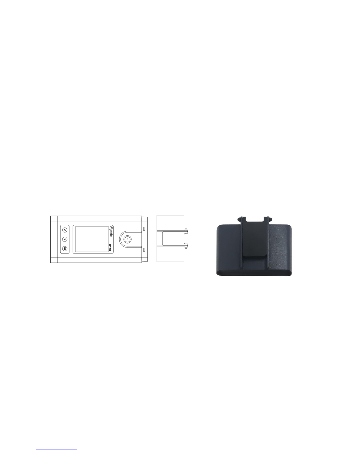
The pH/ORP module in the SP-710 can be replaced when the original module reaches the end of
its working life. Pyxis offers a 6-month warranty on the pH/ORP module. Pyxis recommends
replacing the module at a frequency of every 9-12 months as a best practice.
If the module is turned on for 20 minutes a day, the module battery can last for about a year. The
module indicator light will flash red if the module battery is low.
Order a replacement module from Pyxis, asking for options with modules that the battery can be
replaced. Follow the instructions below to install the replacement module:
1. Turn off the meter.
2. Ensure that there is no water in the two measurement cells.
3. Detach the spent pH/ORP module by pulling the module away from the main module
4. Attach a new pH/ORP module to the main module as shown in Figure 36
Figure 34. pH/ORP module (Part #51303) replacement
Page 27

Pyxis SP-710 Multimeter Operation Manual 27
9.2 Bluetooth Pairing Your pH/ORP Module to SP-710
1. Turn on the main module.
2. Press System (the > key) to launch the device information screen as shown in Figure 32.
3. Press Comm (the > key) to launch the communication screen (Figure 35).
4. Turn on the pH/ORP module by lowering the seal to touch the front face of the module. The
module indicator light will flash green.
5. Press Scan (the < key) on the main module. The information of the discovered module will be
listed as shown in Figure 36.
6. Press Pair (the > key) to pair the pH/ORP module to the main module. If pairing is successful,
message “Pair Success!” will be shown the top of the screen as shown in Figure 37.
Figure 35
Figure 36
Figure 37
10 Bluetooth Connection of SP-710 to Devices
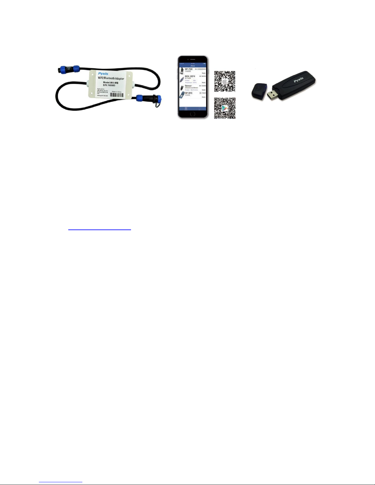
The Pyxis SP-710 can be connected to a smart phone or a computer via the built-in Bluetooth Low
Energy Connection (BTLE). The uPyxis© app for smartphone is available for free download to both
Apple and Samsung devices per QR codes below.
A laptop with uPyxis© app can use the Bluetooth Adapter (MA-NEB) included with the SP-710 as a
standard accessory to connect to the SP-710 for parameter configuration, firmware upgrade, and
other tasks. The Pyxis uPyxis software can be downloaded from www.pyxis-lab.com/support.html
Page 28
Pyxis SP-710 Multimeter Operation Manual 28
Figure 38. Pyxis Inline Bluetooth Adapter
(MA-WB)
uPyxis© App
Bluetooth Adapter For PC
(MA-NEB)
The SP-710 can scan, discover, and calibrate a nearby Pyxis inline probe with the Pyxis Inline
Bluetooth Adapter (MA-WB) connected between the Pyxis inline probe & controller (see next
section).
The SP-710 can be paired with other Pyxis devices for exchanging data over Bluetooth. In the
normal operation modes, the Bluetooth function is turned off. To turn on the Bluetooth wireless
function, press System, and then press Comm.
Other SP-710 wireless functions are available. For more information, contact Pyxis Lab
([email protected]) or call at 1-866-203-8397.
11 Calibrate ST-500 with SP-710
The SP-710 can be used to verify the result of inline Pyxis ST-500 and other probes by measuring
the sample water taken from the inline probe sample line. The SP-710 can then be used to calibrate
the inline probes over the Bluetooth connection.
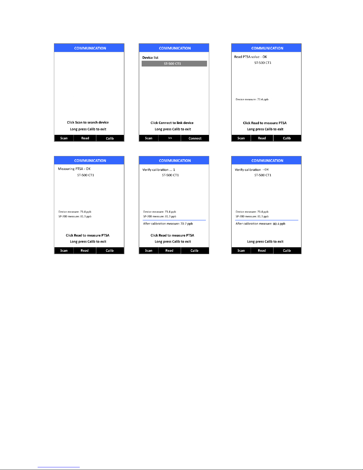
Press System and then Comm to enter the communication module. The following interface appears
on the screen.
Press Scan. A list of accessible ST-500s is displayed. Use the >> key to select the one to be
calibrated. Press Connect to connect the SP-710 to the selected ST-500.
When the connection is established, the SP-710 reads the latest reading from the connected ST500 and displays the reading as shown in Figure 41.
Use the SP-710 meter to measure the sample water by pressing Read. The PTSA value is displayed
on the screen below the ST-500 readings, as shown in Figure 41. Press Calib to send the
calibration instruction to the ST-500 via Bluetooth connection.
Page 29
Pyxis SP-710 Multimeter Operation Manual 29
Figure 39
Figure 40
Figure 41
Figure 42
Figure 43
Figure 44
After that, the connected ST-500 is calibrated to the value measured by the SP-710. The SP-710
reads the ST-500 three times to verify that the calibration is successful. Note that it takes about
one minute for the ST-500 to approach the calibrated reading, and the three verifying readings may
not be exactly the same as the value measured by the SP-710 (as demonstrated in Figure 44). Press
Read again to take more readings from the ST-500 if necessary.
Page 30

Pyxis SP-710 Multimeter Operation Manual 30
12 REGULATORY APPROVAL
United States
The SP-710 sensor has been tested and found to comply with the limits for a Class B digital device,
pursuant to part 15 of the FCC Rules. These limits are designed to provide reasonable protection
against harmful interference in a residential installation. This equipment generates, uses and can
radiate radio frequency energy, and if not installed and used in accordance with the instructions,
may cause harmful interference to radio communications. However, there is no guarantee that
interference will not occur in an installation. If this equipment does cause harmful interference to
radio or television reception, which can be determined by turning the equipment off and on, the
user is encouraged to try to correct the interference by one or more of the following measures:
• Reorient or relocate the receiving antenna.
• Increase the separation between the equipment and receiver.
• Connect the equipment into an outlet on a circuit different from that to which the receiver is
connected.
• Consult the dealer or an experienced radio/TV technician for help
Canada
This device complies with Industry Canada license exempt RSS standard(s). Operation is subject to
the following two conditions: (1) this device may not cause interference, and (2) this device must
accept any interference, including interference that may cause undesired operation of the device.
Le présent appareil est conforme aux CNR d'Industrie Canada applicables aux appareils radio
exempts de licence. L'exploitation est autorisée aux deux conditions suivantes: (1) l'appareil ne doit
pas produire de brouillage, et (2) l'utilisateur de l'appareil doit accepter tout brouillage
radioélectrique subi, même si le brouillage est susceptible
Contact us
Contact us if you have questions about the use or maintenance of the SP-710 Water Multimeter:
Pyxis Lab, Inc.
1729 Majestic Dr. Suite 5
Lafayette, CO 80026 USA
1-866-203-8397
www.pyxis-lab.com
[email protected]
Page 31
Pyxis SP-710 Multimeter Operation Manual 31
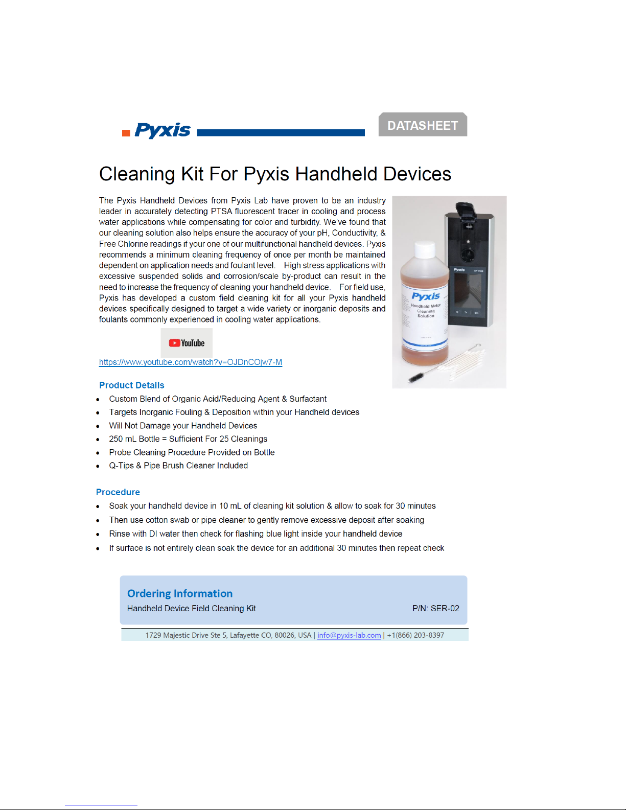
13 Appendix. Cleaning Kit
 Loading...