

Page 1

M
0
524
AESF"CJriCJEA
0
E
L...E:
L
..
.
Page 2
Congratulations
Congratulations on the purchase of your state-of-the-art remote start
and security system. Reading this Owner’s Guide prior to using your
system will help maximize the use of your system and its many features.
Please visit: www.pythoncarsecurity.com – For general and additional
guide information. For any additional questions please contact your
authorized Directed dealer or contact Directed at 1-800-753-0600.
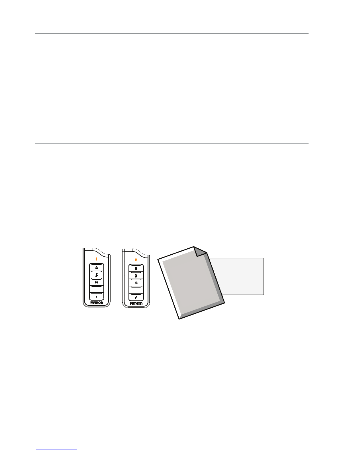
What you get
Welcome to the best generation of security with remote start. Your
system contains everything you need.
s Responder LE remote control
s 1-way Companion remote control
s Owner’s guide and Warranty card
Owner’s
Guide
AUX
AUX
Warranty
Card
Page 3

Important information
Government Regulations and Safety information
Read the Government Regulations and Warning! Safety
First sections of this manual prior to operating this system.
Warning! Failure to heed this information can result in
death, personal injury or property damage and may also
result in the illegal use of the system beyond its intended
purpose.
Your Warranty
Your Responder LE system comes with a warranty. Please make sure
you receive the warranty registration card and proof of purchase from
your dealer indicating the product was installed by an authorized
Directed dealer. Please validate it online at www.prodregister.com/
directed or complete and return the warranty registration card.
Replacement remote controls
If additional remote controls are desired, please see your authorized
dealer or visit us at www.directedstore.com to order. Part numbers
are: 7251P for Responder LE 2-way remote control and 7152P for
the companion remote control.
Page 4

Contents
Getting Started .................................................................................................... 4
Keys to using this manual ...................................................................... 4
Responder LE 2-Way ........................................................................................... 5
Using your System ............................................................................................... 7
Commands and Confirmations .............................................................. 7
Performing Commands ......................................................................... 7
Remote Control Command table ............................................................ 8
Fault Condition Alerts ........................................................................... 8
Basic Commands (Direct Access) ........................................................................ 10
Arm ................................................................................................. 10
Disarm ............................................................................................. 10
Remote Start ...................................................................................... 11
AUX/Trunk ........................................................................................ 11
Advanced Commands: (Level 1) ......................................................................... 12
Silent Arm ......................................................................................... 12
Runtime Reset .................................................................................... 12
AUX 1 .............................................................................................. 13
Temperature Request .......................................................................... 13
Advanced Commands: (Level 2) ......................................................................... 14
Sensor Bypass ................................................................................... 14
Remote Valet .................................................................................... 14
Timer Start* ...................................................................................... 15
AUX 2 .............................................................................................. 15
Arm Status ........................................................................................ 15
Advanced Commands: (Level 3) ......................................................................... 16
Sensor Silent Arm* ............................................................................ 16
Smart Start** .................................................................................... 16
AUX 3 .............................................................................................. 17
Runtime Remaining ............................................................................ 17
Advanced Commands: (Level 4) ......................................................................... 18
Full Silent Arm* ................................................................................. 18
Defogger** ...................................................................................... 18
AUX 4 .............................................................................................. 18
Remote Control Configuration ............................................................................ 19
Remote Programming ......................................................................... 19
Remote Pairing ................................................................................. 19
Remote Features ............................................................................... 20
Car 2 ............................................................................................... 22
Remote Beep ..................................................................................... 22
Sensor Adjust .................................................................................... 23
Page 5

Alarm Features .................................................................................................24
Normal Arm Protection ....................................................................... 24
Sensor Silent Arm protection ............................................................... 24
Full Silent Arm Protection .................................................................... 25
Sensor Warn-away ........................................................................... 25
Full Trigger ........................................................................................ 25
Emergency Override .......................................................................... 25
Trigger Zone Fault Report.................................................................... 26
Alarm Report ..................................................................................... 26
Nuisance Prevention (NPC) ................................................................. 27
Remote Start Features ........................................................................................ 28
Pit Stop Mode ................................................................................... 28
Key Takeover..................................................................................... 28
Remote Start Safe-lock ........................................................................ 29
Disabling Remote Start ....................................................................... 29
Advanced Start ................................................................................. 29
Temperature Reporting ........................................................................ 30
Remote Start Time-out Alert .................................................................. 31
Manual Transmission Start (MTS mode) ................................................ 31
Turbo Timer Mode .............................................................................. 32
Remote Start Faults ............................................................................. 32
Remote and System Operations .......................................................................... 34
Passive Arming* ................................................................................ 34
Auto Re-arming* ................................................................................ 34
Onetime Bypass* .............................................................................. 34
Valet Mode ....................................................................................... 35
Power Save ....................................................................................... 35
Rapid Resume ................................................................................... 35
Automatic Remote Updates ................................................................. 35
Out of Range .................................................................................... 36
No Remote Output ............................................................................. 36
Feature not Available ......................................................................... 36
Car Select ......................................................................................... 37
System Expansion Options ................................................................................. 38
Battery Information ............................................................................................ 40
Low Battery ....................................................................................... 40
Battery Life ........................................................................................ 40
Battery Disposal ................................................................................ 41
Glossary of Terms .............................................................................................. 42
Patent Information ............................................................................................. 43
Government Regulations .................................................................................... 44
Page 6

Warning! Safety First ......................................................................................... 46
Installation ........................................................................................ 46
Remote Start Capable ........................................................................ 46
Manual Transmission Vehicles ............................................................. 46
Interference ....................................................................................... 48
Upgrades ......................................................................................... 48
Water/Heat Resistance ...................................................................... 48
Limited lifetime consumer warranty ..................................................................... 49
Page 7

Getting Started
Keys to using this manual
Specific actions (in bold type) and style conventions are used consistently throughout this manual, they are as follows:
s Press: implies pushing in and releasing a button.
s Hold: is used after Press actions when a button needs to be held
in position for an extended period of time, typically several seconds.
s Italicized words denote section/sub headings in this guide and
can be located through the table of contents.
s An asterisk (*) when used after a word or phrase denotes that
additional details can be found in related sections usually noted
at the bottom of the page or end of the section.
s Ghost LED’s are identified by the command/function button they
are associated with.
4
© 2011 Directed Electronics. All rights reserved.
Page 8
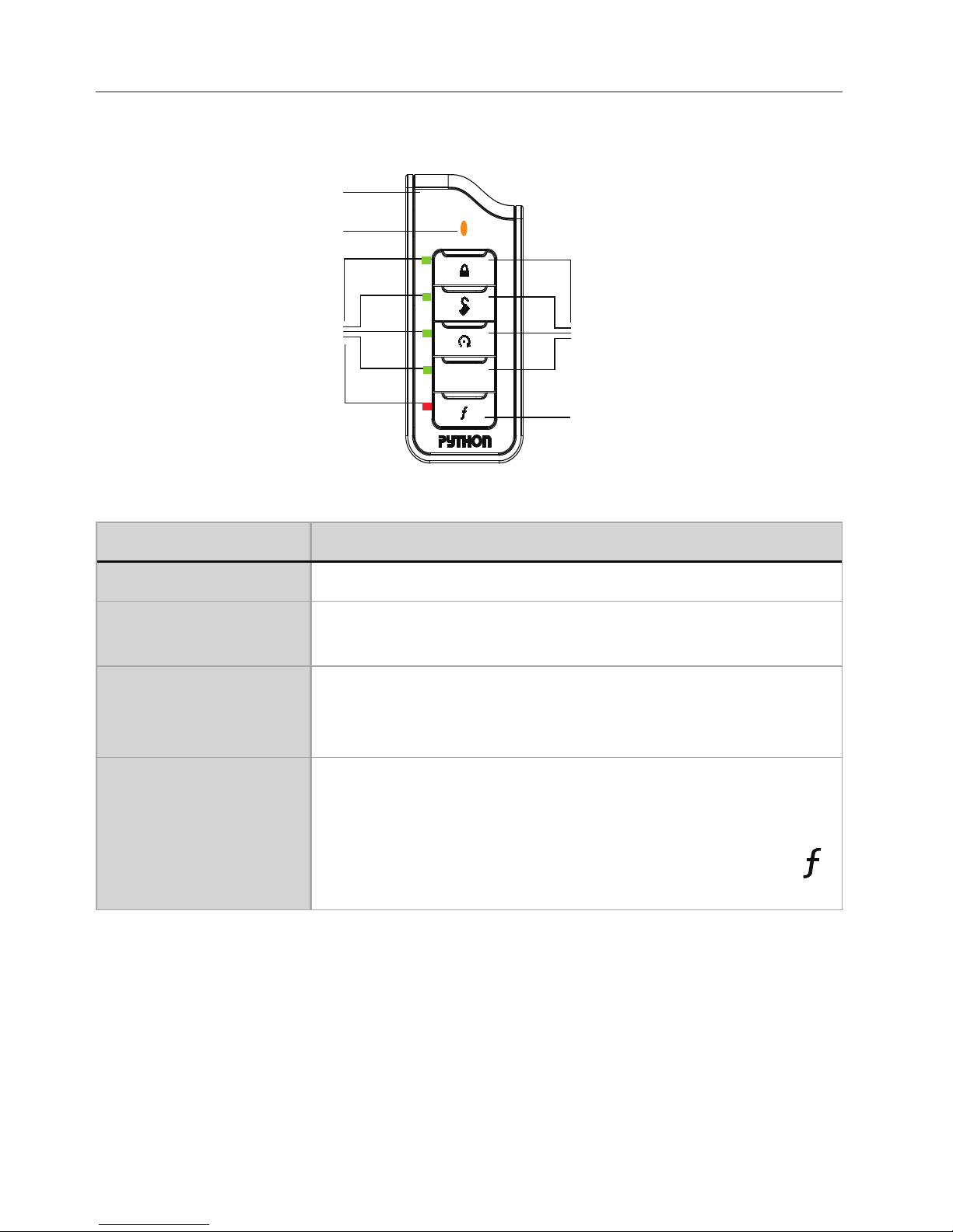
Responder LE 2-Way
Internal
Antenna
Transmit
LED
Ghost
LED’s
AUX
Feature Description
Internal Antenna Used for transmitting and receiving* information
Command buttons (4) Used to perform arming, disarming, auxiliary channel and
remote start commands
Function button Used to access function levels for commands, configura-
tion menus for programming, Car Selection, and to request
reports.
Command
Buttons
Function
Button
Ghost LED’s ** Each button has an associated LED next to it that are active
* 2-way communication is only applicable to the Responder LE
remote control
** Term denotes that these LED’s are only visible when On (Ghost
LED’s are only applicable to the Responder LE remote control).
© 2011 Directed Electronics. All rights reserved.
during related operations. These LED’s are labeled respectively as:
Arm LED, Disarm LED, Remote Start LED, Aux LED, and
LED
5
Page 9

Control Center
Control button
Status LED
The Control Center, typically located on the upper part of the front
windshield sends and receives commands or messages to and from
your system. It consists of:
s The In-vehicle system antenna, for 2 way communication.
s The Status LED, as a visual indicator of the system’s status.
s The Control button, for placing the system into Valet Mode* and
to perform the Emergency Override** operation.
* See Remote and System Operations section for details.
** See
6
Alarm Features for details.
© 2011 Directed Electronics. All rights reserved.
Page 10

Using your System
Commands and Confirmations
Commands, Basic or Advanced, are used to activate system features
and are performed by pressing one of the Command buttons. Basic
commands control the most often used security and remote start features while Advanced commands control more specialized features
and request reports.
Confirmations for Basic or Advanced commands are indicated
first by siren chirps and parking light flashes, and then by illuminated
Ghost LED’s and beeps or tones on the remote control. A description
of each feature confirmation is found in the following Basic command
and Advanced command sections.
Performing Commands
Perform Basic commands by pressing a Command button (Ghost LED’s
are off).
Perform Advanced Commands by first accessing Levels 1-4 using the
button and then by pressing a Command button while within a
Level (Levels are indicated by illuminated ghost LED’s after pressing
button).
Advanced command example: Silent Arm
1. Press the
LED turns on.
2. Press the
Silent Arm command.
button once to access Function Level 1, the
button while the LED is still on to perform the
3. The Arm LED will illuminate to confirm when the Silent Arm message from the system is received.
© 2011 Directed Electronics. All rights reserved.
7
Page 11
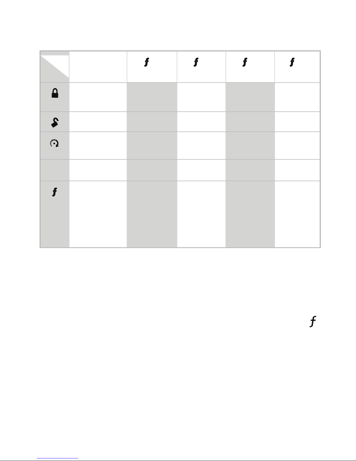
Remote Control Command table
Level
Button
AUX
Direct Access
Arm/Lock
(Panic)
Disarm/Unlock Silent Disarm Remote Valet Car Finder
Remote Start Runtime
Aux/Trunk AUX 1 AUX 2 AUX 3 AUX 4
Advance Level,
Change Car
(3 sec), Enter
Silent Arm Sensor
Reset
Temperature
Check*
x 1
LEVEL 1
x 2
LEVEL 2
Sensor Silent
Bypass
Timer Start Smart Start Defogger
Arm Status* Runtime
Arm
Remaining*
x 3
LEVEL 3
LEVEL 4
Full Silent
Arm
x 4
programming
(8 sec)
*Not available for 1-way companion remote control
Fault Condition Alerts
If, when performing a command, a condition exists that does not allow activation of an Alarm feature* or Remote Start feature**, the
LED and a fault tone plays to alert of the fault condition.
* Alarm feature not available when the system status is incorrect
upon receiving the command. (Example: Sensor bypass command is received when disarmed).
Refer to the notes included in the following command descriptions
that address these faults or go to Feature not Available under the
Remote and System Operations section for more details.
8
© 2011 Directed Electronics. All rights reserved.
Page 12

** Remote Start feature not available when the Remote Start status is
incorrect upon receiving the command. (Example: Runtime reset
command received when remote start is off).
Refer to the notes included in the command descriptions that address these faults or go to Remote Start Faults under the Remote
Start Features section for more details.
© 2011 Directed Electronics. All rights reserved.
9
Page 13

Basic Commands (Direct Access)
No Ghost LED’s on
Arm
Press and release
The alarm arms, doors lock (if connected), and the siren chirps and
parking lights flash once. The Arm LED and beeps play to confirm. If
Valet mode* is On, the doors lock and the Arm LED,
fault tone plays. Exit Valet mode to arm the alarm normally.
If a trigger zone fault is detected the siren chirps once again and the
remote will emit a Trigger Zone Fault Report**, the Arm LED,
and a fault tone plays.
To Arm and Panic
Press and hold
The alarm Arms (or Locks in Valet) and, after 2 seconds, sounds
the siren and flashes the parking lights. The ghost LED’s flash and
siren tones play to confirm. Press the
output.
or button to stop the
LED and a
LED
Disarm
Press and release
The alarm disarms, doors unlock (if connected), and the siren chirps
and parking lights flash twice. The Disarm LED and beeps play to
confirm. If Valet mode* is On, the doors unlock and the Disarm LED,
LED and fault tones play.
An Alarm Report** will replace the disarm output if the alarm was
10
© 2011 Directed Electronics. All rights reserved.
Page 14

triggered; the siren will chirp 4 or 5 times, and the Disarm LED,
LED and 4 or 5 fault tones play to alert of the report.
Remote Start
Press and release
Activates (or if On, deactivates) the remote starter. The engine and
parking lights turn On and the Remote start LED and On tones play,
or the engine and parking lights turn Off and the Remote start LED
and Off tones play to confirm. If a Remote start configuration issue
prevents the engine from starting, the
LED and a fault tone will play
while the parking lights flash a Remote Start fault report*** to identify
the fault.
AUX/Trunk
Press and hold AUX
The Trunk opens (if connected) when this button is pressed for 2 seconds. The Aux LED and tones play to confirm.
* See Remote and System Operations for details.
** See
*** See
For Manual transmission vehicles see
Alarm Features for details.
Remote Start Faults (under Remote Start Features) for details.
Remote Start Features
© 2011 Directed Electronics. All rights reserved.
Manual Transmission Start in the
section for more details.
11
Page 15

Advanced Commands: (Level 1)
Press and release the button 1 time. The LED illuminates indicat-
ing Level 1
Silent Arm
Press and release
The alarm arms, doors lock (if connected), and the parking lights flash
once. The Arm LED turns on to confirm. Valet mode* or Trigger Zone
Fault Report** messages may be received.
Silent Disarm
Press and release
The alarm disarms, doors unlock (if connected), and the parking lights
flash twice. The Disarm LED turns on to confirm. The Silent Disarm
output may be replaced by the Alarm Report**
Runtime Reset
Press and release
If more time is needed while remote start is active, runtime reset will
reset the runtime counter to the pre-programmed setting. The green
ghost LED’s show the runtime and the Remote start On tones play to
confirm runtime reset.
Note
12
Remote Start must be On to use this feature.
© 2011 Directed Electronics. All rights reserved.
Page 16

AUX 1
Press and release AUX
Activates (or if On, deactivates) the Aux 1 output. The Aux LED and
On tones or Off tones play to confirm.
Temperature Request
Press and hold the button
Requests the vehicle’s interior temperature and displays it by illuminating the green ghost LED’s; cold is 1 LED, cool (2), warm (3), warmer
(4)
.
* See Remote and System Operations section for details.
** See
© 2011 Directed Electronics. All rights reserved.
Alarm Features for details.
13
Page 17

Advanced Commands: (Level 2)
Press and release the button 2 times. The and Aux LED’s illumi-
nate indicating Level 2
Sensor Bypass
Press and release
Performing the Sensor Bypass command will incrementally bypass sensor operations and be confirmed as follows:
s Warn-away bypass: The Parking lights flash 2 times. The Arm
LED, 1 beep and 1 fault tone play to confirm. Sensors will be
activated for Full Trigger levels of impact only.
s Warn-away & Full trigger bypass: The Parking lights flash 3
times. The Arm LED, 1 beep and 2 fault tones play to confirm.
Sensors will not be activated for any level of impact.
s Sensor Bypass off: The Parking lights flash 1 time. The Arm LED
and 1 beep play to confirm. Sensors are fully operational.
.
Note
System needs to be armed to perform Sensor Bypass.
Perform arm command any time to turn Sensor Bypass Off.
Remote Valet
Press and release
Enters (or if On, exits) Valet Mode. The Control Center LED turns on
and off accordingly. The Disarm LED and Valet beeps play (1 for on,
2 for off) to confirm.
14
© 2011 Directed Electronics. All rights reserved.
Page 18

Timer Start*
Press and release
Activates (or if On, deactivates) Timer Start. The parking lights flash
quickly four times for On and slowly four times for Off. The Remote
Start LED and beeps play (1 for on, 2 for off) to confirm..
Note
System needs to be armed or Timer Start will not start the
engine.
AUX 2
Press and release AUX
Activates (or if On, deactivates) the Aux 2 output. The Aux LED and
On tones or Off tones play to confirm.
Arm Status
Press and hold the button
The remote will generate an output using the LED’s and beeps/tones
to display the systems Arm Status since its last update message or command operation. It will report status via ghost LED’s, beeps, and tones
as described in this section for Arm, Disarm, Valet mode arm, Valet
mode disarm, Sensor Silent arm, Full Silent arm.
* See Advance Start under Remote Start Features for details.
© 2011 Directed Electronics. All rights reserved.
15
Page 19
Advanced Commands: (Level 3)
Press and release the button 3 times. The , Aux and Remote
Start LED’s illuminate indicating Level 3
Sensor Silent Arm*
Press and release
The alarm arms, doors lock, and the siren chirps and parking lights
flash 3 times. The Arm LED, 1 beep and 3 fault tones play to confirm.
Car finder
Press and release
The siren emits one long chirp and the parking lights flash for 10 seconds. The Disarm LED and 1 beep play to confirm. The parking light
flashes stop if armed or disarmed while Car Finder is in progress.
Smart Start**
Press and release
Activates (or if On, deactivates) Smart Start. The parking lights flash
quickly five times for On and slowly five times for Off. The Remote
Start LED and beeps play (1 for on, 2 for off) to confirm.
Note
16
System needs to be armed or Smart Start will not start the
engine.
© 2011 Directed Electronics. All rights reserved.
Page 20

AUX 3
Press and release AUX
Activates (or if On, deactivates) the Aux 3 output. The Aux LED and
On tones or Off tones play to confirm.
Runtime Remaining
Press and hold the button
Requests the remaining Remote start runtime and temporarily displays
it in 4 increments using the green Ghost LED’s.
Example for 12 minute runtime:
s 3 LED’s: 6 to 9 minutes remaining (50 - 75% of time selected).
s 1 LED: less than 3 minutes remaining (<25% of time selected).
Note
Remote Start must be On to use this feature.
* See Alarm Features for more details.
** See
© 2011 Directed Electronics. All rights reserved.
Advance Start under Remote Start Features for details.
17
Page 21

Advanced Commands: (Level 4)
Press and release the button 4 times. The , Aux, Remote Start
and Disarm LED’s illuminate indicating Level 4
Full Silent Arm*
Press and release
The alarm arms, doors lock, and the siren chirps and parking lights
flash 4 times. The Arm LED, 1 beep and 4 fault tones play to confirm.
Defogger**
Press and release
Activates the vehicle Defogger circuit (if connected) while Remote Start
is activated and the parking lights flash 3 times. The Remote start LED
and 1 beep play to confirm. For convenience, the Defogger circuit
will also automatically activate 10 seconds after remote starting if the
temperature is below 55°F.
Note
Remote Start must be active to use this feature.
AUX 4
Press and release AUX
Activates (or if On, deactivates) the Aux 4 output. The Aux LED and
On tones or Off tones play to confirm.
* See Alarm Features for more details.
** This feature must be installed and turned on by an authorized Directed
dealer.
18
© 2011 Directed Electronics. All rights reserved.
Page 22

Remote Control Configuration
Remote Programming
The Responder LE and 1-way companion remote controls have operations that can be configured to a user’s personal preferences. The following instruction will direct you through the available programming
options for both remotes.
Enter programming, press and hold the
remote emits one long beep and the transmit LED turns on to indicate
the Main Menu is accessed.
Exit programming or go back to a previous menu, press and release
the
and when programming is exited the transmit LED turns off.
button. 1 short and 1 long beep is emitted for each step back
button for 8 seconds, the
Remote Pairing
The following instruction will step you through the remote pairing operation.
Prepare the vehicle system for pairing:
1. Open at least one of the vehicle’s doors.
2. Turn the key to the ON position.
3. Within 5 seconds press and release 1 time the Control button on
the Control Center.
4. Within 5 seconds, press and hold the Control button. The status
LED will flash one time and the siren will chirp once to confirm the
system is ready for remote pairing.
5. Release the Control button and proceed below.
Pairing will exit if:
s Step 7 below is not completed within 60 seconds
s The doors are closed
© 2011 Directed Electronics. All rights reserved.
19
Page 23

s The ignition is turned off.
Prepare the remote control for pairing:
6. Enter programming to access the Main Menu
7. Press and hold the
button for 1 second, 3 transmit LED flash-
es and 3 beeps indicate remote is ready to pair.
8. Press the
button,
Responder LE: the siren will chirp and the remote will emit several
tones to confirm pairing is complete. If the remote does not emit the
tones repeat step 7.
1-way companion: the siren will chirp to confirm the system has
learned the remote control.
Remote Features
Press the button to access the remote operation features, 2 trans-
mit LED flashes and 2 beeps indicate the remote features menu is
accessed. Press the buttons indicated in the tables below to set the
feature option.
Responder LE
The Ghost LED’s next to the button indicate the feature settings.
Feature Button
Press
Keypad Lock
Remote Beeps
Car 2
Page Mode*
AUX
LED on LED off LED Flash LED Double
Flash
Auto Off
Beeps On Beeps Off Triggers
only
Car 2 On Car 2 Off
Paging On Paging Off Power
Save1
Power
Save 2
20
© 2011 Directed Electronics. All rights reserved.
Page 24

1-way companion remote control
The 1-way remote will flash the transmit LED to indicate the setting.
Feature Button Press LED on LED off
Keypad Lock
Remote Beeps
Car 2
Auto Off
Beeps On Beeps Off
Car 2 On Car 2 Off
Keypad Lock
Options: Off, Auto
When Off, the buttons do not lock and always perform a command
when pressed. When set to Auto, the remote buttons lock after a 20
second lapse between buttons presses to prevent unintentional operations. If a button is pressed when locked the
LED and a fault tone
play as an alert. The 1-way companion emits the fault tone only.
To unlock the buttons, press the
button followed by the button.
The Ghost LEDs flash and tones play to confirm unlocking.
Auto unlocking
After turning the ignition off, a message to the Responder LE will
unlock the keypad buttons until the next command is performed.
If Auto Unlocking is not desired this message can be turned off
by an authorized Directed Dealer.
Page Mode
Options: Power Save 1, Power Save 2, On, Off
Paging is how the Responder LE remote monitors your system’s messages. Power Save extends battery life by turning Paging Off after 72
© 2011 Directed Electronics. All rights reserved.
21
Page 25

hours if the remote control is not used during this period. Just press any
button to resume system monitoring. Power Save 2 is for maximum battery life and will monitor the system only when remote start has been
activated. Caution: Alarm trigger messages will not be received when
remote start is off. When set to On it wakes up every few seconds to
listen for pages from the system. When set to Off it does not wake up
to receive remote start or alarm trigger pages.
Note: When Off, responses are still received when a command is
performed but alarm trigger pages will not be received.
Car 2
Options: Off, On
The Responder LE and 1-way companion remote controls can control
two systems independently. When set to Off, the Car Select feature
is not available. When set to On the Car Select feature is enabled.
See “Car Select” (under Remote and System Operations) for detail on
using a remote with 2 systems.
Remote Beep
Options: On, Off, Triggers Only
The Responder LE will emit a beep as confirmation of button presses
and command responses. When set to Off, beeps are not emitted for
any operations except programming. For Triggers Only, beeps will
only be emitted for Full Trigger messages.
For 1-way companion remote control, Off will delete all beeps except
when programming.
22
© 2011 Directed Electronics. All rights reserved.
Page 26

Sensor Adjust
The button is used for sensor adjustment, to avoid unintended
alarm triggers; it is recommenced that an authorized Directed Dealer
performs all sensor adjustments.
© 2011 Directed Electronics. All rights reserved.
23
Page 27

Alarm Features
Normal Arm Protection
Status LED: The Control Center Status LED flashes as a visual indicator
that your vehicle’s security system is active.
Starter Kill: The Failsafe starter kill relay prevents the engine from
starting
Note
Sensor triggers: The onboard shock sensor can distinguish minor im-
pacts from major impacts to the vehicle exterior. Minor impacts causes
the system to emit a Warn-away output by chirping the siren and
flashing the parking lights for 3 seconds. Major impacts caused for
example by a forcible entry attempt, results in a Full Trigger output.
The siren sounds and the parking lights flash for 30 seconds or longer.
Both Warn-away and Full Triggers send a message to the remote
control.
Point of entry triggers: Opening the hood or trunk causes a Full Trigger output, while opening a Door or turning on the Ignition causes the
the siren to chirp 3 seconds before beginning the Full Trigger output.
May require additional parts and installation
This 3 second delay allows time to disarm and silence the siren in
case of accidental trigger. The Full Trigger message is still sent to the
remote.
Sensor Silent Arm protection
Sensor Warn-away and Sensor Full Trigger activations only send messages to the remote, while the parking light flash and siren outputs are
defeated. Point of entry triggers will activate the parking light flash,
siren, and send messages normally.
24
© 2011 Directed Electronics. All rights reserved.
Page 28

Full Silent Arm Protection
Sensor Warn-away, Sensor Full Trigger and Point of Entry activations
will only send messages to the remote, with parking light flash and
siren outputs defeated.
Sensor Warn-away
When the system sensors detect a Warn-away trigger the siren chirps
and parking lights flash for 3 seconds. No messages are sent to the
Responder LE remote control for Warn-away triggers.
Full Trigger
An alarm Full Trigger will sound the siren and flash the parking lights
for 30 seconds while sending a Full Trigger message to the remote
control. The ghost LED’s flash and siren tones play for 30 seconds
followed by an alert that consists of 1 long beep per minute for 10
minutes.
To stop the output and alert, press a command button to perform a
command, or Press the
button.
Emergency Override
The following procedure disarms the system when a programmed remote is not available. Number of presses__________
1. Turn the ignition On.
2. Press the control button on the Control Center the correct
number of times (the default is 1 press).
3. After a few seconds the siren output ceases and the system
is disarmed.
Note
© 2011 Directed Electronics. All rights reserved.
As a precaution, if programmed for Passive Arming or Auto
re-arming the system should be placed into Valet Mode until
a remote is available .
25
Page 29

Trigger Zone Fault Report
When armed by remote command the system runs a status check
of the alarm trigger zones. Faulty zones (usually caused by dome
light delay or open trunk) are bypassed and reported via the control
center LED and remote, while all other trigger zones remain active
and are monitored to protect the vehicle. Should a faulty zone self
correct (dome light turns off) it becomes active and is then monitored
normally.
The siren chirps once again a few seconds following the arming
chirps as an audible alert, the control center LED flashes in groups to
indicate the zone number.
Alarm Report
If the alarm was triggered while armed, it will be reported when
the alarm is disarmed via the remote control, siren chirps, parking light
and control center LED flashes. The siren chirps 4 times (or 5 times if
NPC On*), the parking lights flash 3 times, and the control center LED
flashes in groups to indicate the last two zones that were triggered
(see Table of Zones). The report output will repeat for each disarm
operation until the ignition is turned on.
* See Nuisance Prevention (NPC) for more details.
26
© 2011 Directed Electronics. All rights reserved.
Page 30

Table of Zones
Zone # (led flashes) Zone Name
1 Trunk
2 Shock Sensor
3 Door
4 Sensor 2
5 Ignition
6 Hood
Nuisance Prevention (NPC)
NPC monitors all alarm zones and, if any are triggered excessively,
bypasses them until corrected. If a point of entry (trunk, hood, door)
is left open following a forced entry, it is bypassed. It becomes active
again only after being closed.
Bypassed sensors automatically reset after one hour and after the
vehicle is driven. Disarming then re-arming the alarm does not reset
bypassed sensors.
© 2011 Directed Electronics. All rights reserved.
27
Page 31

Remote Start Features
Pit Stop Mode
To exit vehicle with engine running
The system keeps the engine running during short trips into the house
or convenience store. To perform Pit Stop:
1. With the engine running, set the parking brake and release the
foot brake.
2. Press the
mote start LED and On tones play on the remote control.
3. Turn the key to off, and remove it from the ignition, the engine
continues running for the programmed runtime.
4. Exit the vehicle and arm the alarm.
Note
For Pit Stop on manual transmission vehicles follow the directions in the Manual Transmission Start (MTS mode) section.
button, the parking lights will turn on and the Re-
Key Takeover
When you are ready to drive
The system keeps the engine running until the vehicle is ready to be
driven. To perform Key Takeover:
1. Disarm the system and enter the vehicle, do not step on the foot
brake.
2. Insert the key, turn it to the run position, and then step on the foot
brake, the remote start then turns off.
3. The parking lights turn off to indicate remote start is off, and then
28
© 2011 Directed Electronics. All rights reserved.
Page 32

after a few seconds the remote plays the Remote Start Off mes-
sage.
4. The vehicle is ready to drive.
Remote Start Safe-lock
Remote start safe-lock makes sure the doors are locked while the engine is running and after, even if they are unlocked when remote start
is activated. Door locks may require additional parts and labor.
Disabling Remote Start
Remote start can be disabled by moving the Toggle Switch to the Off
position. If remote start is attempted while Off, the engine will not start.
(See Remote Start Fault under Remote Start Features) move the switch
back to the On position to resume normal operation.
Advanced Start
The Advanced start features; Timer Start and Smart Start will automatically start the engine to maintain battery charge or combat extreme
cold when parked for an extended period of time.
Precautions for the Advanced Start features:
s Park the vehicle in a well ventilated area away from windows
and doors that lead into inhabited spaces.
s Arm and Lock the vehicle, the engine will not start unless the
doors are locked.
s Only one Advanced start feature can be enabled at any given
time.
s For manual transmission vehicles MTS mode must be enabled
before Timer Start or Smart Start can be activated.
© 2011 Directed Electronics. All rights reserved.
29
Page 33

Timer Start operation
Activation begins a countdown timer as set by the installer (default 3 hours). When the timer expires the engine starts and the
Remote Start On message is sent to the remote control. When the
Remote start runtime expires the engine shuts off, the Remote Start
Off message is sent to the remote control and the countdown
timer restarts. This will repeat as many times as set by the installer
(default 6 starts). Timer Start is exited after the final start.
Smart Start operation
Smart Start uses the settings for Timer Start in addition to temperature and battery level to automatically start the engine. Activation
begins the countdown timer. When the timer expires the vehicle
interior temperature and battery level is checked and, if the Temperature is above 100F, below 0F, or the battery level is below
10.5v, the engine will start and the Remote Start On message
will be sent to the remote controls. When the Remote start runtime
expires the engine shuts off, the Remote Start Off message is sent
to the remote control and the countdown timer restarts. Smart
Start is exited after the final start.
Note
The temperature and battery thresholds can be changed by
an authorized Directed dealer if a higher or lower threshold
is desired.
Temperature Reporting
During Remote start the vehicle interior is checked regularly for temperature changes. If a change in temperature is detected this report will
be sent to the remote for display. Each time the remote receives this
report it will beep and display the temperature as described for the
Temperature Request in the Advanced Commands section Level 1.
30
© 2011 Directed Electronics. All rights reserved.
Page 34

Note
Temperature report must be turned on by an authorized Directed dealer.
Remote Start Time-out Alert
During remote start a message is sent three minutes before and again
at one minute before the engine turns off. The
LED, Remote Start
LED flash and several tones play as an alert to reset the runtime if
desired.
Manual Transmission Start (MTS mode)
When installed into a manual transmission vehicle, the system requires
that the MTS mode is properly set when parking. If MTS mode is not
properly set or is defeated after being properly set the system will not
start the engine.
1. With the engine running, set the parking brake and leave the
engine running. For Pit Stop or Turbo Timer mode (to leave the
engine running after arming), open the driver door.
2. Release the foot brake (if pressed during Step 1), or press and
release the foot brake anytime. As long as the engine is running
there is no time limit to perform this step.
3. Within 20 seconds of foot brake release, press any command
button on the remote, after 20 seconds return to Step 2 (For Turbo
Timer Mode, press the optional dash mounted activation button
or send the Timer Mode command.
4. The parking lights flash 5 times to confirm MTS mode enable and
the remote start activates the ignition outputs. The Remote Start
LED and On tones play to confirm.
5. Turn Off and remove the key from the ignition switch, the engine
remains running.
6. Exit the vehicle, close all the doors and arm the system.
© 2011 Directed Electronics. All rights reserved.
31
Page 35

7. The engine turns off and after a few seconds, the Remote Start
LED and Off tones play to confirm. If the door is opened in Step
3 then the engine continues to run.
Turbo Timer Mode
The system keeps the engine running for the Turbo Timer runtime and
can be activated by remote control or optional dash mounted activation button.
1. With the engine running, set the parking brake.
2. Press the optional dash mounted activation button or perform the
Timer Mode command.
3. The parking lights turn on and the remote start activates the ignition outputs. The Remote Start LED and On tones play to confirm.
4. Turn Off and remove the key from the ignition switch, the engine
remains running.
5. Exit the vehicle, close all the doors and arm the system.
6. The engine runs for the Turbo Mode runtime.
Note
Turbo Timer must be turned on by an authorized Directed
dealer.
Remote Start Faults
For user safety, the system must be properly configured or remote start
will not activate. The Remote Start Fault output (
fault tone) may be caused by any of several configuration issues. Refer
LED on and long
to the following table for the command type and parking light flashes
that will identify the configuration issue and solution.
32
© 2011 Directed Electronics. All rights reserved.
Page 36

Flashes * Possible Fault Solution
5 Brake on Release foot brake
6 Hood open Close hood
7 After performing Remote Start
Enable MTS mode
command - MTS not enabled
After performing Timer Start or
Check all Solutions
Smart Start command
8 Toggle Switch off Turn switch on
None Alarm is triggered Disarm or reset alarm
* Refers to the number of parking light flashes.
© 2011 Directed Electronics. All rights reserved.
33
Page 37

Remote and System Operations
Passive Arming*
Park and exit the vehicle, after the doors are closed the Passive arming countdown begins. The led flashes quickly and upon reaching 20
seconds the siren then chirps once. At 30 seconds the system arms
itself.
Anytime before the system arms you can re-enter the vehicle or
open the trunk to load or unload items and, after closing passive arming resumes.
To stay secure in case of accidental disarming of the system, if
a door is not opened within 30 seconds the system re-arms itself and
locks the doors.
Auto Re-arming*
Auto re-arm ensures the vehicle stays protected if it is not entered after
disarming by remote control. After disarming by remote, the alarm
automatically re-arms itself (and locks the doors if programmed on) in
30 seconds. Open any point of entry to stop the re-arm until the next
disarm by remote.
Onetime Bypass*
Turn the ignition On for one to three seconds and then Off. The siren
chirps once to confirm one-time bypass is enabled.
One-time bypass can be used to temporarily bypass the Passive arming operation for one cycle. It also bypasses the comfort closure and
auxiliary channel outputs programmed to activate when arming. After
the next disarm all operations return to normal.
* These features must be turned on by an authorized Directed dealer.
34
© 2011 Directed Electronics. All rights reserved.
Page 38

Valet Mode
Valet mode can be entered and exited by performing the Remote Valet
command or manually using the vehicle key and the control button.
When entered, the alarm functions are defeated while the convenience features still operate normally.
Arm and Disarm commands lock and unlock the doors. The Responder
LE emits the Arm in Valet and Disarm in Valet output as described for
Arm and Disarm in the Basic Commands section.
Use the following steps to manually enter and exit Valet Mode:
1. Turn the ignition switch On and then Off
2. Immediately press and release the control button once
3. The control center LED turns On when entering and Off when
exiting.
Power Save
To reduce power consumption the control center status LED modifies
its output if the vehicle is parked for an extended period. If Armed the
flashing is reduced after 24 hours. When Valet mode is On the LED
will turn off 1 hour and will reset each time the ignition is turned off.
Rapid Resume
If power is ever disconnected by a mechanic or thief, the system will
resume the state it was in at the time of disconnection, when power
is reconnected.
Automatic Remote Updates
The system sends a silent message to all remote controls after any
major action has occurred. When the remote receives this message it
updates the Arm status.
© 2011 Directed Electronics. All rights reserved.
35
Page 39

Out of Range
Each time a command is performed the Responder LE will expect a
command confirmation from the system. If a command confirmation
is not received the
and transmit LED’s flash and a long fault tone
plays as an alert.
No Remote Output
Occasionally when a command is performed the remote may not
generate a command confirmation output or Out of Range output.
This indicates that the system received the command but it was an
incomplete command (e.g. Aux button pressed too short to activate
the trunk release) or it was an illegal message (e.g. the command
was corrupted due to local RF interference). These are temporary normal functions of the system and remote, perform the command again
within 10 seconds to return to normal operation.
Feature not Available
The Feature Not Available output ( LED on and long fault tone) is a
generic one which varies in cause and solution depending upon the
command used:
Command Cause Reason/Solution
Runtime Reset Remote Start is Off Only available when Remote Start is On
Sensor Bypass System is not armed Only available when system is armed
Defroster Remote Start is Off.
Not configured for
this.
Only available when Remote Start is On.
Only available when configured for
Defroster control.
36
© 2011 Directed Electronics. All rights reserved.
Page 40

Car Select
Car 2 must first be turned On (See Remote Control Configuration section to turn on).
1. Press and hold the
button for 3 seconds. The remote flashes
the LED and beeps once or twice to indicate the selected Car
is 1 or 2.
2. Release the button for Car Select or continue to hold for program-
ming.
3. Release the
button, then press and release while the LED
and beeps continue to perform Car Select. Once the car is
selected a command can be performed by pressing one of the
command buttons.
© 2011 Directed Electronics. All rights reserved.
37
Page 41

System Expansion Options
Controlling two vehicles (Car Select)
The Responder LE and 1way companion remote can control systems
in two different vehicles saving the need for multiple remote controls.
This feature also allows for customized system configurations on each
vehicle that has more than one driver. See Owner Recognition following for details.
Owner recognition
The system can be configured to recognize the remote used when
disarming and change selected features to match the remote users
preferences. Memory seat adjustment, siren chirps, passive arming,
remote button auto unlocking, alarm output duration can all be custom
set for each remote user at the time of installation.
Comfort closure
Comfort Closure emulates turning the key in the door cylinder or holding the lock button of an OEM keyless entry. It will automatically close
the windows and sunroof on vehicles with this type of OEM convenience feature.
Alarm output duration
The length of time the siren sounds can be adjusted from 1 to 180
seconds at the time of installation.
Arming and Warn-away chirp control
The system Arm, Disarm and Sensor Warn-away chirps can be configured for those that prefer a custom silent alarm operation.
38
© 2011 Directed Electronics. All rights reserved.
Page 42

Driver door priority unlocking
The door unlocking operation can be configured to emulate an OEM
style of driver priority unlocking for added security during disarming.
© 2011 Directed Electronics. All rights reserved.
39
Page 43

Battery Information
The Responder LE remote is powered by 2 batteries (PN CR-2016)
and the 1-way companion remote by 1 battery (PN CR-2032) that
can be purchased at most retailers. When the battery begins to weaken, the operating range will be reduced. The information and precautions in this section can help maximize your battery’s life and usage in
providing your Responder LE and 1-way companion remote controls
with many years of trouble free operation.
Low Battery
After a command is performed the Responder LE and 1way companion remote controls check their battery level and, when the level
requires attention, will begin generating alerts. Once the alerts begin,
the remote controls will remain operational for several days but the
battery/batteries should be replaced at the earliest opportunity or
failure to control the system may occur.
Low Battery Alerts
When disarming the system using a remote with a low battery
the siren will emit one additional chirp as an alert. If confirmation
chirps are programmed off, the system will still emit one chirp as
an alert when disarming. After performing a command, several
beeps play on the Responder LE remote to indicate the battery/
batteries need replacing.
Battery Life
The Responder LE remote control has many features that make it one of
the most unique remote controls on the market today. The default feature settings provide for excellent battery life. However, to maximize
this battery life, the following suggestions will help:
40
© 2011 Directed Electronics. All rights reserved.
Page 44
s Turn Paging off: The remote will not wake up to check for mes-
sages with Paging off in the Setup Remote menu. Caution! The
remote will not receive trigger messages from the system.
s Turn Beeps off: The Button beeps can be turned off in the Setup
Remote menu. The command beeps still play normally.
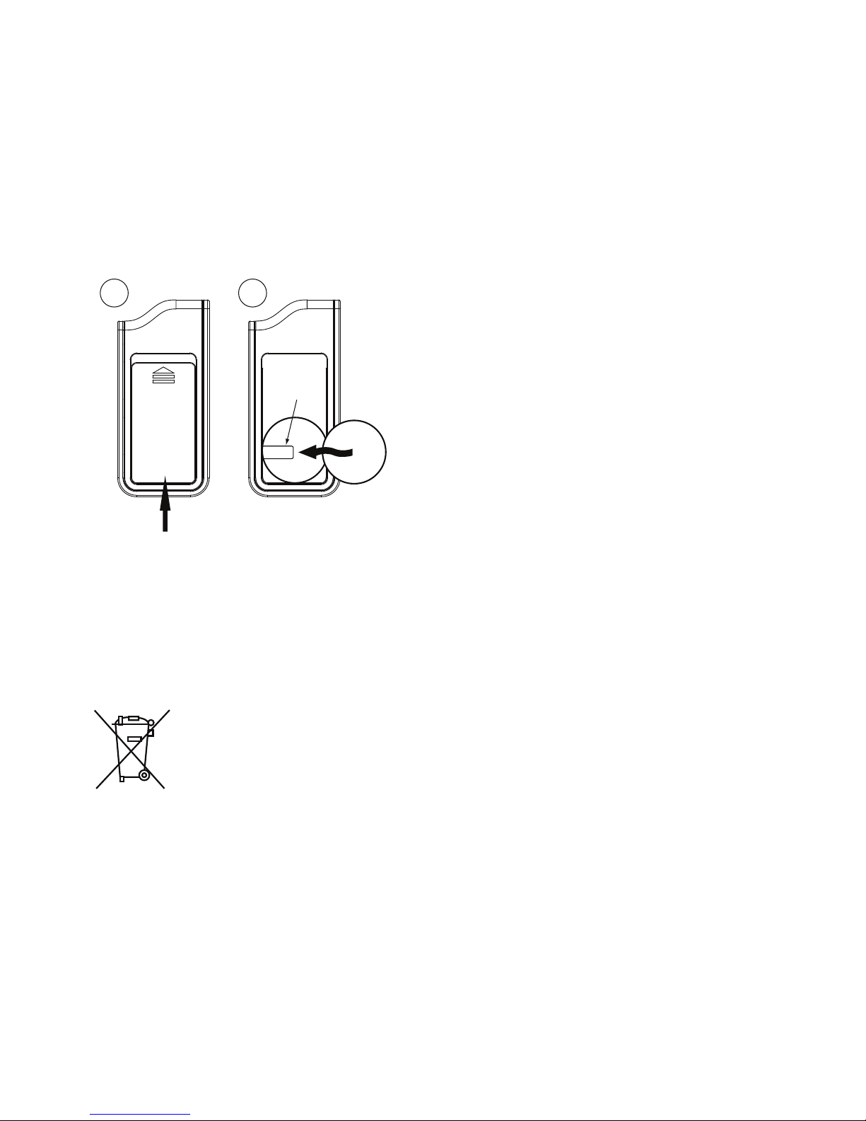
Battery Replacement
Rear View
1
2
1. Slide the battery cover up by applying equal pressure at its top and
bottom (the arrow on the cover indi-
Battery
Clip
Battery
Cover
cates the direction), remove the cover
from the remote control housing.
+
2. Gently pry up on the battery to remove it from the holder. Insert a new
battery into the holder and under the
clip with the positive (+) side up. Replace the battery cover. The remote control is now ready for use.
Battery Disposal
Directed Electronics cares about the environment. If you
need to dispose of the battery, please do so in accordance
with your municipal requirements for battery disposal.
© 2011 Directed Electronics. All rights reserved.
41
Page 45

Glossary of Terms
Document Terminology
Control Module The “brain” of your system. Usually hidden underneath the
dash area of the vehicle. It houses the microprocessor which
monitors your vehicle and controls all of the system’s functions.
Responder LE (2-way
Remote Control)
Companion Remote
(1-way Remote Control)
Control Center The control center contains the system’s radio-frequency an-
Status LED A light used to indicate the status of your system. It is located
Control Button A small push button located on your system’s control center.
A hand-held, remote control which operates the various functions of your system and receives messages and pages from
the system.
A hand-held, remote control which operates the various functions of your system but does not provide message display..
tenna, the control button, and the Status LED. For maximum
remote-control range, the control center is usually located at
the top of the windshield, centered near the rear-view mirror.
on your system’s Control Center.
It is used to override (disarm) the alarm when a remote is not
available or to enter or exit Valet Mode.
42
© 2011 Directed Electronics. All rights reserved.
Page 46

Patent Information
This product is covered by one or more of the following United States
patents:
Remote Start Patents:
5,349,931; 5,872,519; 5,914,667; 5,952,933; 5,945,936;
5,990,786; 6,028,372; 6,467,448; 6,561,151; 7,191,053;
7,483,783
Vehicle Security Patents:
5,467,070; 5,532,670; 5,534,845; 5,563,576; 5,646,591;
5,650,774; 5,673,017; 5,712,638; 5,872,519; 5,914,667;
5,952,933; 5,945,936; 5,990,786; 6,028,505; 6,452,484
Other patents pending.
Page 47

Government Regulations
This device complies with Part 15 of FCC rules. Operation is subject to the following two conditions: (1) This device may not cause harmful interference, and
(2) This device must accept any interference received, including interference
that may cause undesirable operation.
This equipment has been tested and found to comply with the limits for a class B
digital device, pursuant to Part 15 of the FCC Rules. These limits are designed
to provide reasonable protection against harmful interference in a residential
installation. This equipment generates and can radiate radio frequency energy and, if not installed and used in accordance with the instruction manual,
may cause harmful interference to radio communications. However, there is
no guarantee that interference will not occur in a particular installation. If this
equipment does cause harmful interference to radio or television, which can be
determined by turning the equipment OFF and ON, the user is encouraged to
try to correct the interference by one or more of the following measures:
s2EORIENTORRELOCATETHERECEIVINGANTENNA
s)NCREASETHESEPARATIONBETWEENTHEEQUIPMENTANDRECEIVER
s#ONNECTTHEEQUIPMENTINTOANOUTLETONACIRCUITDIFFERENTFROMTHATTOWHICH
the receiver is connected.
s#ONSULTTHEDEALERORANEXPERIENCEDRADIO46TECHNICIANFORHELP
Remote Controls
To satisfy FCC RF exposure compliance requirements, this device should be
used in hand-held, hand operated configurations only. The device and its antenna must maintain a separation distance of 20 cm or more from the person’s
body, except for the hand and wrists, to satisfy RF exposure compliance. This
device is designed to be used in a person’s hands and its operating configurations do not support normal transmissions while it is carried in pockets or
holsters next to a person’s body.
44
© 2011 Directed Electronics. All rights reserved.
Page 48

Control Center
To satisfy FCC RF exposure compliance requirements, the device and its antenna must maintain a separation distance of 20 cm or more from the person’s
body, except for the hand and wrists, to satisfy RF exposure compliance.
This device complies with the Industry Canada Radio Standards Specification
RSS 210. Its use is authorized only on a no-interference, no-protection basis;
in other words, this device must not be used if it is determined that it causes
harmful interference to services authorized by IC. In addition, the user of this
device must accept any radio interference that may be received, even if this
interference could affect the operation of the device.
WARNING! Changes or modifications not expressly approved by the party
responsible for compliance could void the user’s authority to operate this device.
Safety
© 2011 Directed Electronics. All rights reserved.
45
Page 49

Warning! Safety First
Please read the safety warnings below before proceeding. Improper
use of the product may be dangerous or illegal.
Installation
Due to the complexity of this system, installation of this product must only be
performed by an authorized Directed dealer. If you have any questions, ask
your retailer or contact Directed directly at 1-800-753-0600.
Remote Start Capable
When properly installed, this system can start the vehicle via a command
signal from the remote control transmitter. Therefore, never operate the system
in an enclosed area or partially enclosed area without ventilation (such as a
garage). When parking in an enclosed or partially enclosed area or when
having the vehicle serviced, the remote start system must be disabled using the
installed menu wheel. It is the user’s sole responsibility to properly handle and
keep out of reach from children all remote control transmitters to assure that the
system does not unintentionally remote start the vehicle. THE USER MUST INSTALL A CARBON MONOXIDE DETECTOR IN OR ABOUT THE LIVING AREA
ADJACENT TO THE VEHICLE. ALL DOORS LEADING FROM ADJACENT LIVING AREAS TO THE ENCLOSED OR PARTIALLY ENCLOSED VEHICLE STORAGE AREA MUST AT ALL TIMES REMAIN CLOSED. These precautions are the
sole responsibility of the user.
Manual Transmission Vehicles
Remote starters on manual transmission vehicles operate differently than those
with automatic transmission because you must leave your car in neutral. You
must read this Owner’s Guide to familiarize yourself with the proper procedures
regarding manual transmission remote starters. If you have any questions, ask
your authorized Directed dealer or contact Directed at 1-800-753-0600.
46
© 2011 Directed Electronics. All rights reserved.
Page 50

Before remote starting a manual transmission vehicle, be sure to:
s Leave the vehicle in neutral and be sure no one is standing in front or
behind the vehicle.
s Only remote start on a flat surface
s Have the parking brake fully engaged
WARNING! It is the responsibility of the owner to ensure the parking/emergency brake properly functions. Failure to do so can result in personal injury or
property damage. We recommend the owner have the parking / emergency
brake system inspected and adjusted by a qualified automotive shop biannually.
Use of this product in a manner contrary to its intended mode of operation may
result in property damage, personal injury, or death. (1) Never remotely start
the vehicle with the vehicle in gear, and (2) Never remotely start the vehicle
with the keys in the ignition. The user must also have the neutral safety feature
of the vehicle periodically checked, wherein the vehicle must not remotely start
while the car is in gear. This testing should be performed by an authorized
Directed dealer in accordance with the Safety Check outlined in the product
installation guide. If the vehicle starts in gear, cease remote start operation immediately and consult with the authorized Directed dealer to fix the problem.
After the remote start module has been installed, contact your authorized dealer
to have him or her test the remote start module by performing the Safety Check
outlined in the product installation guide. If the vehicle starts when performing
the Neutral Safety Shutdown Circuit test, the remote start unit has not been
properly installed. The remote start module must be removed or the installer
Safety
must properly reinstall the remote start system so that the vehicle does not start
in gear. All installations must be performed by an authorized Directed dealer.
OPERATION OF THE REMOTE START MODULE IF THE VEHICLE STARTS IN
© 2011 Directed Electronics. All rights reserved.
47
Page 51

GEAR IS CONTRARY TO ITS INTENDED MODE OF OPERATION. OPERATING THE REMOTE START SYSTEM UNDER THESE CONDITIONS MAY
RESULT IN PROPERTY DAMAGE OR PERSONAL INJURY. YOU MUST IMMEDIATELY CEASE THE USE OF THE UNIT AND SEEK THE ASSISTANCE OF AN
AUTHORIZED Directed DEALER TO REPAIR OR DISCONNECT THE INSTALLED
REMOTE START MODULE. DIRECTED WILL NOT BE HELD RESPONSIBLE OR
PAY FOR INSTALLATION OR REINSTALLATION COSTS.
This product is designed for fuel injected vehicles only. Use of this
product in a standard transmission vehicle must be in strict accordance
with this guide.
This product should not be installed in any convertible vehicles, soft or
hard top with a manual transmission. Installation in such vehicles may
pose certain risk.
Interference
All radio devices are subject to interference which could affect proper
performance.
Upgrades
Any upgrades to this product must be performed by an authorized
Directed dealer. Do not attempt to perform any unauthorized modifications to this product.
Water/Heat Resistance
This product is not designed to be water and/or heat-resistant. Please
take care to keep this product dry and away from heat sources. Any
damage from water or heat will void the warranty.
48
© 2011 Directed Electronics. All rights reserved.
Page 52

Limited lifetime consumer warranty
Directed Electronics. (“Directed”) promises to the original purchaser to repair or replace
(at Directed’s election) with a comparable reconditioned model any Directed unit (hereafter the “unit”), excluding without limitation the siren, the remote transmitters, the associated
sensors and accessories, which proves to be defective in workmanship or material under
reasonable use during the lifetime of the vehicle provided the following conditions are met:
the unit was purchased from an authorized Directed dealer, the unit was professionally
installed and serviced by an authorized Directed dealer; the unit will be profession¬ally
reinstalled in the vehicle in which it was originally installed by an authorized Directed
dealer; and the unit is returned to Directed, shipping prepaid with a legible copy of the
bill of sale or other dated proof of purchase bearing the following information: consumer’s
name, telephone number and address; the authorized dealers name, telephone number
and address; complete product description, including accessories; the year, make and
model of the vehicle; vehicle license number and vehicle identification number. All components other than the unit, including without limitation the siren, the remote transmitters
and the associated sensors and accessories, carry a one-year warranty from the date of
purchase of the same. ALL PRODUCTS RECEIVED BY DIRECTED FOR WARRANTY REPAIR
WITHOUT PROOF OF PURCHASE FROM AN AUTHORIZED DEALER WILL BE DENIED.
This warranty is non-transferable and is automatically void if: the unit’s date code or serial
number is defaced, missing or altered; the unit has been modified or used in a manner
contrary to its intended purpose; the unit has been damaged by accident, unreasonable
use, neglect, improper service, installation or other causes not arising out of defects in
materials or construction. The warranty does not cover damage to the unit caused by
installation or removal of the unit. Directed, in its sole discretion, will determine what constitutes excessive damage and may refuse the return of any unit with excessive damage.
TO THE MAXIMUM EXTENT ALLOWED BY LAW, ALL WARRANTIES, INCLUDING
BUT NOT LIMITED TO EXPRESS WARRANTY, IMPLIED WARRANTY, WARRANTY
OF MERCHANTABILITY, FITNESS FOR PARTICULAR PURPOSE AND WARRANTY OF
NON-INFRINGEMENT OF INTELLECTUAL PROPERTY, ARE EXPRESSLY EXCLUDED;
AND DIRECTED NEITHER ASSUMES NOR AUTHORIZES ANY PERSON OR ENTITY
TO ASSUME FOR IT ANY DUTY, OBLIGATION OR LIABILITY IN CONNECTION
WITH ITS PRODUCTS. DIRECTED DISCLAIMS AND HAS ABSOLUTELY NO LIABILITY
FOR ANY AND ALL ACTS OF THIRD PARTIES INCLUDING ITS AUTHORIZED
DEALERS OR INSTALLERS. DIRECTED SECURITY SYSTEMS, INCLUDING THIS UNIT,
ARE DETERRENTS AGAINST POSSIBLE THEFT. DIRECTED IS NOT OFFERING A
GUARANTEE OR INSURANCE AGAINST VANDALISM, DAMAGE OR THEFT OF THE
AUTOMOBILE, ITS PARTS OR CONTENTS; AND HEREBY EXPRESSLY DISCLAIMS ANY
LIABILITY WHATSOEVER, INCLUDING WITHOUT LIMITATION, LIABILITY FOR THEFT,
DAMAGE AND/OR VANDALISM. THIS WARRANTY DOES NOT COVER LABOR
COSTS FOR MAINTENANCE, REMOVAL OR REINSTALLATION OF THE UNIT OR
© 2011 Directed Electronics. All rights reserved.
49
Page 53

ANY CONSEQUENTIAL DAMAGES OF ANY KIND. IN THE EVENT OF A CLAIM
OR A DISPUTE INVOLVING DIRECTED OR ITS SUBSIDIARY, THE VENUE SHALL BE
SAN DIEGO COUNTY IN THE STATE OF CALIFORNIA. CALIFORNIA STATE LAWS
AND APPLICABLE FEDERAL LAWS SHALL APPLY AND GOVERN THE DISPUTE. THE
MAXIMUM RECOVERY UNDER ANY CLAIM AGAINST DIRECTED SHALL BE STRICTLY
LIMITED TO THE AUTHORIZED DIRECTED DEALER’S PURCHASE PRICE OF THE UNIT.
DIRECTED SHALL NOT BE RESPONSIBLE FOR ANY DAMAGES WHATSOEVER,
INCLUDING BUT NOT LIMITED TO, ANY CONSEQUENTIAL DAMAGES, INCIDENTAL
DAMAGES, DAMAGE TO VEHICLE, DAMAGES FOR THE LOSS OF TIME, LOSS OF
EARNINGS, COMMERCIAL LOSS, LOSS OF ECONOMIC OPPORTUNITY AND THE
LIKE. NOTWITHSTANDING THE ABOVE, THE MANUFACTURER DOES OFFER A
LIMITED WARRANTY TO REPLACE OR REPAIR THE CONTROL MODULE SUBJECT TO
THE CONDITIONS AS DESCRIBED HEREIN. THIS WARRANTY IS VOID IF THE UNIT
HAS NOT BEEN PURCHASED FROM DIRECTED, OR AN AUTHORIZED DIRECTED
DEALER, OR IF THE UNIT HAS BEEN DAMAGED BY ACCIDENT, UNREASONABLE
USE, NEGLIGENCE, ACTS OF GOD, NEGLECT, IMPROPER SERVICE, OR OTHER
CAUSES NOT ARISING OUT OF DEFECT IN MATERIALS OR CONSTRUCTION.
Some states do not allow limitations on how long an implied warranty will last or the
exclusion or limitation of incidental or consequential damages. This warranty gives you
specific legal rights and you may also have other rights that vary from State to State.
This warranty is only valid for sale of product(s) within the United States of America and
in Canada. Product(s) sold outside of the United States of America or Canada are sold
“AS-IS” and shall have NO WARRANTY, express or implied.
For further details relating to warranty information of Directed products, please visit the
support section of Directed’s website at: www.directed.com
This product may be covered by a Guaranteed Protection Plan (“GPP”). See your
authorized Directed dealer for details of the plan or call Directed Customer Service at
1-800-876-0800.
920-10011-01 2011-06
50
© 2011 Directed Electronics. All rights reserved.
Page 54
Quick Reference Install Guide
1
Security
and
Remote
Start
_j
Responder
LE
------
Wiring
Connections
Re
mote
S
tart
1
0-
pin
H
arn
e
ss
r-
fiujdeJr.ansiatiODL
____
__
__ ·
__
~---·--·----
-·--
··--
-
For a Spanish or
French
version
of
the
Ins
tallation
G
Jid
e,
please download
-1
fr
om
·-
----·----
·--·
--
---
_j
Vv\lv'IN.dir
ectechs.com under
"Resou
rces"
Troducci
6n
de
los monuoles:
Para obten
er
uno
ve
rsiOn
en
Espanol o
F
ra
nc
es
del tv'lanuol
de
lnstal
oci6
n, desc
6r
-
guelo
de
\t'I'NW
.di
rectechs
.
com
bajo
el ti·ulo
"R
ecu
r
sos~
[
"Resou
r
ces#
).
Tradu
ct
ion
du
gui
de
Po
ur
une version
fran<;aise
au
espognole
du g ui
de
d'instollation, veuillez le
1
&-
lec
h
or
g
P.r
n
www.d
irectechs.
com
sous
«Re.sowc:es:..
~
-..
Bi
tw
rit
er
/SmartSt
art
Port
---.-
Thermi
storfTe
mp
Sen
sor
.
__..........
Sensor
1
--~
Sensor2
~
-
-~
Control
Cente
r
Main
6-
pin
Doo
r Lock
D
2D
Port
(f
or
external
X
pre~
~
kit
interface modul
e)
Harness Po
rt
Aux/Shu
tdown!Trigger
24
-pin H
arness
0
2011
DirE'CiedE
iear
on
i(s.A
II
r
ight>Reoc
rvC'd
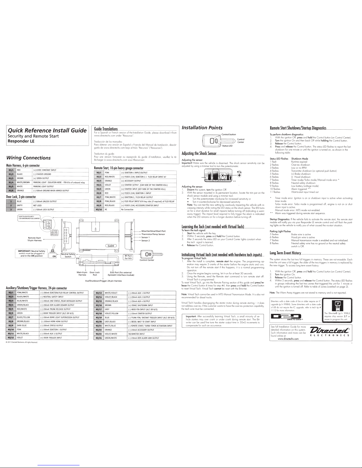
Installation
Points
Co
ntr
ol
Center
Adius.tin~the.shodUenw_
__
________
_____
_ _
Ad
j
u~ting
the
senso
r:
I
mpo
rt
an
t!
Make su
re
th
e
vehicle is disarm
ed
The shock sensor
sens
il
ivily con be
ad
justed by us
in
g a
tr
i
mm
er
toollo
tu
rn
the poten
ti
omel
er.
~~
-n+;;;±
ffi
Adjusti
ng
the sensor:
1
Disarm !he
sys
lem. turn the i
gn
it
io
n
Off
2
W ith the
senso
r mounted in i
ts
permane
nt
l
oca
tion,
l
oc
a
le
the
tr
im
po
l on
th
e
shock
sensor
module
and using a trim
me
r
tCX>
I:
Tu
rn
the polentiometer
clockwise
fo
r
in
creased
sensi
tivity or
Turn
it
co
unterclockwise for
dec
reased
se
n
sit
ivity
Note: You
co
n
te
st the
new
se
tt
ing by cautiously impacting
lhe vehicle
wit
h in-
creasing intensity
while
no
t
in
g
the
LED
status on the sh
oc
k
senso
r_
Th
e
LED
t
urns
on
for a
sh
ort duration for
smell impacts before turning
off (indicating o
wa
rn
·
awa
y trigge
r).
The impact
level
required to
fu
ll
y
tri
gge
r
the
alarm
is indicated
when
the L
ED
remains
on
for a longer duration before turning off.
Learning
thelilchlnotne.eded.witllYirt
....
u
aLLJIJ
...
acJJJbl
~~
~
To
learn
the
tach signa l:
1.
Sta
rt
the
vehicle
with the key_
2.
W ithin
5
seconds,
pre
ss
and
ho
ld
the
Co
ntrol
button
3.
Af
ter
3
seconds
th
e status
LED
on
your
Control Center
lights constant when
the tach signal
is
lea
rn
ed.
4.
Re
lease
the
Co
ntrol
butto
n.
Initializing
Virtu
al
Tachlnotne_e.derl..w
.ith.h
or
.dwir
eJorh..inp.uls)_
To
progra
m
Virtual
T
ac
h:
1
After
th
e in
stal
l is complele, remote start
th
e eng
in
e. The p rogra
mm
ing
o
p-
eration may require
3
cranks of the starter before
th
e engine
starts
and r
uns.
Do
not tu
rn
off
th
e remote st
art
if
this happens, it is a n
or
mal programm
in
g
operation.
2.
O n
ce
t
he
engine
be
gi
ns
ru
nning,
let
it
ru
n f
or
at least
30
seconds.
3.
Us
ing t
he
Remote, send the
Remo
te start
co
Mm
an
d
to
tu
rn remote st
ar
t off
Vir
tual
Tac
h is progran med.
To reset Virtual Tach.
go
into the
Rem
ote
Pa
iring
section
of
thi
s guide and pr
ess
/r
e-
lease
the
C
or~t
r
o
l
bu
tton
4
li
mes
lor
step
#4,
th
en
p
ress
and
ho
ld
lhe
Con
trol
but
ton
to reset
Vir
h.J
ol
Ta
ch. Vi
rt
ual
Ta
ch cannot
be
r
ese
t
wi
th
th
e Bitwriter.
Note: Vi
rt
ual T
ac
h
ca
nn
el
be
us
ed
in MTS
Manua l Tra
nsm
i
ss
io
n
Mode
.
It
is also
not
recommended lor di
es
el tr
ucks
Vir
tua
l
Tach
ha
ndles d isen
gag
i
ng
l
he
st
ar
ler
motor
d
ur
ing
-emote
stm ling - it does
no
t a
dd
re
ss
over-r
ev.
If
the
customer wonts to have
th
e
o
ver-
'e
v
protecti
on
capab
il
ity,
th
e tach w ire must
be
connected
I
mpo
rt
ant:
After
succ
ess
fully learning
Vi
rtual Tach,
a
small mi n
or
ity o f
ve-
hicle
start
ers
may over crank or under cr
an
k du
ri
ng remote
start.
The
Bi
t-
w
ri
ter
co
n
be
used line tune
lhe
s
lo
rter o
ut
pu
t
ti
me in
50mS
increments to
compensate
for
such
an
occ
unence.
Rem
o
t
e_St.artShuidliWII/.5
t
o
rt
u
~'-p
...
Di"l:ogfll'
no~st~ics
..__~~
-
To
perform shutdo
wn
diagnostics:
1 W ith the ig ni
ti
on
Off,
pre
ss
and
ho
ld
th
e Co ntrol bu tton (on C
on
lrol Cente
r)
.
2.
Turn the igni
ti
on
O n
and
th
en
ba
ck
Off
wh
ile holding
th
e
Conl
rol
button.
3.
Releo
se
the
Control
button
4.
Pre
ss
and
release
the Control butto
n.
Th
e status L
ED
fl
ashes
to re
po
rt
th
e
lost
shut
down
f
or
one
mi
'"1
ute
or
unt
il
th
e ig nilion
is
tu
rn
ed
on,
as
sh
own
in the
foll
owing
t
ab
le
Status
L
ED
Fl
ashes
I f
las
h
2
/l
oshes
3
flashes
Shutdown
Mode
R
un
ti
me
expired
Ove
r-r
ev
shu
t
do
wn
Low o r no RPM
4
fl
ashes
5
flashes
Tran
sm
itter
sh
ut
do
wn
lor
op
tional push butto
n!
(+I
Broke
shu
td
own
6
fl
a
sh
es
1-1
Hood
shutd
own
7
fl
oshes
8
fl
osh
es
Ti
me
r m
ode
/
Tu
rbo m
ode
/
Manua
l m
ode
error
"
Neu
tral
sa
fety shutd
own
9
flashes
l
ow
battery {volt
age
m
od
el
10
flas
hes
Alarm trig
ge
r
ed
*"'
11
fl
m hes
Wa
i
t-
to-st
art input tim
ed
oul
Tim
er mode e rro
r:
Igni
ti
on is
on or
sh
utdown input is active
whe
n activating
timer mode.
Turb
o
'Tlode
error: Tur
bo
m
ode
is
pr
og
rammed
off
,
engine is not on o r
shu
l-
dow n inp
ut
is active
N\anu
ol
mode e
rr
or: MTS
m
ode
not en
ab
l
ed
Alarm
was tri
gge
red du
rin
g remote sta
rt
sequen
ce
.
Startup
Diagnostics:
lithe
vehicle
fails to
oclivate
the remote
sta rt,
the remole
slarl
module
wi
ll
notify you via
yo
ur Responder LE remote
co
ntro
l and
will flash
the
pa
r
k-
ing
lights
on
the
vehicle to no
ti
fy
yo
u
of
wh
ol caused the
no-s
ta
rt
situati
on
.
P
ark
i
ng
L
ig
ht
Flashes
5
fla
sh
es
Brake wire is
ac
tive
6
fl
ashes
Hood
pin w ire is
ac
tive
7
Hash
es
Alla
nu
al
transmission mode is e
nab
led and
no
t initiali
zed
8
Ras
hes
Neutral
safety
wire has
no ground or the
neu
tr
al
safety
switch is
Off
.
~
e.rtrllientJiisto
J¥-
.....
-
--
--
--·-
-·
T
he
system stor
es
the lost
tvv
o
full
tr
iggers in memo
ry
. T
hese
ore not
erma ble.
Each
ti
me
th
e
un
it
sees
a fu
ll
tr
i
gge
r,
the older of
th
e
tw
o
!rigge
rs
in memory is re
pl
ace
d
by
the n
ew
tr
ig
ge
r.
To access long term eve
nt
hi
slo
ry
:
1
W i
th
the ignitio n
Off,
press and
ho
ld
th
e Co ntrol b
utt
on (on
Con
trol
Ce
nte
r)
.
2.
Tu
rn
the ignition
On
3.
Re
lease
the
Co
nt
rol
button.
4.
Wi
thin
5
seconds, pr
ess
and
release
the
Co ntrol
bu
tto
n.
The
sta
t
us
lED
Rash
es
in groups indi
ca
ting the lost
two
zones that tr
ig
gered the
un
it for
1
mi
nu
te or
until the
ig
nition
is
turned
off
. Refer to
table
of zo n
es
(overleaf
on
page
2
).
N
ote:
Th
e
Worn
Away triggers ore not stored to memory and is not re
po
rt
ed
.
Bitwrilers
wi
th
o
da
te code of
6o
or
ol
der
req
ui
re
on
IC
upgrade
(p
/ n
99
8MI
Some
bi
l\.vrit
e
rs
with
a do
te
code
ol
6B
do
not
·
equ
ire
the
IC
u
pgrad
e,
refer
to
t
ec
h tip
#
1112 for mo
re
info
n
na
ti
on.
1?1
The
B
itvv
riter® !p/ n
99
8UI
requi
re
s
ch
ip
versi
on
2.7
or
newer to program
thi
s
un
it.
See
full Installa
ti
on
Gu
ide lor more
delail
ed
information o n t
hi
s sy
ste
m
S
uc
h information a nd
mo
re con
be
f
ou
nd online at:
Z'Uazeazd
•
E L E
C
T R
0
N I
C
S
www
.directechs.com
Page 55

~emleolw..ur..,.es
'--:--
The System Features Learn Routine dictates
how
the unit operates It
is
possible to
access a nd
change
most o f the featu re
set
tings using the
Cont
rol button
1 Open a door
2
Tum
the
ignition on ,
then
off
3. Select a Menu.
Press and
hold
the
Control b
utt
on.
The
number of sir
en
chirps
indicates the menu number. I chirp
indicates menu 1, 2 chirps - menu 2
and
3
chirps
for
menu
3
4 W h
en
the
desired
men
u chir
ps
ore heard, release
the
Control
button
5 . Select a Feature.
Press
and
release the Cont
rol button the number of times
correspondi
ng
to t
he
feature you wi
sh
to change.
Then
press a
nd
hold one
more time to select the features
6.
Program
the Feature.
Whi
le hold ing the
Contro
l button, you con pr
ogram the
feature using the remote control.
For
features with
on
ly
two
options;
~
=
op
tion 1
whi
le $ = option 2
For
features with more than
two opti
ons; Q selects
the options
in
ascending o rde
r,
whi
le $ selec ts them in descending order.
Note
: Pr
essing
{:)
button resets the feature to the f
actory default.
Once
o feature
is
programmed:
O ther features con
be
programmed w ithin the some menu
Ano
ther menu
con
be
selected
The
l
ea
rn
routine
con
be
exited if programm ing
is
complete
To
access
another
feature
in
the same menu:
1. Press
and
release the
Con
trol button the number of times necessary to
advance
from the feature you just
programmed
to the next o ne you
wan
t to
prog
ram
Then press the
Con
trol button once more
and
hold
it.
To
select
another
menu
:
1 Press
and
hold
the
Con
trol button
2.
Alter 3 seconds, the unit
adv
ances to the next menu a nd the siren ch i rps, indi-
cating
which
menu has been accessed
The
learn
routine exits
if
any
of
the
following
occurs:
The
open
door
is
dosed
The ign
iti
on is turned
On
There
is
no activity lor 30 seconds
The
Control button
is
pressed too
many
times
RitwriteL:Jlnly_Optinos_
H
If programming with the Bitwriter®, the learn rou tine can
be
locked or un·
locke
d.
If
the learn routine has previously been
l~k
ed,
it
mus
t
be
un
locked
w
1t
h B1twriter® · this cannot
be
done
manually
w1th
the
Con
trol button
The Bi
tw
rit
er®
11!11
gives you access to a
wider
range
of
sys
tem option
s.
These
features
and
the ad justments that
may
be
progr
ammed
are
described
in
the table
below.
Default settings are
in
bold
type
0
2011
Direded
Electronics.
All
rights
Re~d
Menu
2 -
Convenience
feotur:e_M.enus
Default settings ore
in
bold
type.
New
featu
res
are
bold
w ith
grey
backg
1ound.
Menu
l -
Security
Menu
3 -
Remote
stort
Remote
Pairing
Prepare the vehicle system to
be
Paired
with o new
remote
1
Open a doo
r
2 Turn the k
ey
to the
ON
position
3. W it
hi
n 5 seconds press an d release the
Con
trol button on the
Control Cen
ter
onetime.
4.
Within
5 seconds , press
and
hold
the
Con
trol button on the
Con
trol Center.
The status
LED
wil
l flash
one
time
and the siren then chi r
ps
to
conf
irm the vehicle
is ready
for remote pairing.
Release the
Con
trol button
and proceed bel
ow.
Note:
If no r
emo
te pair ing re
sults,
the system
will
exit a her
60
seconds.
Prepare the
new
remote to
be
Paired
with
the system
Remo
te Pair matches your LE remote to the
sys
tem.
Make
sure the LE remote
is
set
lor
t
he
desired
Cor
1 (Defoul
tL
or
Cor 2 operat
ion l
o. r 1he
system
it w ill
be
paired
with
1
Press
and
hold
the f button for 8 seconds
Note:
The LOCK
LED
indicator w ill t
urn
on at 3 seconds. Please disr
egard and
continue to
hold
Wait lor
the Transmit lED to lig
ht
sol
id
and
the remote to
beep
_ Release the j
button
3.
Press the
{:') for
1 second. The tra nsmit lED
will
bli
nk
3 times
and
beep
3
times
4.
Withi
n 5 seconds, press the Q button.
5.
The vehicle siren w ill chirp
and
the lED i ndi
cato
rs on the remote w ill light
in
se
quence with sound.
You
hove
now
successfully learned the remote to the
vehicl e remote start
and
security system.
6.
Press
the j b utton
two tim
es to ex it learn routine on the remote. The transmit
LED wil
l
turn
off
and
exit tone w ill sound ..
Note:
Please see installation gui
de
for pairing with the 1-woy
companion
remote.
Toble_oflones_
A
zone
is
represented
:~s~m~~~o ~?ent~fy
.
a
f~H'
oili:ri~
o:sv:;"'···••l>J&';·i;
~~~:·
¥~tiZl~~
T~~~?.I~rt
Twnk Pi
n H
2/19
Bl
ue
wire
I
ns
tant tr
igg
er: a heavier i mpact
detected by the onboord
sh
ock sensor
Door switch
trigge
r
I
nstant lr
igge
r:
For
op1
1ono l
senso
rs
Ignition
tr
igge1
Hood
Pin
On
board shock
sensor.
H2
/6
Green or
H2
/12
Vi
olel w i
re
Opl
ional
MUX
port
H3/
l Pi
nk
wire
H2/
17 Grey
wi
re
QRNil04l011~
LADS2040
Page 56

FREE
REPLACEMENT
THANKS
2-WAY
Directed Electronics would like to reword your
Responder
Please login to
following
batteries, courtesy
(must
FOR
PURCHASING
SECURITY & REMOTE
REGISTER
LE
FREE
register within
REPlACEMENT
CODE
purchase by offering you
the
to register for free replacement
TODAY!
URL
of
60
days
BATTERIES
THE
START
BATIERIES
below
Directed Electronics.
and
of
your purchase)
ULTIMATE
SYSTEM.
.
enter the
www.pythoncarsecurity.com/Evolution
LAD502Pl
540
-1 0005-02
Page 57

VEHICLE EQUIPPED
WITH
A DEl® REMOTE
START
SYSTEM
If vehicle
battery is disconnected, the system may attempt to start when the battery is reconnected or transmitter
is used. Press brake to disengage. Check with
vehicle owner to determine if hood pin switch or override switch
was
installed
to disengage the system for service.
IMPORTANT
SAFETY
NOTICE
Page 58

Page 59

z;i
·
PRODUCT
REGISTRATION
E L E C T R 0 N I C
S,
I N C.
Security
Register your product for:
~
Recall Notifications
We
contact
our
customers
in
case
of
recall.
~
Owner
Verification
Registration
can
serve
as
verification
of
your
ownership
in
the
event
of
product
theft
or
loss.
~
Efficient Service
Completing
this
card
will
help
you
obtain
more
efficient
warranty
service
in
case
there
is a problem
with
your
product.
Don't forget
We
know
you
are
busy,
but
registering
is
important,
quick
and
easy!
Or
register
online
at
www.prodregister.com/directed
Page 60

Vbre~·
ELECTRONICS,
1.
1.
D
Mr.
2. 0 Mr11
First
name
. 3. D
INC.
IMPORTANT! IMPORTANT!
Please
complete
or
register
Ms
.
4. D
Miss
Initial
Last
name
and
return
online
at
within
www.prodregister.com/directed
the
next
10
days
X F J
01
2.
3.
4.
5.
6.
7.
8.
9.
1
0.
11.
12.
Street
City
E-mail
Your
Martial
Date
Month
Model
Name
Price
Which
1.
2.
3. D
What
1. D
2. D
3. D
4. D
In
what
Vehicle
1.
2. D
3. D
4. D
5. D
Make
Model
VINI:
Year
:
How
01
. D
02
. D
03
. D
04
. D
05
. D
06
. D
What
01
. D
02.
03
. D
04
. D
05
. D
06
. D
07
. D
08.
09
. D
address
date
ol
birth
status
:
of
purchase
I I
number
:
of
store
where
paid
(excluding
Directed
D
Autostart
D
Avital
Clifford
type
of
product
Security
Security
Remote
Keyless
vehicle
type:
D
Car
Truck
SUV
Van
Minivan
ol
vehicle
name:
did
you
tim
Local
Yellow
Magazine
advertisement
1V
commercial
Magazine
review
Friend/Relative's
recommendation
factors
most
Directed
reputation
D
Brand
Experience
Directed
Experience
Value/Price
Warranty
Special
Quality/Ourability
D
Sound
demo
:
Month
1.
D
Married
:
Day
purchased
sates
tax)
Electronics
brand
did
you
system
system
with
start
system
entry
system
will
this
product
:
become
aware
newspaper
pages
article
/
Influenced
Electronics
reputation
with
product
with
dealer
features
board/In-vehicle
/
Ye
ar
:
: $
did
you
4.
D
5. D
purchase?
remote
start
be
used?
6. D
7.
D
8.
D
9.
D
A. D
B. D
C. D Leased
0. D
of
this
07
. D
08
. D
09
. D
10
. D
11
. D
12
. D
the
purchase?
10
. D
11.
D
12.
D
13
. D
14
.
D
15.
D
16. D
17.
D
Yei!r
2.
D
Single
purchase?
Python
Viper
Motorcycle
Boat
Motor
home
Other
Bought
new
Bought
used
Leased
used
product?
(check
Radio
commercial
Salesperson
's
recommendation
Manufacturer's
website
Retailer
's
website
Internet
forum
Other
{check
up
Rebate/Promotion
Style/Design/Color
Dealer
proximity
Friend/Relative
recommendation
Salesperson's
recommendation
Ease
of
installation
Compatibility
vehicle
Other
to
.00
one)
three)
's
with
State/PrOvince
13.
What
benellts
this
product?
01
. D
02
. D
03.
D
04
. D
05
.
D
06
D
07.
D
08.
D
09
. D
10
. D
14.
What
other
this
purchase?
1.
D
2. D
3. D
4.
D
15.
Not
including
of
children
1. D
No
Male
Female
1.
D 2. D
1.
D 2. D
16.
OccupalionJEmploymenf
(check
all
Professional/Technical
Upper
management/Executive
Middle
management.
Sales/Marketing...........
ClericaVService
Tradesman/Machine
Teacher/Educator............
HeaHhcare • Physician/Nurse/Other ........
Homemaker
Military .............
Retired
..............
Se~
employed/Business
Work
from
17.
Which
group
01.
D
02
. D $15,000·$19,
03
. D
04
. D $30,000·$39,
05. D $40
06. D $50
07
. D
18.
Level
of
education: (check
1. D Completed
2. D
3. D
19.
For
your
1. D
20.
What
type
1. D
2. D
3. D DSL
4. D Other
5. D Satellite
21.
When
new
on
the
marl<et,
1. D
2. D
Zip/Postal
most
lnlluenced
(check
UP
to
Improved
security
Improved
convenience
Improved
pertormance
Compatibility
vehicle
Ease
Style/Design/Color
Special
Quality/Durability
Increase
Functionality
No
considered
Other
Electronics
Code
Audiovox
one else
that
Under
$20
$60
Completed
Completed
primary
Own?
Dial-up
Cable
Tend
Tend
while
with
of
installation
features
vehicle
brands
did
you
other
brands
Directed
brands
Alarm
yourself
,
what
and
other
adults
in
household
Age
apply)
. D
worker
............
operator/Laborer
....
..
..........
......
..........
.......................
owner ...
home
office ...
describes
your
$15,000
999
,000·$29,
999 10. D
999 11. D
,000·$49,999 12. D
,000·$59,999
,000·$74,999 14. D
high
college
graduate
residence. do
2. D
of
Internet
access
broadband
products
that
do
you
or
to
buy
such
to wait
until
before
buying?
Apt.
code
your
three)
11.
12.
13
14.
15
16
value
17
seriously
5.
6. D
7. D
8. D
9. D
10
is
the
GENDER
living
In
Male
yrs
.
1. D 2.
yrs
.
1.
D 2. D
status:
...........
.........
........
.
annual
08.
09
. D $100,000·$124,
13. D $200
highest/eve/
school
school
you
Rent?
do
you
(e.g. fiber
have
the
latest
someone
In
items
as
the
item
decision
to
purchase
D
Warranty
D
Price/Value
.
Rebate/Promotion
D
D
Immediate
availability
Friend/Relative
. D
recommendation
Salesperson's
. D
recommendation
. D
Dealer
proximity
consider
before
D
Auto
Page
Compustar
Prestige
Pursuit
Crime
Stopper
.
Bulldog
D
and
AGE
household?
D
Child
(in
under 1 year
Age
your
2.
Female
D
You
01
.
D
02.
D
03
.
D
04
.
. . D
05
.
...
D
06
.
...
D
07
.
D
08
.
09
.
D
10
.
D
D
.
11
.
D
12
.
D
13
.
family
Income?
D $75,000·$99,999
$125
,000·$149,
$150
,000·$174,
$175
,000·$199,
,000·$249,
$250,000
&
completed)
:
use
at
home?
optic,
wireless Wi·Max)
technologies
your
household
soon
as
they
been
are
around
has
's
making
yean~)
yrs
.
yrs
.
Spouse
D
D
D
D
D
D
D
D
D
D
D
D
D
999
999
999
999
999
over
appear
:
available?
for
a
Page 61

22.
To
help
us
understand
our
customers'
lifestyles,
please
indicate
the
interests
and
activities
in
which
you
or
your
spouse
enjoy
participating
on
a
regular
basis.
Home
Life
Travel
Great
Outdoors
01.
0
Grandchildren
15.
0
Airline
club/Frequent
flyer
27.
0
Hunting/Shooting
02.
D
Home
improvemenVDo-it-yourself
16.
D
Travel
in
USA
28.
D
Fishing
03.
D
Gardening
17.
D
Foreign
1ravel
29.
D
Camping/Hiking
04.
D
Own
a
dog
18.
D
Cruise
ship
vacations
30.
D
Wildlife/Environmental
issues
05.
D
Own
a
cat
19.
D
RV
vacations
31.
0
Boating/Sailing
Leisure
20.
0
Casino
gambling
Sports,
Fitness
&
Health
06.
0
Cultural/Art
events
Investing
and
Money
32.
D
Physical
fitness/Exercise
07.
D
Avid
book
reading
21.
D
Shopping
by
catalog/mail
order
33.
D
Walking
for
health
08.
0
Bible/Devotional
reading
22.
D
Shopping
by
internet
34.
0
Health/Natural
foods
09.
D
Gourmet
cooking/Fine
foods
23.
D
Use
credit
cards
regularly
35.
D
Dieting/Weight
control
10.
D
Wines
24.
D
Donate
to
charitable
causes
36.
0
Self-improvement
11.
D
Art/Antique
collecting
25.
D
Investments/Money
making
37.
0
Golf
12.
0
Stamp/Coin
collecting
opportunities
38.
0
Biking
13.
0
Crafts
26.
D
Contests/Sweepstakes
39.
0
Snowboarding/Snow
skiing
14.
0
Sewing/Needlework/Knitting
40.
D
NASCA
A
Thanks
for
taking
the
time
to
fill
out
this
questionnaire.
Your
answers
will
be
used
for
market
research
studies
and
reports.
They
will
also
allow
you
to
receive
important
mailings
and
special
offers
from
a
number
of
fine
companies
whose
products
and
services
relate
directly
to
the
specific
interests,
hobbies,
and
other
information
indicated
above.
Through
this
selective
program,
you
will
be
able
to
obtain
more
information
about
activities
in
which
you
are
involved
and
less
about
those
in
which
you
are
not.
Please
check
here
if,
for
some
reason,
you
would
prefer
not
to
participate
in
this
opportunity.
0
Failure
to
return
this
card
will
not
diminish
your
warranty
rights.
Copyright
©
2009 All
Rights Reserved
•
540-Q070
(A)
Please seal with tape. Do not staple.
LRDEI006
Page 62
Please
send
products
and
other
correspondence
to:
Directed
Electronics
Inc.
1
Viper
Way
Vista,
CA
92081
X
FJ
01
E L E C
T
R
0
N I
C
S,
I N
C.
PO
BOX
17
4391
DENVER
CO
80217-4391
··
,
{
-
~:
,
PostOffice;wU
t '
' , '
notdetiyer
,
? '
withogt
~r~p.~~
,
postage~
?
i;
.,,,,,,
,,,
I I
I I
I
I
I I
I I I I I
I
I
I
I I I
I I I
I I I
I
I
I
I I
I
I I
I I
I
I
I
I
I I I I I
I I I
I
I
I I I I I
I I
I
I
I
I
I
I
 Loading...