

Page 1
MOD
991
E L
Page 2
Congratulations on
the
purchase of your state-of-the-art security and
remote start
system
tures.
http://www.pythoncarsecurity.com
gUide information.
For
dealer or contact Directed at
will help maximize the
For
any additional questions please contact your authorized Directed
system.
more information please visit
Reading
this
Owner's
use
of your
-
the
Guide
system
belovv'
For
general and additional
1-800-753-0600.
prior
and
'vvebsite:
to
its
using your
many fea-
~
Welcome
system
containseverythi
to
the
best generation of security with
ng
you need.
remote start.
Your
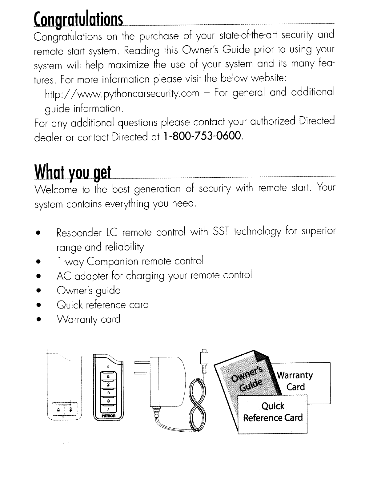
• Responder
range and reliability
•
•
• Owner's gUide
•
•
l-way
AC
adapter for charging your remote control
Quick
Warranty
Q ;
~
....
;·!J·
i
~
I
._-~-}
Companion remote control
reference card
LC
card
f
PVIIIDII
remote control with
SST
technology for superior
Quick
Reference
Card
Page 3
Government
.
~,
:
L..L1
Regulations
and
Safety
information
Your
Your
you receive the warranty registration card and proof
your dealer indicating the product was installed
Directed dealer.
days
com/directed
Quick
Carry
Replocement
If
Warranty
Responder
of
purchase.
Reference
this
card with you to reference your
additional remote controls are desired, please
LC
system
Your
or complete
product warranty
You
Cord
remote
controls
comes with a warranty. Please make sure
must
can validate it online at www.prodregister.
and
return
the warranty registration card.
be validated within 10
system's
see
of
purchase from
by
an authorized
many features.
your authorized
dealer or visit
are:
the
optional Responder
7752P
companion remote control.
us
at
for Responder
www.directedstore.com to order. Part numbers
LC
HD
color
2-way
Your
2-way
remote control
system
remote control
can also be used with
and
(7941P).
7652P
for
Page 4
Getting
Responder
Status
Using
Basic
Advanced
Advanced
Advanced
Advanced
ResponderLCconfiguration
Started 4
Charging
Keystousing
Screen
your
Commands
Performing
Responder
Fault
commands
Arm
Disarm
AUX/Trunk
Remote
commands:
Silent
AUX
Runtime
Temp
commands:
Sensor
RemoteValet
AUX
Timer
Runtime
commands:
Sensor
AUX
Smart
Alarm
commands:
Full
Silent
AUX
Defogger
Navigating
Button
Access
the
remote
this
manual 5
LC
2-Way
Icons
System
and
Confirmations
Commands
LC
Command
Condition
Start......................................................................................
Arm
Alerts
(Direct
Access)
(Level
1
Reset
Request
(Level
Bypass
2
Start
Remaining
(Level
Silent
Arm
3
Start
Report
(Level
Arm
4 22
menus
operation
menu
items
and
control:
table 12
1)
2)
3)
4)
'"
options
4
6
8
11
11
11
12
14
14
14
15
15
16
16
16
17
17
18
18
18
18
19
19
20
20
20
21
21
22
22
22
23
23
23
23
Page 5
Main Menu 24
Setup
Remote
Runtime
Car 2
Screen
Temp
Button
System
Clock
Review
Exit
Sensor
Pair
Demo
Power
Exit:
Alarm
Normal
Sensor
Full
Sensor
Full
Emergency
Trigger
Alarm
Alarm
Nuisance
Remote
Pit
Key
Remote
Disabling
Advanced
Temperature
Remote
Manual
Turbo
Remote
Features
Remote
Unit
Set
Remote:
mode:
Silent
Trigger
Start
Stop
Takeover
Timer
menu:
Start
Info
Alert
Color
Beep
Type
Adjust:
Off:
Arm
Silent
Protection
Arm
Arm
Protection
Warn-away
Messages
Override
Zone
Report
Report
Fault
when
when
Prevention
Features
Mode
Start
Safe-lock
Remote
Start
Reporting
Start
Time-out
Transmission
Mode
Start
Error
protection
Messages
Report..
disarming
requested
(NPC)
Start
Alert
Start
(MTS
mode)
24
25
26
26
26
26
27
27
27
27
27
27
28
28
,
29
29
30
30
30
31
31
31
31
32
32
33
33
34
34
34
35
35
35
36
37
37
38
39
Page 6
Remote
and
System
Operations
Passive Arming
Auto Re-orming
Valet
Mode
Power Save
Rapid
Automatic
Resume
Remote
Updates 4 1
OutofRange
No
Remote
Output
Feature not Available
40
40
40
41
41
41
42
42
42
1-way Companion
Remote
Control
Accessing Commands
Button Auto
Car
Select
Lock
Programming
Battery Information
System
Expansion Options
Battery Information (Responder
(l-Way)
LC)
Low Battery
Battery
Life
Battery Disposal
GlossaryofTerms
Government Regulations
Warning! Safety First
Installation
Remote
Start
Capable
Manual Transmission Vehicles
Interference
Upgrades and Batteries
Water/Heat
Resistance
Limited lifetime consumer warranty
43
44
44
44
45
46
47
49
49
50
51
52
54
56
56
56
56
58
58
58
59
Page 7
~~~--------_._"----------"-----------_."-----------".---------"--".
__
.-------
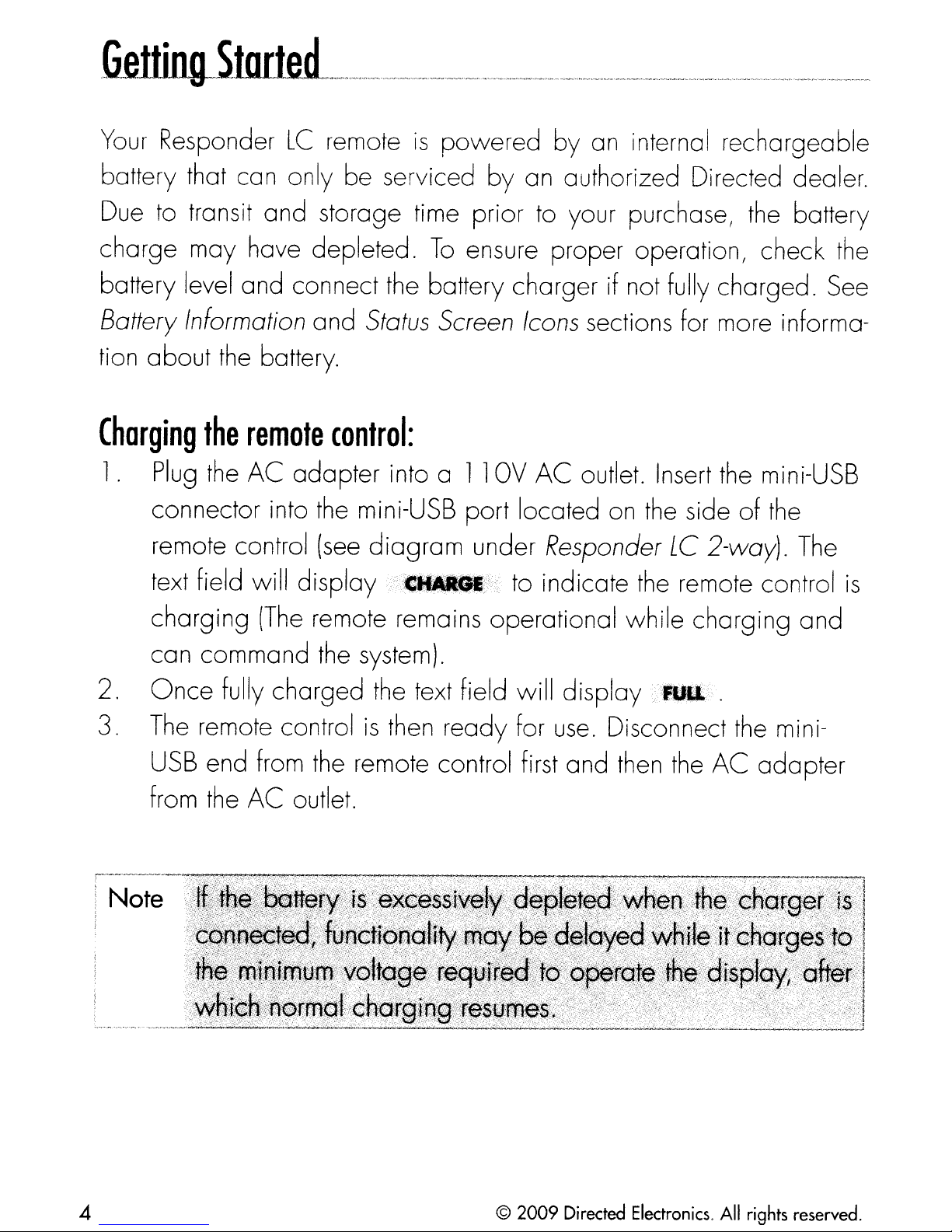
Your
battery that can only be serviced
Due to transit and storage time prior to your purchase, the battery
charge
battery level and connect the battery charger if not fully charged_See
Battery
tion about the battery.
Charging
1.
Responder
may have depleted_
Information
the
Plug
connector into the mini-USB port located on the side
remote control
text field will
the
LC
remote
and
remote
AC
control:
adapter
(see
display'''
is
To
Status
into a
diagram
Screen
••
powered
by
ensure proper operation, check the
11
OV
under Responder
''''
by
an internal rechargeable
an authorized Directed dealer_
Icons
AC
to indicate the remote control
sections for more informa-
outlet. Insert the mini-USB
LC
2-way). The
of
the
is
charging
can command the system).
2.
3. The remote control
Once
USB
from the
end from the remote control first and then the
(The
fully charged the text field will display
AC
remote remains operational
outlet.
Note
is
then ready for
use.
while
Disconnect the mini-
charging
,·'UIl
.
AC
and
adopter
4
©
2009
Directed
Electronics.
All
rights reserved.
Page 8
Keystousing
this
manual
Specific actions
tently throughout
..
•
·;,~IIIJ.{
Press:
Hold:
in
onds.
portion
If
the
sequentially
implies pushing
is
position for an extended period of time, typically several
of
text string
(in
bold type) and style conventions are used consis-
this
manual, they are
in
and
used after
this style denotes
the Display during operations described
word
Press
is
too long for
by
word.
actions when a button needs
the
the
as
follows: ..
r-eleasing a button.
text which appears
text field,itthen ploys
• Italicized words denote section/sub headings
can be located through the table
of
contents.
in
to
be
in
the text field
in
the manual.
and
this
gUide
held
sec-
loops
and
~
~
0-
j
n
(1)
• An asterisk
additional details can be found
the
at
bottom
(*) when used after a
in
of
the
page
or end
word
related sections usually noted
of
the section.
or phrase denotes that
©
2009
Directed Electronics.
All
rights reserved.
5
Page 9
Internal
Antenna
~
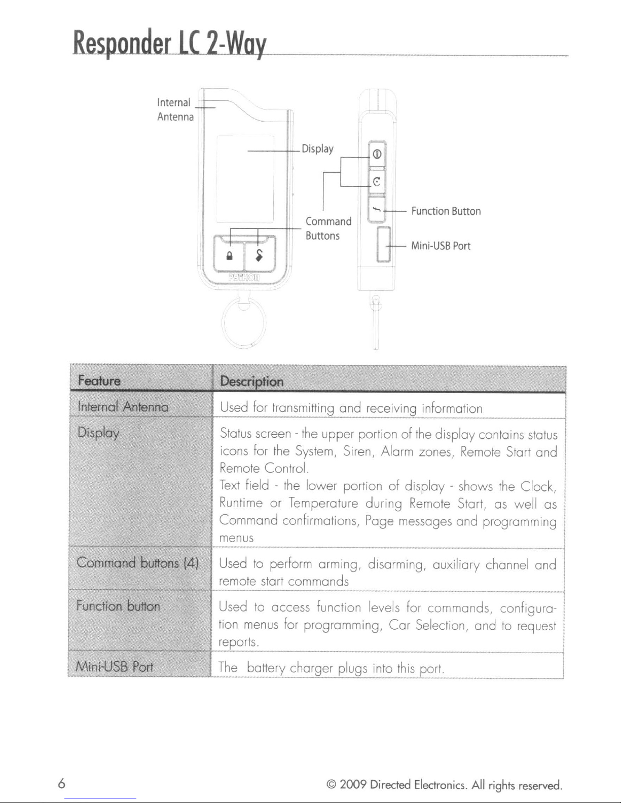
Feature
Internal Antenna
b-
Display
-
---
.--------r-----..,-
"
Description
Used for transmitting
Status screen - the
icons for the System, Siren, Alarm zones, Remote Start
Remote Control.
Display
~:--
Command
Buttons
and
upper
CD
Function
Mini-USB
~.
receiving information
portionofthe
Button
Port
display contains status
"
and
I
I
Text
field - the
Runtime
Command
~
Command
Function button Used to access function levels for commands, configura-
Mini-USB Port
buttons (4) Used to perform arming, disarming, aUXiliary channel
menus
remote start commands
tion menus for programming,
reports.
The
or
battery charger plugs into
lower
Temperature
confirmations, Page messages
portion
during
of
display - shows the Clock,
Remote Start, as well as
Car
Selection,
this
port.
and
programming
and
and
to request
6
©
2009
Directed
Electronics.
All
rights
reserved.
Page 10
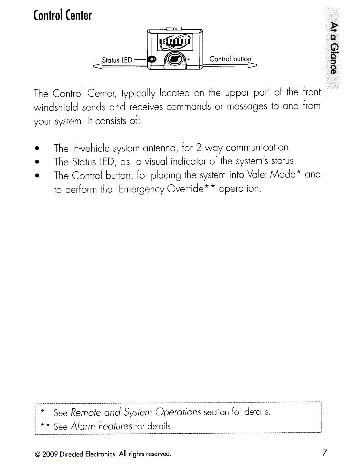
(ontrol
(enter
The
Status
LED
- .
IU--++-
Control Center, typically located
Control button
on
the
upper part
windshield sends and receives commands or messages
your system.
•
•
•
The
The
The
to
perform the Emergency Override** operation.
It
consists of:
In-vehicle
Status
LED,
system
as
antenna, for 2
a visual indicator of the system's
Control button, for placing the
way
system
communication.
into Valet
of
the front
to
and from
status.
Mode
* and
-.,,:-:;'·~::.;i·.?::'---·
;
'-.
~-
i'/.,~:~i
!~2
I* See
I * * See
L
© 2009
Remote
Alarm
Directed
and
Features
Electronics.
All
System
for details.
rights
reserved. 7
Operations section for details.
~,l
~
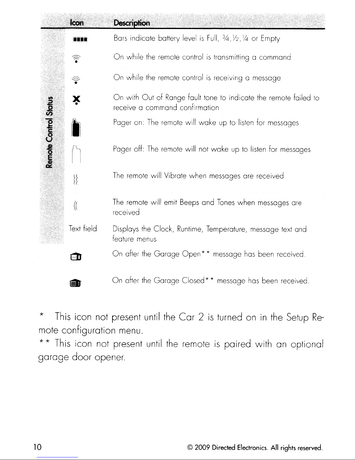
Page 11
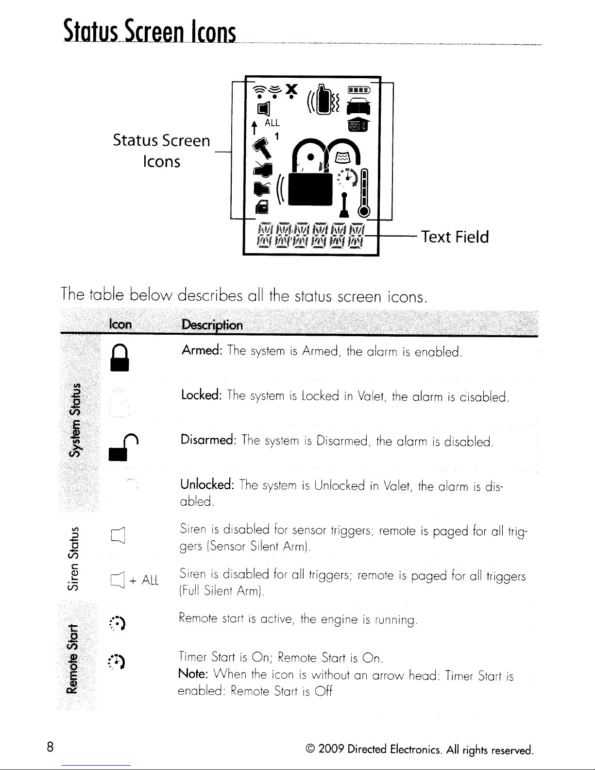
The
table
below
describes all the status screen Icons.
.2
.E
V')
V')
Vl
c
OJ
~
cJ
..
-)
..
Armed:
Locked:
Disarmed:
Unlocked:
abled.
Sirenisdisabled for sensor triggers; remoteispaged
gers (Sensor Silent Arm) .
+
ALL
Siren
(Full
Remote start
The systemisArmed, the alarmisenabled.
The systemisLockedinValet, the alarmisdisabled.
The
The systemisUnlockedinValet, the alarmisdis-
is
disabled
Silent Arm).
is
system
for all triggers; remoteispaged
active, the engineisrunning.
is
Disarmed, the alarmisdisabled.
for all triggers
for all trig-
.
~
-,
ir
I
Timer Start
Note: VVhen the icon
enabled:
8
is
On;
Remote StartisOn
is
without an
Remote StartisOff
© 2009
.
arrow
Directed
head: Timer Start
Electronics.
All
rights
is
reserved.
Page 12
..
,
:
~"
1
+
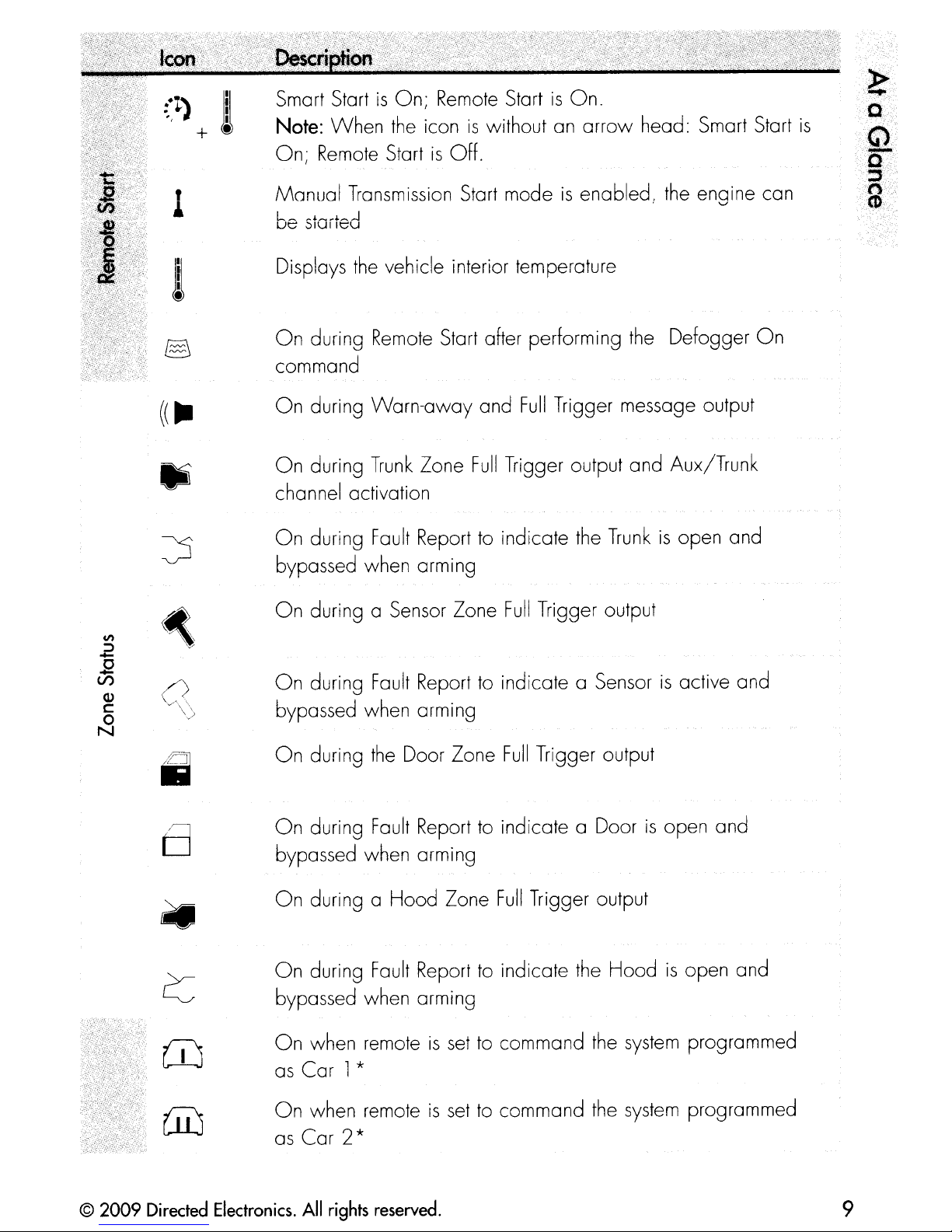
Smart StartisOn;
Note:
On;
Manual
When
Remote
the
StartisOff.
Transmission Start modeisenabled, the enaine can
Remote
iconiswithout an
StartisOn.
arrow
head: Smart Start
,
'-J
»
.....
Q'"
is
Q
Q
....
::L.
n···
CD
Displays
On
command
On
On
channel activation
On
bypassed when arming
On
On
bypassed when arming
the
vehicle interior temperature
during
during
during
during
during a Sensor Zone
during
Remote
Warn-away
Trunk
Fault
Fault
Start after performing
Zone
Report to indicate the
Report
the
Defogger
and
Full
Trigger message output
Full
Trigger output
Full
Trigger output
to
indicate a Sensorisactive and
and
Aux/Trunk
Trunkisopen and
On
On
during
On
during
bypassed when arming
On
during a
On
during
bypassed when arming
On
when remoteisset
as
Car
On
when remoteisset
as
Car
1*
2*
the
Door Zone
Fault
Report
Hood
Fault
Report
Zone
Full
Trigger output
to
indicate a Doorisopen and
Full
Trigger output
to
indicate
to command
to command the
the
Hoodisopen and
the
system
system
programmed
programmed
© 2009
Directed
Electronics.
All
rights
reserved.
9
Page 13
S'
~
x
Bars
indicate battery levelisFull,
On
while
the
remote controlistransmitting a command
M
3
I
V2,
1Mor Empty
•
On
while the remote controlisreceiving a message
•
On
with
OutofRange fault tone
•
receive a command confirmation
The
Pager on:
remote will
wake
to
indicate the remote failed
uptolisten for messages
to
•
('l
l I
((
Text
•
field
The
Pager off:
The
remote will Vibrate when messages are received
The
remote will emit Beeps
received
Displays the Clock,
feature menus
On
after
the
On
after the
remote will not
Runtime,
Garage
Garage
Open
Closed * * message has been received,
wake
and
Temperature, message
uptolisten for messages
Tones
when messages are
** message has been received,
text
and
*
This
icon not present until the
mote configuration menu.
**
This
go
rage
10
icon not present until
door
opener.
the
Car
remote
©
2009
2
is
turned on
IS
paired with an optional
Directed Electronics.
in
the Setup
All
rights reserved.
Re-
Page 14
llsing.~~._------
Commands
Commands, Basic or Advanced, are used
and
commands control the most often used security
tures
and
first by siren chirps and parking light flashes, and
and
feature confirmation
Advanced
are performed
while Advanced commands control more specialized features
request reports.
Confirmations for Basic or Advanced commands are indicated
beeps or tones on
Performing
and
command sections.
Confirmations
by
pressing one
the
is
found
Commands
to
activate
of
the
r'ommand
and
remote control. A description
in
the following Basic command and
system
buttons. Basic
remote start fea- "
then
by
features
Text,
of
Icons
each
Perform Basic commands
while
text field displays
vanced commands by first accessing one of the Function
then pressing one of
tion
in
the Direct Access level. Direct access
Levels
the
the
are available when the text field displays
by
pressing one
Clock, Temperature or Runtime. Perform Ad-
command buttons while within a level.
of
the command buttons
is
available while the
LEVEL
4.
Advanced command example: Silent Arm
1.
2.
Press
field will display
Press
Silent
the
the
Arm
f button once to access Function
~
button
command.
Levell,
},"10;.~~
while-~"'il;0
.
text
is
still
on
to
Levels
1,2,3
perform the
the
and
Func-
or
text
3.
© 2009
The
text field and update the
Directed
Responder
Electronics.
All
LC
rights
remote
reserved.
will
status
display
screen icons.
'i\x·
....
"
....
:;!£{
in
the
11
Page 15
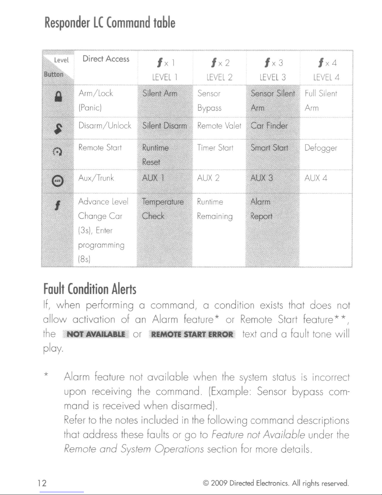
Responder
lC
Command
table
e
I
Direct Access
Arm/Lock
(Panic)
Disarm/Unlock
Remote
Aux/Trunk
Advance
Change Car
(3s),
Start
Level
Enter
Ixl
LEVEL
Silent
Silent
Runtime
Reset
AUX
Temperature
Check
1
Arm
Disarm
1
Ix2
LEVEL
Sensor
Bypass
Remote
Timer
AUX
Runtime
Remaining
Valet
Start
2
Ix3
2
LEVEL
Sensor
Arm
Cor Finder
Smart
AUX
Alarm
Report
Silent
Start
3
3
Ix4
LEVEL
Full
Silent
Arm
Defogger
AUX4
4
programming
(8s)
Fault
If,
allow
the
Condition
Alerts
when performing a command, a condition exists that does not
activation of an Alarm feature* or Remote Start feature **,
or ¥
LAlLI
or
REMOTE
START
ERROR
text
and
a fault tone will
play.
*
Alarm feature not
available
when
the
system
status
is
incorrect
upon receiving the command. (Example: Sensor bypass com-
is
mand
Refer
received when disarmed).
to the notes included
in
the
following command descriptions
that address these faults or
Remote
12
and System Operations section for more details.
go
to
Feature
© 2009 Directed
not
Available under
Electronics.
All
the
rights reserved.
Page 16
* * Remote Start feature not
available
when
the Remote Start status
is
incorrect upon receiving the
command
received
when
remote start
Refer to the notes included
dress these faults
r.
.
.)TarT
r.
leaTures
or
00
to
\..,/
" ( 1 ,
secTion
Tor
more oeTalls.
command.
in
the
command
Remote
Start
·1
(Example: Runtime reset
is
off)
descriptions that
Error
under the
Remote
ad-
A
."
'II
''''
. .
·'3·'·
.~
=
.
;,
os..
"CIt
..
..
.
.
© 2009
Directed
Electronics.
All
rights
reserved.
13
Page 17
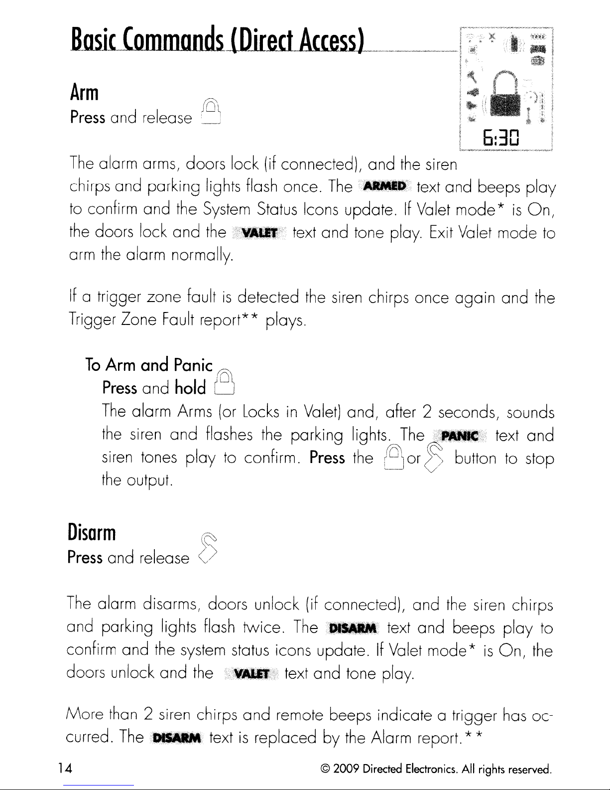
Arm
Press
a
nd
release
.~
._-r.~~··i'~
I:
I
1_._,..~
li)~i
6:30
...__.._.....
__
,>-
..
...".-.,..._,~
The
Trigger Zone Fault report** plays.
alarm arms, doors lock (if connected),
chirps and parking lights flash once.
to confirm
the doors lock
arm the alarm normally.
If
a trigger
To
Arm
Press
The alarm Arms (or Locks
the siren
and
zone
and
and
the System Status Icons update.
t
and
fault
Panic
hold
and
1
the x
1
.flle';' text
is
detected the siren chirps once
r01
1
U
in
Valet) and, after 2 seconds, sounds
flashes the parking lights. The
and
The"_~::
and
tone play. Exit Valet
the siren
text
If
Valet
and
!;~_*~
beeps
mode*is
mode
again
and
text
play
On,
to
the
and
siren tones play to confirm. Press the
the output.
Disarm
Press
The
and parking lights flash twice. The
confirm
doors unlock
More
curred.
and
alarm disarms, doors unlock (if connected), and the siren chirps
than 2 siren chirps
and
The
release
the system status icons update.IfValet
and
'1_:
~
()
the
~;;f;"""~"ii
and
text
is
text
remote beeps indicate a trigger has oc-
replaced
tll_X
and
by
Aor
text
tone play.
the Alarm report. * *
Dbutton to stop
and
beeps
mode*is
play
On,
to
the
14
©
2009
Directed Electronics.
All
rights reserved.
Page 18
AUX!Trunk
Press
The
onds.
Remote
Press
Activates (or if
parking lights
or
text and tones
The
Trunk
the
{:)
and
opens
The
Start
and
engine
icon will
hold
«~.I.s;
release
e
On,
turn
and
play
(if
connected) when
text
and
{:)
deactivates) the remote starter.
On
and
parking lights
to confirm, the Remote Start
display
tones
the
jj~:_#."4.~f;;
turn
in
the status screen
play
this
to
Off
button
confirm.
and
is
text
thef
status
and
pressed for 2
The
•••
the text field will
engine
and
tones play,
1'_~III:,t;
icons update.
sec-
and
display the Runtime, Temperature or
Start fails to activate,
while
***
the
parking lights flash to identify the reason. * * *
See
Remote
See
See
Alarm
Remote
Features
;;f~;_1If"~'.O';~ij*;
and
Start
System
for details.
Error
Operations for details.
(under
Clock
Remote
as
programmed.IfRemote
text
Start
and
Features)
a fault tone
for details. I
play
I
I
For
Manual transmission vehicles see Manual
~~mote
© 2009
S,-art
Directed
Features
Electronics.
All
section for more
rights reserved.
Transmission
det?~:~
__
.______
Start
in
the
I
I
15
Page 19
Press
and release
the
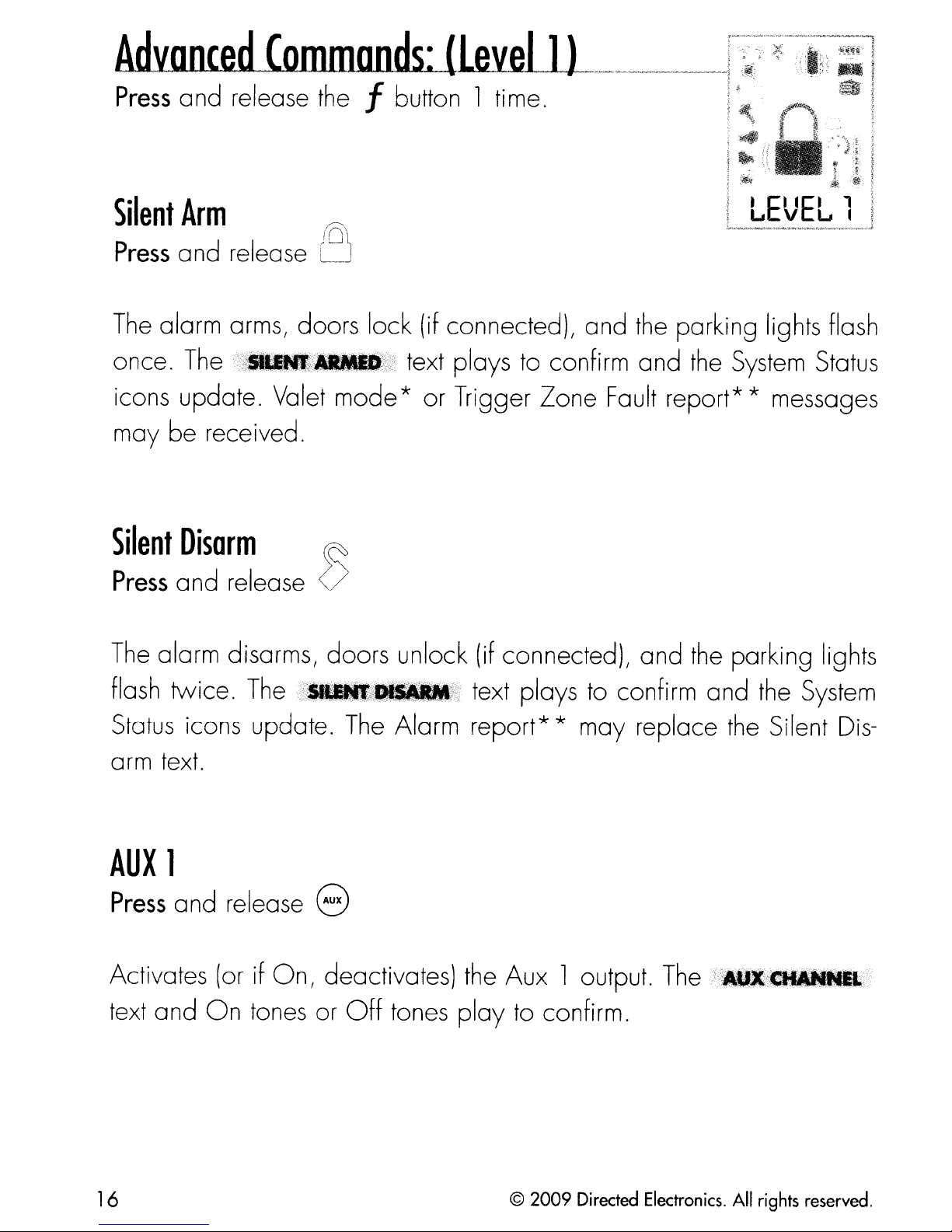
Silent
Press
The
once.
icons update. Valet
may be received.
Silent
Press
The alarm disarms, doors unlock (if connected), and the parking lights
Arm
and
alarm arms, doors lock (if connectedL and the parking lights flash
The
release
f%~
•••
Disarm
and release
rn
IU~
[/_.>0f
mode
~
()
text plays to confirm and the System Status
* or Trigger
Zone
Fault report* * messages
flash twice.
Status
arm text.
AUX
Press
Activates (or if
text and
icons update. The Alarm
1
and release e
On
The
tones or
in_m_f.~
On,
deactivates) the Aux 1 output.
Off
tones
text plays to confi
report*
play
* may replace the Silent
to confi
rm.
rm
and the System
The/:••
1
....
Dis-
t
16
© 2009
Directed
Electronics.
All
rights
reserved.
Page 20
Runtime
Reset
Press
If
will
!'~;3!_.';;;;U)
if
a
nd
more time
reset
set
to
display runtime.
release
is
the
text and tones play
~~:}
needed while remote start
runtime counter to the pre-programmed setting.
Note
Temp
Press
Request
a
nd
hold
the
f button
to
confirm.
is
active, runtime reset
The
text field will update
The
Requests
status
via
*
See
** See
the
vehicle's interior temperature and temporarily displays it
screen icon ! and text field.
Remote
Alarm
and
System
Features
Operations section for details.
for details.
© 2009
Directed
Electronics.
All
rights
reserved.
17
Page 21
AdvnncecLCommands:_.lLa'leJ
__
2J
-._
_.-
_-..-
_-
~
Press
Sensor
Press
The
the Sensor bypass type. 2 flashes indicates sensor
are
firm. 3 flashes indicates sensor
bypassed./;;
flash indicates sensor bypass
to confirm
and
release
the
f button 2 times.
Bypass
and
parking lights flash each time this
bypassed.llr.,;;"",?,
release
•••
..
.~.
._
';\".}"
1
Warn-away
1
beep
is
Off,III.MlI';.'
beep
and
command
and
and
2 fault tone play to confirm. 1
is
1 fault tone
Full
a
Ea
-Ea
....
v u '-
received to indicate
Warn-away
play
Trigger zones are
and 1
beep
;:I
zones
to
con-
play
Note
Remote
Press
Enters
On,
See
AUX
Press
Valet
and release
(or if
2 for Off)
Valet
2
and
(~
\
",~
<~'>
On,
exits) Valet
play
to confirm
Mode.
Mode for more details
release 8
TherMll\/\
and
the System Status icons update.
text
and
beeps
(1
for
Activates (or if
text and
18
On
On,
tones or
deactivates) the Aux 2 output.
Off
tones
play
to confi
© 2009
rm.
Directed
The
Electronics.
AtI.CIf
All
rights
..
M.t
reserved.
Page 22
Timer
Press
Start*
and release
.-)
~,.
Activates (or if
flash qUickly four times for
~w~l.'I
firm
and
•••
f.J!'>
the Remote start status icons update.
On,
or
deactivates) Timer Start. The parking lights
J
(0
5isi
••••
INote
I
'-'
~---
Runtime
Press
Remaining
and
hold
the f button
On
and
slowly four times for
WltMl';alp(4';i):
text
and
beeps
play
Off.
to
>~
The"§
con-I;)"
:;)1.""
"""~
Requests the remaining Remote start runtime
in
it
the text field.
Note
!
I * See Advanced
I
'--------_._--",.------_._
Start
under
...
_-------_.
Remote
__
Start
...
__
._-_._---_
and
temporarily displays
Features
..
for more details.
_
....
_._---_
.....
__
..
_._-_._._._._---"
©
2009
Directed Electronics.
All
rights reserved.
19
Page 23
Press
and release
the
f button 3
times.
Sensor
Press
The
times.
System
(or
Press
The
seconds.
Silent
and release 0
alarm arms, doors lock,
The.,__
finder
and release
siren emits one long chirp and
Arm*
=:-.e~~~_
and Siren
The
_i
Ii5i
Status
~
()
the
siren
text
and beeps play
icons update.
text and beeps play
chirps and parking lights
to
confirm and
the
parking lights flash for
to
confirm.
flash
The
3
the
10
parking light flashes stop if armed or disarmed while
progress.
AUX
Press
Activates
text and
3
and release 8
(orifOn,
On
tones or
deactivates)
Off
tones
the
play
Aux 3 output.
to
confirm.
The~)~("_f%gi
Car
Finder
is
in
20
©
2009
Directed Electronics.
All
rights reserved.
Page 24
Smart
Start**
Press
Activates (or if
flash qUickly five times for
~I%ll
firm and the
••
and
%f
••
release
!:III!~!;
Remote
{:}
On,
or
deactivates) Smart Start.
0!ill_fflllB~f.I!?f!
start
status
INote
L
Alarm
Reporf*
On
and slowly five times for Off.
icons update.
The
text and beeps play
parking lights
to
The
con-
Press
Requests
in
~e
I **
L .
and
a report of
the
text field.
Alarm
S~e
Advanced
hold
Features
the
The
f button
the
most recent triggers and temporarily displays
report clears when the ignition
for more details. i
Start
under
Remote
Start
Features
is
turned on.
for more details. I
.!
it
© 2009
Directed
Electronics.
All
rights
reserved.
21
Page 25

AcbLanretLCommands:l1eYeL4l-------.-,
Press
Full
Press
The
and release
Silent
Arm*
and release
alarm arms, doors lock, and
flash 4 times.
the
and
AUX
Press
System
4
and release 8
the
r;~
)
(\
l~
The;:
and Siren
......
f button 4 times.
the
siren chirps and parking lights
,)
..
Status
',,'
text and beeps
icons update.
LEVEL
ploy
to confirm
l.f
Activates (or if
text a
nd
On
On,
deactivates)
tones or
Off
tones play
the
Defogger**
Press
Activates the vehicle Defogger circuit
is
Remote
cuit will also automatically activate
the
and release
activated.
Start
temperature
The
status
is
{:)
,':.'-i'QN;
icons update.
below
55°F.
text and beeps
For
Aux 4 output.
to
confi
(if
connected) while Remote Start
rm.
ploy
convenience,
The:R811.%I_&~
to
confirm and
the
Defogger cir-
the
10 seconds after remote starting if
Note
~--:-~See
. * *
; dealer. !
; .•.
,."~..~.
__
22
This
w_.
__~,,.__..
Alarm
feature
__
~_._.
__.., .
Feo~ur~-;f~~-;;;~redeta~---------------'
must
.w
•••~••
be installed
~._.~~_._"._.
__w.•••
,~....
and
.,.~,,
__.'__'__
turned
"~'.~.''''''''_~__~~''·~
©
2009
on
by
an authorized Directed i
'
Directed Electronics,
·_'~_~_''''_.
__
'W·__.,,..._.
__
.w,~~__~_..--._..~_._•.~_~__~-l
All
rights reserved.
--
I
Page 26

Operations of
set
in
are
the
the
Responder
configuration
LC
Main
and
Menu.
howitcommunicates messages
Navigating
Navigating
performed using
discuss
Button
•
•
•
Access
1.
To
displayed
To
To
menu
Press
menus
menus
how
to
operation
access
scroll
exit
the menu
configuration:
items
and
and
the
access and configure
menus,
in
the
hold
options
and features, changing options, and exiting are
remote control buttons.
set
options, and to
text field,
lists
use
the
f button for 8 seconds,
in
the text
the
use
~
The
following instructions
the
settings.
perform
the f button.
fiel~se
or
()
the
buttons.
the
8&
actions that are
(~
remote will beep
buttons.
2.
3.
once,
Select text and beep after 3 seconds).
Release
_~
The
Use
tions and settings
monly
•
•
~;~_t.I.~
the
...
Main
the
following process to
used
Press
is
that
Press
view
is
in
the
f button to display the
'isdisplayed.
Menu
throughout
the
80r
displayed
the
f button
its
options.
text field to
is
displayed.
has
been accessed and configuring can begin.
view
in
the text field.
the
configuration operation,
{:)
buttons to change
in
the
text field.
to
choose
Pressitwhen the desired feature or option
set
it as
(If
The
the
the
Car
the
2
is
on, ignore
Main
Main
following actions are com-
feature
new
setti
Menu
Menu features, op-
the
feature or option
in
the
text
ng.
the
Car
item
field and
list,
© 2009
Directed
Electronics.
All
rights
reserved.
23
Page 27

The
of
the
following
remote control,
Main
Menu
list
of
features
-----_
is
available for configuration
..
_---_
..
_----.-
Setup
Remote
Keypad
Options:""',"'ltJII'
When~ir.JII;,
mand when pressed.
lock after a
unintentional operations.
fault tone plays
text field.
To
button.
field, a command can
menu:
Lock
the
buttons
20
second lapse between buttons presses
as
an alert followed by unlock instructions
unlock the buttons,
The
unlock tones play and ';f:,..,,;t£
do
When
If
press
now
not lock and always perform a com-
set
to._~,
a button
the
be performed.
f button followed
is
pressed when locked a
the
is
displayed
remote buttons
to
prevent
in
the
by
the
in
the
:8
text
Auto
After turning
lock
Unlocking
authorized Directed Dealer.
Page
Options:;_:""",·:Glfi,f;'.;.
Paging
messages.i_;X
24
unlocking
the
the
keypad buttons
is
not desired
Mode
is
how
ignition off, a message
the
next command
the
Responder
••
this
> extends battery life by turning Paging
message can be turned off by an
LC
remote monitors your
©
2009
to
the
remote will
is
performed.
Directed Electronics.
If
system's
All
rights reserved.
un-
Auto
Page 28

Off
after
72
hours if the remote control
is
not used during
this
period.
set
from
remote start or alarm trigger pages.
Note:
is
performed but alarm trigger pages will not be received.
Page
Options:
There are several ways for
has
Just
press any button to
to
\;;11111
the
When
it wakes up every few seconds
system.
When
«,,..t
set
to
iWIIII$fi
responses are
Alert
\fu"I;;"f;~,~_~,v;"1-fj,~_"'wl
the
Responder
received a message from the
resume
it
does not
still
system.
system
received when a command
LC
monitoring.
to
listen for pages
wake
to
up
alert you when
When
to
receive
it
%1111',..,\
mote. Select r%_:J
each message. Select
alert you with a gentle vibration, or select
don't want to be interrupted.
The
text field can be
ing remote start.
interior Temperature, or the
field while
will alert
r;~_!j:J:
Remote
by
both emitting tones and vibrating the
to
be alerted
tt_t,;~
set
to display
Remote
Start
is
on.
and
~_
by
tones that are unique for
the
Responder
the
information you prefer durStart
will be displayed
LC
t,RI.::_i$
Runtime,
l:l_:jj:
re-
will silently
when you
vehicle
in
the
text
© 2009
Directed
Electronics.
All
rights
reserved.
25
Page 29

Runtime
Alert
Options:»8N,
The
about
the
alert output
(ar
Options:
This
the remote can be
main unit will send a
to
expire.
Remote
2
OFf,
remote can control
••
t>,
the
Car2
••
When
Start Time-out message
is
emitted for the message.
ON I
select option
'
page
set
tOI)N1
HOME
two
set
to control 2 systems.
to
systems
is
not available.
alert you when the runtime
an alert
is
received.
independently.
is
generated when
When
When
When
The
•••
set
, option
).,..
tot.
I no
set
is
to
is
for pairing to a home security system.
Screen
opti0 ns: OfF I
The
with a selected color during output when
colors.
Temp
Options:.,
Temperature can be displayed
Color
status
Unit
WHITEI1T
screen backlighting can
GIN,
VIOI.ET,AQUA
C
In
be
your choice
,RID
sIMI
set
I or
to
one
,GUIN,
will
of
illuminate
of
the
temperature
aWl
option
scales, Fahrenheit or Celsius.
26
© 2009
Directed
Electronics.
All
rights
reserved.
Page 30

Buffon
Beep
opti0
When
of
button presses.
System
Options:
Selects the type
Entry to
and
for your system.
ns:
;i";":,..,
set to):Mt:, the remote will emit a
a button press.
Type
·:?tllC;;~'
which
main menu accordingly.
,Y.:'
,~':,.);::;.
When
of
system, namely; Security
the remote has been paired,
set
to
:,.~:,
This
has been pre-set
beeps are not emitted for
beep
or
and
as confirmation
Remote Keyless
adjusts the text
by
the factory
'n'
.'
,
.,
..
o
:~
c:6~:
.e·
Clock
options:
Set
:1.;_;%,1;.'"J
Review
Displays firmware version
Exit
Exits
Sensor
If
you feel your security
sensitive enough, it
and
returns to the main menu
Adiust:
system
is
highly recommended that you contact your au-
shock sensor
is
too sensitive
or
not
'a'
..
0-····
•.'",
',,'<;:-'
"::J .
"CIt
.
thorized Directed
for
optimized
© 2009
Directed
security detection performance.
Electronics.
dealer/professional
All
rights
reserved.
and
have the sensor adjusted
27
Page 31

Pair
Remote:
Remote Pair
the
vehicle learn each others encrypted identification, securing their
communication from intruders. Please note that your remote controls
come pre-programmed from
Prepare
1. Open at least one
2.
3.
4.
the
Turn
Within
the Control Center.
Within
LED
system
is
a process where the Responder
the
vehicle
the
key
5 seconds
5 seconds,
will flash one time and
is
ready for remote pairing.
systemtobe
of
the vehicle's doors.
to
the
On
press
press
position.
and release 1 time the Control button on
factory.
Paired
and
the
with
hold
siren will chirp
the Control button.
a new
LC
and
remote
once
the
system
The
to
confirm the
in
status
5.
Note:
and the siren will chirp.
Prepare
1.
2. Perform
3.
4.
Release
If
pairing does not
the
Make
2 operation.
Pair Remote mode.
When
remote
Press
the remote will emit several tones to confirm successful pair-
the
Control button
new
sure
the
the remote beeps 3 times
is
and
remote
the remote control
steps
ready
to
hold
and
result
to
under Access menu items section to access the
pair.
the
eJ
within
be
Paired
button, the siren will chirp once
proceed below.
60
seconds, the
is
with
set
the
system
for the desired
and
fi_~f#
system
Car
is
displayed the
will exit
1or
Cor
and
ing.
menu.
Note:
mode
try
again.
28
~:!_~
~~~'Il
in
case
will be displayed and
of
an unsuccessful pairing. Check the
is
displayed
and
© 2009
the
remote returns
the
remote will stay
Directed
system
Electronics.
All
to
in
status
rights
the
the
main
pair
and
reserved.
Page 32

Demo
mode:
Demo
stration tool to show friends or family. Running Demo mode shortens
the battery life over time if used excessively
•
•
•
•
Mode
:i~._.fIfAf;~:::
status
the
~I
•••
status
the
%~{l;j'''I
status
the
the battery charger
~1l_i_.·'g:
status
the
battery charger
plays a pre-selected
The
screen without beeps and tones then stop
t".}i:
screen with beeps and tones then stop
•••
screen without beeps
screen with beeps and tones
tj;J;r
The
The
The
is
remote vlill display a selection of icons on
remote will display a selection of icons on
remote will display a selection
is
disconnected.
remote will display a selection of icons on
disconnected.
group
and
of
animations
tones
in
an endless loop until
as
a demon-
of
icons on
in
on endless loop until
the
Note: Loop Silent and Loop Sound are not
appear
nected.
Power
When
power
_~.,{~
off
tones play,
To
turn
status
the
also
connected.
in
the Demo
Mode
menu unless
Off:
an extended period of non-operation
off will preserve
is
displayed.
the
the remote on,
screen icons refresh as
turns
itself on and begins charging when the battery charger
remote
the
battery charge.
The
Press
status
is
turned off.
and
the
screen icons clear
hold
power
the
the f button for 3 seconds,
on tones play.
available
battery charger
is
anticipated, turning
Press
the f button while
and will not
as
the
The
is
con-
the
power
remote
is
Exit:
To
return to normal operation,
played
© 2009
Directed
Electronics.
All
rights
reserved.
press
the f button while
EXIT
is
dis-
29
Page 33

Normal
Arm
Protection
Status
that your vehicleJs security
Starter
starting
LED:
Kill:
The
Control Center Status
system
The Failsafe starter kill relay prevents the engine from
is
active.
LED
flashes as a visual indicator
Note
Sensor
pacts from major impacts to the vehicle exterior.
the system to emit a
flashing the parking lights for 3 seconds.
example
The
triggers:
by
a forcible entry attempt,
siren sounds
The
and
onboard
Warn-away
the parking lights flash for
shock sensor can distinguish minor
output
by
Major
results
Minor
chirping the siren and
impacts caused for
in
a
30
impacts causes
Full
Trigger output.
seconds or longer.
im-
Both
control.
Point
ger output,
the siren to chirp 3 seconds before beginning the
This
case
remote.
Sensor
Sensor
sages to the remote,
Warn-away
of entry
3 second
of
accidental trigger.
Silent
Warn-away
triggers:
while
Arm
and
opening
delay
Full
Opening
allows
protection
and
Sensor
while
Triggers send a message to the remote
the hood or trunk causes a
a Door
time to disarm
The
the parking light flash
or
turning on the Ignition causes the
Full
Trigger message
Full
Trigger activations
and
Full
Full
Trigger output.
silence the siren
is
still sent to the
and
only
siren outputs are
send
Trig-
in
mes-
defeated. Point
siren,
30
and
send messages normally.
of
entry triggers will activate the parking light flash,
© 2009
Directed
Electronics.
All
rights
reserved.
Page 34

Full
Silent
Arm
Protection
Sensor Warn-away, Sensor
will only send messages
si
ren
outputs defeated.
Sensor
When
10
text for
displayed
Full
A
Full
and zone specific
Warn-away
the
remote receives a Sensor
beeps
Trigger
Trigger message generates a
(if
on)
30
seconds.
in
reports.
Messages
Messages
and
,;i~~_!¥~\
to
displays a sensor zone
Warn-away
Full
Trigger and Point of Entry activations
the
remotelwith parking light flash and
Warn-away
specific~._."':
messages cannot be reviewed or
Full
Trigger output of siren tones
text followed by an alert that consists
message
it
emits
of
1 long
To
stop the output
command
Emergency
The
mote
beep
per minute for
or
l
Press
Override
following procedure disarms
is
not available.
1.
2.
3. After a
Turn
Press
number of times
is
disarmed.
10
minutes.
and
the ignition
the control button on
few
alert,
the
f button.
Number
seconds the siren output ceases and the system
On.
(the
press
of presses _
default
a command button to perform a
the
system
the
is
when a programmed
Control Center the correct
1
press).
re-
Note
© 2009
Directed
Electronics.
All
rights
reserved.
31
Page 35

Trigger
Zone
Fault
Report
When
of
the
light
center
and are monitored
correct (dome light
normally.
The
chirps
indicate
play zone specific text that identifies the faulty zones.
Alarm
armed by remote command the
alarm trigger zones. Faulty zones (usually caused by dome
delay
siren chirps once again a
as
Report
or open
LED
and remote,
turns
an audible alert,
the
zone number.
when
disarming
trunk)
to
protect
are bypassed and reported via
'vvhile
off)
the
The
all other trigger zones remain active
the
vehicle. Should a faulty zone self
it
becomes active and
few
control center
remote will emit a single fault tone and
system
seconds following
LED
runs
flashes
is
a
status
then
check
the
control
monitored
the
arming
in
groups to
The
disarmed via
center
the
groups
of Zones).
identifying
most
parking lights flash 3 times, and the control center
recent alarm triggers (if any) are reported when
the
remote control, siren chirps, parking light and control
LED
flashes.
to
indicate
Theifi0
the
The
the
i
;%r_Wi
triggers.
siren chirps 4 times (or 5 times if
last two zones that were triggered
wc
text
is
replaced
by!!~".111_;!
the
NPC
LED
alarm
On
flashes
(see
and text
is
*),
in
Table
! * See Nuisance
!
32
Prevention
(NPC)
for more details.
© 2009
Directed
Electronics.
All
rights
reserved.
Page 36

Trunk
2 Shock Sensor
3
4
5 Ignition
6
Alarm
The
ing on
will display text to identify
hicle
identify the
Report
Alarm Report displays the two most recent alarm triggers depend-
the
was
when
system state when requested.
last driven.
two
requested
When
most recent triggers since
r
i Note
:
Door
Sensor 2
Hood
When
the
two most recent triggers since the
armed, the report will display text to
the
disarmed, the report
system
was
armed.
ve-
Nuisance
NPC
bypasses them until corrected.
is
left open following a forced entry,
again
Bypassed sensors automatically
vehicle
bypassed sensors.
©
2009
Prevention
monitors all alarm zones and, if
only after being closed.
is
driven. Disarming
Directed Electronics.
(NPC)
All
rights reserved.
If
then
any
a point
it
is
reset
re-arming
are triggered excessively,
of
entry
bypassed.
after one hour and after the
the
(trunk,
It
alarm does not reset
hood, door)
becomes active
33
Page 37

Pit
Stop
To
exit vehicle with engine running
Mode
The
or convenience store.
3. Turn the key to off, and remove it from the ignition, the engine
4.
I-
I
I
'-----
1.
2.
Note
system
With
foot brake.
Press
~_ilflll~.Iiil{
continues running for the programmed runtime.
Exit the vehicle
keeps the engine running during short trips into the house
To
perform
the engine running! set
the
(:)
button, the parking lights will
message
and
arm
Pit
Stop:
the
parking brake
wiIIplay
the alarm.
on the remote control.
and
turn
release the
on
and
the
Key
Takeover
When
The
driven.
1.
2. Insert the
3. The parking lights
34 © 2009 Directed
you
are
ready
system
Disarm the system and enter the vehicle,
brake.
brake, the remote start then
keeps the engine running until the vehicle
To
perform Key Takeover:
key,
to drive
turn it to the
turn
off to indicate remote start
run
turns
position,
off.
do
and
is
ready to be
not step on
then step on the foot
Electronics.
All
is
rights
the
off,
reserved.
foot
and
Page 38

then after a
message.
few
seconds the remote plays
the_.1:"~0"
4.
Remote
Remote start safe-lock makes sure the doors are locked while the
gine
is
Disabling
Remote start can be disabled
position.Ifremote startisattempted while
(See
back
The vehicle
Start
is
running and after, even if they are unlocked when remote start
activated. Door locks may require additional parts and labor.
Remote
Remote
to the
On
is
ready to drive.
Safe-lock
Start
by
moving the Toggle Switch to the
Off,
Start
Error
position to resume normal operation.
under
Remote
Start
the engine will not start.
Features)
move the switch
en-
Off
Advanced
The
cally start the engine to maintain battery charge or combat extreme
cold when parked for an extended period
Advanced
Precautions for the Advanced Start features:
• Park
and
• Arm and
doors are locked.
•
•
Only
time.
For
Start
start features Timer Start
the
vehicle
doors that lead into inhabited spaces.
Lock
one Advanced start feature can be enabled at
manual transmission vehicles MTS mode
in
a well ventilated area
the vehicle, the engine will not start
and
Smart Start will automati-
of
time.
away
must
from
windows
unless
any
be enabled
the
given
beforeTimer
© 2009
Directed
Electronics.
Startor
All
SmartStartcan be activated.
rights
reserved.
35
Page 39

Timer
Start
operation
Activation begins a countdown timer
fault 3 hours).
__
Remote
messageissent
This
Timer Start
Smart
Smart Start
and battery level
the
perature and battery level
start runtime expires the engine
will repeat as many times as
is
Start
uses
countdown timer.
When
~.J
exited after the final start.
message
to
the remote control and
the timer expires
is
sent
set
operation
the settings for Timer Start
to
automatically start
When
the timer expires the vehicle interior
is
checked and, if the Temperature
to
by
as
set
by
the installer (de-
the
engine
the
remote control.
shuts
the
off,
the
the
countdown timer restarts.
the installer (default 6 starts).
in
addition
engine. Activation begins
starts
_111-..
to
temperature
and the
When
is
above
the
tem-
lOaF,
start and the
controls.
the
countdown timer restarts. Smart Start
below
When
f_.~1I1
OF,
or
__
the Remote start runtime expires
the battery level
.-Ml
message
..
? message will be sent to
is
sent to
is
/Note
I
Temperature
During Remote start the vehicle interior
perature changes.
Reporting
If
a change
in
temperature
is
below
the
exited after the final start.
is
checked regularly for
1O.5v, the engine will
the
the
engine
remote control
is
detected
this
remote
shuts
and
report
off,
the
tem-
will be
this
information
36
sent
report
to
the remote for display. Each time the remote receives
it
will beep, update, and display
usi
ng the Temperature
Gauge
© 2009
the
icon.
Directed
newest temperature
Electronics.
All
rights
reserved.
Page 40

, Note
Remote
During remote start a message
at one minute before
with tones as an alert to reset the runtime if desired.
Manual
When
that
properly
t
t
sar e engine on
on alert.
1.
Start
Transmission
installed into a manual transmission vehicle,
the
MTS mode
set
th
With
TIme-out
or
is
defeated after being properly
. d
the engine running, set the parking brake and leave the
Alert
the
engine
Start
is
properly
th
'·.·.'I.:.·
e/~~.:
is
turns
(MTS
set
.•.
~.·
•.
·lt1
..
,'-:
sent three minutes before
off.
The;'I_'la\9<
mode)
when parking.
•..
·._.·.:.'.~l
t_;-,:,J~,-_'.,,!c<
•.
.-;:j_.'.-.·..·.-
If
set
·."T
...
··.·
...
t t d t I
ex on ones
and
the
system
MTS mode
the
system
again
text plays
requires
is
not
wiIInot
pay
as
2.
3.
4.
engine running.
engine running aher arming) open the driver door.
Release
release
there
Within
button on the remote, after
Timer
or send the Timer
screen).
The
parking lights flash 5 times to confirm MTS mode enable
the
remote start activates
text and beeps ploy to confi
the foot broke (if pressed during Step 1Lor
the foot broke anytime.
is
no time limit to perform
20
seconds
Mode,
For
Pit
Stop or Turbo Timer mode
As
long as
this
step.
of
foot brake release,
20
seconds
press the optional dash mounted activation button
Mode
command from
the
ignition outputs.
rm.
returnto
the
engine
press
the
Advanced Start menu
The;
any command
Step 2
.....
(to
leave the
press
is
(For
~~sr
and
running
Turbo
and
..
;....J
,~.i
-\
5.
©
Turn
remains running.
2009
Off
. .
Directed Electronics.
and
remove
All
the key from
rights reserved.
the
ignition switch, the engine
37
Page 41

6.
Exit
the
veh
icle,
close
aIIthe doors a
nd
arm the
system.
7.
Turbo
The
can be activated by remote control or optional dash mounted activation button.
1.
2.
3.
The
engine
message plays to confi
the
engine continues to
Timer
system
With
Press
Timer
The
tion outputs.
keeps
the
the
Mode
parking lights
turns
off
and
Mode
the
engine running for the
engine running,
optional dash mounted activation button or perform
command.
turn
The
~,""""'t.ii
after a few seconds,
rm.
If
the
run.
set
on and
door
the parking brake.
the
remote start activates the igni-
is
text and beeps play to con-
the~__
opened
Turbo
.Bi
inStep
Timer runtime and
3
then
the
firm.
4.
5.
6.
Turn
remains running.
Exit
The
r-:--'-'
INote
I
Off
and
. .
the
vehicle,
engine
remove
runs
the
key from the ignition switch, the engine
close
for the Turbo
all
the
doors and arm the
Mode
runtime.
system.
38
© 2009
Directed
Electronics.
All
rights
reserved.
Page 42

Remote
For
user safety, the system
Start
Error
must
be properly configured or remote start
will not activate. Refer to the table
below
for the screens
light flashes that will identify the configuration issue
5
6
7
8
None
Brake on
Hood
After performing Remote Start
command - MTS not enabled
After performing Timer Start or
Smart Start command
Toggle Switch
Alarmistriggered
open
off
Release foot brake
Close hood
Enable
Check all Solutions
Turn
Disarm or reset alarm
MTS
switch on
and
mode
and
parking
resolution.
*
Refers
to the number
of
parking light flashes.
©
2009
Directed Electronics.
All
rights reserved.
39
Page 43

Possive
Arming*
Park
ing
seconds the siren
itself.
open the trunk to load or unload items and, after closing passive arm-
Ing
door
locks the doors.
Auto
Auto re-arm ensures the vehicle stays protected ifitis
and
countdown
Anytime before
resu
To
exit
the
begins.
mes.
stay secure
is
not opened within
Re-orming*
vehicle, after the doors are closed the
The
led
then
the
in
flashes
chirps once. At
system
case of occidental disarming
30
arms you can re-enter
seconds the
qUickly and upon reaching 20
30
seconds the
the
system
re-arms
not entered aher
Passive
system
the
vehicle or
system,
itself and
arm-
arms
if a
disarming
automatically
30
seconds.
disarm
Onetime
Turn
chirps once to confirm one-time bypass
One-time bypass can be used to temporarily bypass
ing operation for one cycle.
auxiliary channel outputs programmed to activate when arming. After
the next disarm all operations return to normal.
the ignition
by
remote control. After disarming
re-arms
Open
by
remote.
Byposs*
itself (and locks the doors if programmed on)
any point of entry to stop the
On
for one to three seconds
is
It
also bypasses the comfort closure and
by
and
enabled.
remote,
re-arm
then Off.
until the next
the
the
The
Passive
alarm
in
siren
arm-
I:
*
These
40
featur~s
must
be
turned
an
by
an authorized Directed dealer ]
© 2009
Directed
Electronics.
All
rights
reserved.
Page 44

Valet
Mode
Valet mode can
command or manually using the vehicle key and the control button.
When
nience features still operate normally.
Arm
I~_~~
Use the following steps to manually enter
1.
2. Immediately press and release the control button once
3.
entered, the alarm functions are defeated
and
Turn
The
exiting.
Disarm commands lock and unlock the doors
text and beeps play
the ignition switch
control center
be
entered and exited
to
On
LED
turns
by
confi
and then
On
rm.
when entering and
performing the Remote Valet
and
Off
while
exit Valet
the conve-
while
Mode:
Off
the
when
Power
To
its
flashing
will
Rapid
If
power
resume the state it was
is
reconnected.
Automatic
The system sends a silent message to all remote controls after any
Save
reduce
output if the vehicle
turn
power
is
reduced after
off 1 hour and will
consumption
Resume
is
ever disconnected by a mechanic or thief, the
Remote
Updates
the
control center status
is
parked for an extended period.IfArmed the
24
hours.
reset
in
at the time
When
each time the ignition
of
Valet mode
disconnection, when
LED
is
is
modifies
On
the
turned off.
system
power
LED
will
major action has occurred.
updates the status screen icons.
review the
©
2009
Directed Electronics.
system
status
All
When
just
by
accessing the
rights reserved.
the
This
remote receives
way
all
users
status
this
are
able
screen.
message
to quickly
it
41
Page 45

OutofRange
Each time a command
mand confirmation from
received the out-of-range icon (
is
performed the remote will expect a com-
the
system.
If
a command confirmation
~
) and a fault tone will
alert.
No
Remote
Occasionally
generate a command confirmation output
This
indicates that
Output
when a command
the
system
is
performed the remote may not
or
Out
of
Range output.
received the command but
incomplete command (e.g. Aux button pressed too short
the
trunk release) or it was an illegal message (e.g.
was
mal functions
corrupted
due
of
the
to
local
system
RF
interference). These are temporary nor-
and remote, perform the command
the
is
playas
it
was an
to
activate
command
again
not
an
within
Feature
The'i1
10
seconds
not
i
n.'",V.I'
and solution
Runtime
Sensor
Defroster
Reset
BYf.?ass
to
return
Available
••
depending
;:f"
message
Remote Start
Systemisnot armed
Remote Start
Not
configured for
this.
to
upon
is
Off
is
Off.
normal operation.
is
a generic one which varies
the
command used:
Only
Only
Only
Only
Defroster control.
available
available
available
available
when Remote StartisOn
when
when Remote StartisOn.
when configured for
systemisarmed
in
cause
42
©
2009
Directed
Electronics.
All
rights
reserved.
Page 46

~
Q
LED
Level
Button
Q
.~.~
" .
",
Di
rect
Access
Arm/Lock
(Panic)
Disarm/
Unlock
Remote
Start
Ixl
LEVEl
Silent
Silent
Runtime
Reset
Arm
Disarm
~
t:)
e
f
PVIIIOII
1
Command
l-
Buttons
Function
Button
Ix2
LEVEL
Sensor
Bypass
RemoteValet
Timer
2
Start
Ix3
LEVEl
Sensor
Arm
Car
Finder
Smart
3
Silent
Start
Ix4
LEVEL
Full
Silent
Arm
Defogger
4
e
I
Aux/Trunk
Not
Used
AUX
1
Usedtoaccess
(I
with
multiplierintop
AUX
2
function
AUX
levels
for
row implies
3
Advanced
button
AUX
4
Commands
presses)
~
I
~
'<
©
2009
Directed Electronics.
All
rights reserved.
43
Page 47

Using
the1way
companion
remote
The
shown
Responder
to
scribed
Accessing
Similar
when a command button
Commands
els, f
LED
the desired command button while
companion 1
in
the
previous table, but without
LC
remote. Siren chirps and parking light flashes are used
indicate that a command
in
the
Basic
way
and Advanced command sections.
remote commands
Commands
to
x4
flashes
the Responder
press
in
the
in
the
table for example implies pressing f 4 times.
groups for a few seconds to indicate
LC
f button 1
has
been received and activated
remote, Basic commands are performed
is
pressed directly.
to
4 times
the
the
system
the
message display
To
perform Advanced
to
access function
LEDisflashing
features as
the
level.
to
perform the
of
as
de-
lev-
The
Press
the
command.
Buffon
When
lapses between button presses.
fault tone
by
Car
Car
gramming section
3 seconds.
indicate
Auto
On,
the
0 button,
Select
2
must
the
lock
the remote control buttons lock if more than
is
emitted.
first be turned
The
selected
To
unlock
the
buttons unlock and tones play to confirm.
On
below
remote flashes
Car
to
turn
is
1 or 2, release
If
the
(See
on).
the
a button
buttons;
Remote
Press
LED
20
seconds
is
pressed when locked, a
press
and
and beeps once or twice
the f button followed
Features
hold
the
button for
menu
the f button for
under
Car
Select
Pro-
to
or continue
Release
beeps continue to perform
mand can be performed
44
to
hold
the f button,
for programming.
then
Car
by
press
Select.
pressing one of
and release while
Once
© 2009
the
the
Directed
carisselected a com-
command buttons.
Electronics.
All
the
rights
LED
reserved.
and
Page 48

Programming
To
enter;
hold
the f button for 8 seconds, the remote emits
one
long
beep
accessed.
To
1 short
off
and
exit;
when
press
and
Sensor
The Bbutton
alarm triggers, it
dealer
Remote
Press
turns the
and
1 long
programming
LED
on, the
programming
release the f button to
beep
is
is
exited.
emitted for
Adjust
is
used for sensor adjustment, to
is
recommenced that an authorized Directed
perform all sensor adjustments.
Features
and
release the
menu
:[)
button, 2
go
each
LED
main menu has been
back
step
flashes
and
back,
avoid
and
repeat to exit.
the
LED
unintended
beeps
turns
indicate the remote features menu
buttons
beeps
• Autolock feature:
• Remote Beeps:
•
Remote
Press
is
ready
Per
of
this gUide,
be
indicated
and
Car
flashes turns the feature off.
2 feature:
Learning
the
:~:}
button, 3
to
program
the instruction
following
Paired
with
below,1beep
Press
Press
Press
LED
to the system.
in
Remote
a new
:[)
{:}
flashes
step 4
remote.
is
accessed
and
flash turns the feature
and
Bto turn on/off.
to turn onloff
to turn on/off.
and
Pair
of
Press
beeps indicates the remote
under the
Prepare
and
Main
the
hold
can
be
set.
Menu section
vehicle
the
~stem
LJ
Press
on,
to
button,
2
the siren emits
learned.
©
2009
Directed Electronics.
one
All
long
rights reserved.
chirp to confirm the remote has been
45
Page 49

Baftery
Information
(l-Way)
The1way
battery
normal
Battery
G)
(PN
use.
Replacement
RearView
~
11-W"'V)
~
=
=
Battery
Cover
companion remote
is
powered
by
one 3V coin cell lithium
CR-2032) that will last approximately one year under
1.
CD
11-lA!Ifllvl
Battery
Clip
Slide
plying equal pressure at
bottom
cates
from
2. Gently pry up on
move
the
battery cover up
(the
the
the
arrow
on
the
direction), remove
remote control housing.
the
it
from
the
holder. Insert a
by
its
top and
cover indi-
the
cover
battery to
ap-
re-
new
clip with
the
mote control
positive
is
now
(+1
side up. Replace
ready for
battery into
use.
the
holder and under the
the
battery cover.
The
re-
46
© 2009
Directed
Electronics.
All
rights
reserved.
Page 50

S¥sJemlxpau..u.v..u~w..LI.JL.......
__
-------_._--_._-_
..
_-_._-_
..
__
.
__.._._--_
.._.....
Controlling two vehicles
The
in
This
vehicle that has more than one driver. See Owner Recognition follow-
ing for details.
Owner
The
disarming and
preferences.
remote button auto unlocking, alarm output duration can all be custom
set
Responder
two
different vehicles saving the need for multiple remote controls.
feature also allows for customized
recognition
system
for each remote
LC
and 1
can be configured
change
Memory
user
(Car
way
selected features to match the remote
seat adjustment, siren chirps, passive arming,
at the time
Select)
companion remote can control systems
system
to
recognize the remote used when
of
installation.
configurations on each
users
Comfort closure
Comfort Closure emulates turning the key
ing
the
lock button
the
windows
nience feature.
Alarm output duration
The
seconds at
Arming and
The
ured for those that prefer a customsilent ala
length of time the siren sounds can be adjusted from 1 to 1
system
and sunroof on vehicles with
the
Warn-away
Arm, Disarm and Sensor
time
of
an
OEM
of
installation.
keyless entry.Itwill automatically close
chirp control
Warn-away
in
the
door
this
type
chirps can be config-
rm
operation.
cylinder or hold-
of
OEM
conve-
80
©
2009
Directed Electronics.
All
rights reserved.
47
Page 51

Driver
door
priority
unlocking
The
door unlocking operation can be configured
style of driver priority unlocking for
Auxiliary
The
Auxiliary Channel outputs of
convenience features found
performed
Channels
this
in
today's vehicles.
to
activate a convenience feature
plays text that matches the feature.
any of
•
•
•
the
below
Trunk
release
Widows
Left
Sliding door
listed features are compatible with your vehicle.
open/close
open/close
added
system
The
to
emulate
an
security during disarming.
can activate many of
system
Once
the
installer can clarify if
a command
Responder
LC
OEM
the
is
dis-
•
•
• Sunroof
• Audio
Right
Rear
Sliding door
Hatch
open/close
system
• Headlights
open/close
open/close
48 © 2009
Directed
Electronics.
All
rights
reserved.
Page 52

The
Responder
LC
remote control
is
powered
by an internal rechargeable battery that can be serviced
Electronics dealer.
The
information and precautions
only
through an authorized Directed
help maximize your battery's life and usage
sponder
The
battery information for
be found
LC
remote control with many years
the1way
in
the I-way Companion
of
companion remote control can
Remote
manual.
in
this
section can
in
providing your
Re-
trouble free operation.
Control
section
of
this
low
After a command
Battery
is
panion remote controls check their battery level and, when the level
requires attention, will begin generating alerts.
they will continue to command the
© 2009
Directed
Electronics.
All
performed the Responder
rights
system
reserved.
for several days but should
LC
Once
and 1
way
com-
the alerts begin
49
Page 53

be charged at
may occur.
the
earliest opportunity or failure to control
the
system
Low
When
siren will emit one additional chirp as an alert.
are programmed off,
when disarming. After performing a command,
beeps play on
to
r-'~--'---'
I
Battery
disarmina the
be charged.
Alerts
\-I
the
Responder
system
I
the
system
usinq a remote with a
\,.J
will
LC
remote to indicate
still
emit one chirp
[Important
l
~
low
If
confirmation chirps
i¥::0l_ffi~
the
battery the
as
and several
battery needs
an
I
alert
Battery
The
of the most unique remote controls on the market today, including
perior long range communication with the system.
settings provide for excellent battery charge duration. However, to
maximize
will help:
•
•
Life
Responder
this
Turn
vehicle
Turn
sages with Paging off
remote will not receive trigger messages from
the remote
Paging off:
LC
remote control has many features that makeitone
duration between charges, the following suggestions
Off:
the
remote can be turned off
The
When
remote will not
in
not
in
the
Setup Remote menu. Caution!
use
and/or
in
the
wake
The
out
Main
up to check for
default feature
of
range
menu.
the
system.
of
mes-
The
su-
the
•
50
Turn
Remote menu.
Beeps off:
The
The
Button
command beeps still
beeps can be turned off
© 2009
play
Directed
normally.
Electronics.
All
in
the
rights
Setup
reserved.
Page 54

Bottery
Disposal
"q
~
92081
the
owner/sender
(Shipping
Directed Electronics cares
need
to
dispose
of
the battery, please
about
the environment.
do
so
in
accordance
If
with your municipal requirements for battery disposal or
turn
to
Directed Electronics at:
and/or
and
handling costs are the sole responsibility of
wiIIDot
be covered
One
by
Viper way, Vista,
Di
rected Electron
ics)
you
re-
CA
.
."
.••......•...~..••.....!..•.••....•.••...•.•.......•....•.•..••••..•.•..
;
.•.....•
·,D·
..•
I(
.'""1
i.:
~,.
©
2009
Directed Electronics.
All
rights reserved.
51
Page 55

Control
Module
I
he
"brain"
of
your system. Usually hidden underneath
the
Responder
Remote Control)
Companion
(l-way
troll
Control Center
Status
LC
Remote Con-
LED
(2-way
Remote
dash area
monitors your vehicle and controls
tions.
A hand-held, remote control which operates the various
tions
of
the system.
A hand-held, remote control which operates the various func-
of
tions
The
control center contains the
tenna, the control button,
remote-control range, the control center
the
topofthe Windshield, centered near the rear-view mirror.
A light used to indicate
your
your
of
the
system
system
vehicle.Ithouses
and receives messages
but does not provide message display
and
the
status
the
microprocessor which
all
of
system's
the
Status
is
of
your system.Itis
I
the
system's
and
pages from
radio-frequency an-
LED.
For
maximum
usually located at
func-
func-
..
located
Control Button
on your
A small
Itisused to override (disarm) the alarm when a remoteisnot
available or to enter or exit Valet
system's
push
Control Center.
button located on your system's control center.
Mode.
52
© 2009
Directed
Electronics.
All
rights
reserved.
Page 56

© 2009
Directed
Electronics.
All
rights
reserved.
53
Page 57

This
device complies with
Part
15
of FCC
rules.
Operationissubject to
the
following
(2)
This
two
conditions: (1)
device
must
This
device may not cause harmful interference, and
accept any interference received, including interference
that may cause undesirable operation.
This
equipment has been tested and found
to
Part
15
digital device, pursuant
to
provide reasonable protection against harmful interference
installation.
ergyand,
This
if
equipment generates and can radiate radio frequency
not installed and used
may cause harmful interference
no
guarantee that interference will not occur
of
in
to
radio communications. However, there
equipment does cause harmful interference
determined
try
to
correct
by
the
turning
the
equipment
OFF
interference by one or more of
to
comply with
the
FCC
Rules.
accordance with
in
a particular installation.Ifthis
to
radio or television, which can be
and
ON,
the
following measures:
These limits are designed
the
the
limits for a class B
in
a residential
the
instruction manual,
userisencouraged
en-
is
to
the
• Reorient or relocate
• Increase the separation between
• Connect
the
receiverisconnected.
the
equipment into an outlet on a circuit different from that to which
receiving antenna.
the
equipment and receiver.
• Consult the dealer or an experienced radio /
Remote
To
satisfy FCC
used
tenna
body, except for
deviceisdesigned
rations
Controls
RF
exposure compliance requirements,
in
hand-held, hand operated configurations only.
must
maintain a separation distance of
the
hand and wrists,
to
be used
do
not support normal transmissions while
in
to
satisfy
a person's hands and
20
TV
technician for help.
this
device should be
The
device and
cm
or more from
RF
exposure compliance.
its
operating configu-
it
is
carried
in
its
the
person/s
This
pockets or
an-
holsters next
54
to
a person's body.
© 2009
Directed
Electronics.
All
rights
reserved.
Page 58

Control Center
To
satisfy FCC
RF
exposure compliance requirements, the device
and
its
antenna
body, except for the hand and wrists, to satisfy
This
RSS
in
must
maintain a separation distance
device complies with the Industry
210.
other words,
Its
use
is
authorized only on a no-interference, no-protection basis;
this
device
must
of
20
RF
Canada
Radio Standards Specification
not be used ifitis
harmful interference to services authorized by IC.
device
interference could affect
WARNING!
responsible for compliance could void the
must
accept any radio interference that may be received, even if
the
operation
of
the
device.
Changes or modifications not expressly approved by the party
user's
vice.
cm
or more from
the
exposure compliance.
determined thatitcauses
In
addition,
authority
to
operate
the
user of
person's
this
this
this
de-
© 2009
Directed
Electronics. All
rights
reserved.
55
Page 59

t Please read the safety warnings
below
before proceeding. Improper
~
use
of the product may
be
dangerous or illegal.
Installation
Due to the complexity of
performed by an authorized Directed dealer.Ifyou have
your retailer or contact Directed directly at
Remote
When
signal from
in
an enclosed area or partially enclosed area without ventilation
garage).
having
Start
properly installed,
When
the
Capable
the
remote control transmitter. Therefore, never operate
parking
vehicle serviced, the remote start
this
system, installation of
1-800-753-0600.
this
system
in
an enclosed or partially enclosed area or when
can start the vehicle via a command
system
this
must
product
any
be disabled using the
must
questions, ask
only
the
(such
be
system
as a
installed
keep out
system
STALLACARBON
ADJACENT
ING
AGE
sole responsibility
Manual
Remote starters
with
must
menu
of
does not unintentionally remote start the vehicle.
AREAS
AREA
Transmission
automatic transmission because you
read
this
wheel.Itis
reach from children all remote control transmitters to assure that the
TO
THE
TO
MUST
on
Owner's
the
MONOXIDE
VEHICLE.
THE
ENCLOSED
AT
ALL
of
the
user.
TIMES REMAIN CLOSED. These precautions are the
user's
ALL
sole responsibility
DETECTOR
DOORS LEADING FROM ADJACENT
OR
PARTIALLY
IN
OR ABOUT
ENCLOSED
Vehicles
manual transmission vehicles operate
Guide
must
to familiarize yourself with the proper procedures
leave your
to
properly handle and
THE
differently
USER
THE
VEHICLE
car
MUST IN-
LIVING
than those
in
neutral.
AREA
LIV-
STOR-
You
regarding manual transmission remote starters.
your authorized Directed dealer or contact Directed
56
© 2009
If
you have
at
Directed
any
questions, ask
1-800-753-0600.
Electronics.
All
rights
reserved.
Page 60

Before remote starting a manual transmission vehicle, be
sure
to:
• Leave the vehicle
behind
•
•
Only
Have
WARNING!
the
vehicle.
remote start on a flat surface
the parking brake fully
It
is
the
in
neutral
responsibility
and
be
engaged
of
the
gency brake properly functions. Failure to
property
brake
damage.
system
We
inspected
recommend the
and
adjusted
by
ally.
Use
of
this
productina manner contrary to
result
in
property
damage,
personal injury, or death.
sure no one
owner
do
so can result
owner
have the parking / emergency
to ensure
is
standing
the
parking/
in
personal injury or
in
front or
emer-
a qualified automotive shop biannu-
its
intended mode
(1)
of
Never
operation
remotely start
may
the vehicle with
with
of
while
the
keys
the
vehicle periodically checked, wherein the vehicle
the
car
Directed dealer
installation gUide.
mediately
and
the
in
vehicle
the
ignition. The user
in
gear,
and
must
(2)
Never
remotely start the vehicle
also have the neutral safety feature
must
is
in
gear.
in
accordance
If
the vehicle starts
This
testing should
be
performed
with the Safety Check outlined
in
gear, cease remote start operation
consult with the authorized Directed dealer to fix
not remotely start
by
an authorized
in
the product
the
problem.
After the remote start module has been installed, contact your authorized
to have
outlined
the Neutral Safety Shutdown Circuit
properly installed.
him
or her
in
the product installation gUide.Ifthe vehicle starts when performing
test
The
the
remote start module
test,
remote start module
by
performing
the
the remote start unit
must
be removed or the installer
Safety
has
not been
im-
dealer
Check
must
in
OPERATION OF
© 2009
properly reinstall
gear. All installations
THE
Directed
Electronics.
the
must
REMOTE
All
remote start system so that the vehicle does not start
be
rights
performed
START
reserved.
by
an authorized Directed dealer.
MODULE
IF
THE
VEHICLE
STARTS
IN
57
Page 61

GEAR
IS
CONTRARY
TO
ITS
INTENDED
MODE
OF
OPERATION.
OPER-
ATING
RESULTINPROPERTY
DIATELY
,A,UTHORIZED
REMOTE
PAY
This
product
with
This
hard top with a manual transmission. Installation
THE
CEASE
FOR
product
this
product should not be installed
REMOTE
THE
Directed
START
MODULE.
INSTALLATION
is
designed for fuel injected vehicles only. Use of
in
a standard transmission vehicle
gUide.
START
DAMAGE
USE
OF
DE.A1ER
DIRECTED
OR
SYSTEM
OR
THE
UNIT
TO
REPA,IR
REINSTALLATION
UNDER
THESE
PERSONAL
AND
WILL
SEEK
OR
DISCONNECT
NOT
COSTS.
must
in
any convertible vehicles, soft or
INJURY.
THE
BE
CONDITIONS
YOU
ASSISTANCE
THE
HELD
be
RESPONSIBLE
in
strict accordance
in
such
MAY
MUST
IMME-
OF
AN
INSTA.LLED
OR
this
vehicles may
pose certain
risk.
Interference
All radio devices ai'e subject
performance.
Upgrades
Any upgrades to
performed by an authorized dealer. Do not attempt
unauthorized modifications to
Water/Heat
and
Batteries
this
product
Resistance
to
interference which could affect proper
and/or
this
installation of batteries
product.
to
perform
must
any
be
This
take care to keep this product
damage
58
productisnot designed to
from water or heat will void the warranty.
be
dry
water
and
© 2009
and/or
away
Directed
heat-resistant. Please
from heat sources. Any
Electronics.
All
rights
reserved.
Page 62

Directed
(at
Directed's
ter
the
"unit"),
Electronics.
election)
excluding
("Directed")
with
a comparable
without
promisestothe
reconditioned
limitation
the
siren,
original
the
remote
purchasertorepair
model
any
Directed
transmitters,
or
unit
the
associated
replace
(hereaf-
sensors
reasonable
met:
ally
reinstalled
dealer;
and
the
unit
installed
and
accessories,
use
during
was
purchased
and
serviced
in
the
vehicle
the
unitisreturnedtoDirected,
billofsaleorother
name,
and
model
ponents0her
and
purchaseofthe
WITHOUT
telephone
address;
of
the
the
associated
number
complete
vehicle;
than
same.
PROOF
andisautomatically
and
maileditwithin
card;
the
unit's
date
the
dated
product
vehicle
the
unit,
sensors
ALL
OF
PURCHASE
void
ten
(10)
code
which
by
in
provestobe
lifetime
from
an
of
the
an
authorized
authorized
whichitwas
proofofpurchase
and
address;
the
description,
license
including
and
PRODUCTS
number
without
accessories,
RECEIVEDBYDIRECTED
WILL
if:
the
or
original
days
serial
from
purchaser
the
numberisdefaced,
defectiveinworkmanshipormaterial
vehicle
Directed
originally
shipping
bearing
authorized
BE
dateofpurchasetothe
provided
Directed
dealer;
the
including
and
vehicle
limitation
carry a
DENIED.
has
the
dealer,
the
installed
prepaid
folloWing
dealers
accessories;
identification
the
siren,
one-year
This
warranty
not
completed
following
the
unit
will
by
an
with
a legible copy
information:
name,
the
warranty
FOR
address
conditions
unit
was
be
authorized
telephone
the
year,
number.
remote
from
WARRANTY
is
non-transferable
the
warranty
missingoraltered;
under
are
profession-
professionally
Directed
of
the
consumer's
number
make
All
and
com-
transmitters
the
date
of
REPAIR
card
listed
the
on
unit
the
has
been
damaged
causes
damage
discretion,
of
TO
BUT
OF
modified
any
THE
NOT
not
to
unit
MAXIMUM
or
by
aCCident,
arising
the
will
determine
with
excessive
LIMITED
usedina
outofdefectsinmaterialsorconstruction.
unit
caused
TO
MERCHANTABILITY,
EXTENT
NON-INFRINGEMENT
AND
TO
WITH
FOR
DEALERS
ARE
DIRECTED
ASSUME
ITS
FOR
PRODUCTS.
ANY AND
OR
INSTALLERS.
DETERRENTS
NEITHER
IT
ALL
AGAINST
manner
unreasonable
by
installation
what
constitutes
damage.
ALLOWED
EXPRESS
FITNESS
OF
INTELLECTUAL
ASSUMES
ANY
DUTY,
DIRECTED
ACTS
OF
DIRECTED
POSSIBLE
contrary
use,
to
neglect,
or
excessive
BY
WARRANTY,
FOR
PARTICULAR
PROPERTY,
NOR
AUTHORIZES
OBLIGATION
DISCLAIMS
THIRD
PARTIES
SECURITY
THEFT.
its
intended
improper
removal
damage
LAW,
IMPLIED
OR
AND
SYSTEMS,
DIRECTED
purpose;
service,
The
warranty
of
the
unit.
and
ALL
WARRANTIES,
WARRANTY,
PURPOSE
ARE
AND
EXPRESSLY
ANY
LIABILITY
HAS
ABSOLUTELY
INCLUDING
INCLUDING
IS
the
unit
has
been
installation
does
Directed,
may
refuse
not
in
the
or
its
other
cover
sole
return
INCLUDING
WARRANTY
WARRANTY
OF
EXCLUDED;
PERSON
OR
ENTITY
IN CONNECTION
NO
LIABILITY
ITS
AUTHORIZED
NOT
THIS
OFFERING
UNIT,
A
GUARANTEE
AUTOMOBILE,
© 2009
Directed
OR
INSURANCE
ITS
PARTSORCONTENTS; AND
Electronics.
All
AGAINST
rights
reserved.
VANDALISM,
HEREBY
DAMAGE
EXPRESSLY
OR
THEFT
DISCLAIMS
OF
THE
ANY
59
Page 63

LIABILITY
WHATSOEVER,
INCLUDING
WITHOUT
LIMITATION,
LIABILITY
FOR
THEFT,
DAMAGE
COSTS
ANY
AND/OR
FOR
MAINTENANCE,
CONSEQUENTIAL
ORADISPUTE
SAN
.A.ND
MAXIMUM
DIEGO
COUNTY
APPLICABLE
RECOVERY
LIMITEDTOTHE
DIRECTED
INCLUDING
DAMAGES,
EARNINGS,
LIKE.
NOTWITHSTANDING
LIMITED
THE
CONDITIONS
HAS
NOT
SHALL
BUT
DAMAGE
COMMERCIAL
WARRANTY
BEEN
DEALER,ORIF
VANDALISM.
DAMAGES
INVOLVING
IN
FEDFRAI
UNDER
AUTHORIZED
NOT
NOT
AS
BE
LIMITED
TO
VEHICLE,
TO
REPLACEORREPAIR
DESCRIBED
PURCHASED
THE
UNIT
HAS
THIS
REMOVAL
DIRECTED
THE
STATEOFCALIFORNIA.
lAWS
SHALL
ANY
DIRECTED
RESPONSIBLE
TO,
ANY
WARRANTY
OR
OF
ANY
OR
ITS
APPLY
CLAIM
AGAINST
DEALER'S
FOR
CONSEQUENTIAL
DAMAGES
LOSS,
THE
LOSS
OF
ABOVE,
ECONOMIC
THE
THE
HEREIN.
FROM
BEEN
DIRECTED,
DAMAGED
THIS
DOES
NOT
COVER
REINSTALLATIONOFTHE
KIND.
SUBSIDIARY,
AND
FOR
IN
THE
CALIFORNIA
GOVERN
DIRECTED
PURCHASE
ANY
DAMAGES
THE
LOSS
EVENT
THE
VENUE
THE
SHALLBESTRICTLY
PRICEOFTHE
WHATSOEVER,
DAMAGES,
OF
TIME,
OFACLAIM
STATE
DISPUTE.
INCIDENTAL
OPPORTUNITY
MANUFACTURER
CONTROL
MODULE
DOES
SUBJECT
WARRANTYISVOIDIFTHE
OR
AN
AUTHORIZED
BY
ACCIDENT,
UNREASONABLE
LABOR
UNIT
SHALL
OR
BE
LAWS
THE
UNIT.
LOSS
AND
OFFER
OF
THE
A
TO
UNIT
DIRECTED
USE,
CAUSES
Some
NEGLIGENCE,
NOT
states
ARISING
do
not
allow
ACTS
OUT
limitations
OF
GOD,
OF
DEFECTINMATERIALSORCONSTRUCTION.
NEGLECT,
on
how
long
exclusionorlimitationofincidentalorconsequential
specific
This
Product(s)
NO
Protection
Directed
Make
legal
rights
warrantyisonly
sold
outsideofthe
WARRANTY,
Plan
Customer
sure
you
expressorimplied.
("GPP").
Serviceat1-800-876-0800.
have
and
valid
you
See
all
of
may
for
sale
United
your
the
also
have
of
other
product(s)
StatesofAmerica
This
product
authorized
following
Directed
information
rights
within
dealer:
A
clear
o
o
copyofthe
sales
receipt,
shOWing
the
following:
Dateofpurchase
Your
full
name
IMPROPER
an
implied
damages.
that
vary
the
are
sold
may
be
dealer
for
from
and
address
SERVICE,
warranty
This
warranty
from
United
StatesofAmerica.
"AS-IS"
covered
byaGuaranteed
detailsofthe
your
authorized
OR
OTHER
will
last
or
gives
StatetoState.
and
shall
have
planorcall
Directed
the
you
o
o
o
o
o
o
o
60
Authorized
dealer's
Typeofalarm
Year,
make,
Automobile
Vehicle
All
Installation
identification
security
©
options
receipts
2009
company
installed
model
license
and
number
number
installedonautomobile
Directed Electronics.
name
colorofthe
920-0003 06-06
All
and
address
automobile
rights reserved.
Page 64

Page 65

The
company behind
this
system
is
Directed
Electronics
Since
accessories available.
Quality
Call
its
inception,
consumers
(800) 274-0200
with
Awardsinthe
Directed
Directed
the
finest
DirectedisISO
Electronics
North
for
vehicle
The
recipient
fieldofadvanced electronic
America and around
more
Electronics
products are
information about our products and
has had one purpose,toprovide
security
of
9001 registered.
and car stereo products and
nearly 100 patents and
technology.
sold
and serviced throughout
the
world.
Innovations
services.
Designed and Engineeredinthe USA
E L E ( T
G5702V 2009-07
RON
I ( 5
© 2009
www.directed.com
Directed
Vista,
CA
92081
Electronics-All
rights
reserved
Page 66

driventoexcel
Z'UvzraztL·
ELECTRONICS
Vista, CA 92081
www.directed.com
The
company
is
Directed
Since
its
inception,
behind
Pythonill>
Electronics.
Directed
Auto
Security
Electronics
Systems
has
had
one
purpose,toprovide
security
available.
Innovations
technology,
Quality
throughout
Call
products
and
The
car
recipient
Awardsinthe
Directed
Directed
Electronics
North
America
(800) 876-0800
and
services.
consumers
stereo
of
field
with
products
nearly
of
advanced
ElectronicsisISO
products
and
around
for
more
information
100
are
the
and
9001
sold
the
finest
vehicle
accessories
patents
electronic
registered.
and
serviced
world.
about
and
our
©
2009
o.rected
EJectroocs.
Directed
ISO
9001
registered
Electronicsisan
All
nghts
company.
reser'led
G5702P
2009
07
Page 67

The
Bitwriler®
Ipln
998U)
requires
chip
version
2.7
or
newer10program
this
unit
Shutdown
Mode
Runtime
expired
Over-rev shutdown
Low ornoRPM
Transmiller
shutdown (or optional
push
bullonl
l+l
Broke shutdown
I·)
Hood
shutdown
Timer
mode/Turbo mode/fv\onuol
mex::le
error *
Neutral safety shutdown
Low oollery lvoltage mode)
Alarm triggered * *
WoitotO'start
input limed out
8ilwrilers
withadate
code
of60or
older
require
on
IC
upgrode
Ipln
998MI.
Some
bitwrilers
with0dOle
code
of
6Bdonot
require
theICupgrode,
referrolech
lip #
111
2
for
more
informalion
I,...---
-,
OATATODATA""
See
full
Installation Guide
for
more
detailed informationonthis
system
~/~-ted.:
Such
information and more can
be
1"tI'l,,&.I-_-
-
...--
found online at: E L E ( T
RON
I C S
www.direde<:hs.com
Long
Term
Event
History
Parking
light
Flashes
5 flashes Broke wireisactive
6 flashes Hood pin wire
is
active
7
Hashes
iV\onuollronsmission
mex::leisenabled
and
not initialized.
8 flashes Neutral safety wire
hasnoground or
the
neutral sofety
swilch
is
Off.
Timer
mode error: Ignitionison or shutdown inputisactive when activoting
timer mode.
Turbo
mode error:
Turbo
modeisprogrammed off, engineisnot on or
shut-
down
inputisactive.
i'v'Ionual
mode error: MTS mode not enabled.
Alarm was triggered during remote start sequence
The
system
stores
the
lastlwo
fuiliriggers
in
memory.
These
are not ero.soble. Each
time
the
unit
sees
a
full
trigger,
the
older
of
the
two
triggel"sinmemoryisreplaced
by
the
new trigger.
To
access long
term
evenl hislory:
Note:
The
Warn
Away
triggers are nol stored to memory and
is
nol reported.
Startup Diagnostics:Ifthe
vehicle failsroactivate
the
remore
start,
the
remote
start
roodule will notify you via your Responder LC3 remote control and will
flash
the
park-
ing
lightsonthe
vehicletonotify
you
of whot caused
the
no-start
situation.
I.
With
Ihe
ignition
Off,
press and hold
the
Conlrol bullon Ion Cootrol Cenlel"l.
2.
Tum
the
ignition
On
3.
Release
!he
Control
oollon.
4.
Within
5 seconds,
press
and
release
the
Control
bul1oo.
The
slotus
LED
flashes
in
groups indicating
the
losl
two
zones lhot Iriggered
the
unit
for I minule or
until
the
ignitionisturned
off.
Refer10table of zones (overleaf on
page
2).
Remote
Start
Shutdown/Startup..llioll'gn"'o
...
sti
....
csL-
_
To
perform shutdown diagnostics:
1.
With
the
ignition
Off,
press
and
hold
the
Control button
ton
Control Center).
2.
Tum
the
igniliooOnand
then
oock
Off
while holding
the
Control button.
3. Release
the
Control bullon.
4.
Press
and release
the
Control button.
The
status
LED
flashes
to report
the
last
shutdown
for
one
minute01until
the
ignitionisturned
on,asshown
in
the
follOWing table:
Slctus
lED
Flashes
I
flash
2
flashes
3
flashes
4
flashes
5
flashes
6
flashes
7 flashes
8 flashes
9 flashes
10
flashes
II
flashes
Initializing
Virtual
Tach
(not
needed
with
hordwire
tach
inputs)
Virtual
Tach
handles disengaging
the
starter
motor during remote starting -itdoes
not
address
over-rev.Ifthe
customer
wontstohave
the
over"rev protection capability,
the
tach wire
mustbeconnected
To
program Virtual
Tach:
1.
Mel" Ihe inskllliscomplete, remote start
the
engine.
The
programming
op-
emlion may require 3 cranks of
the
starter befOle
the
engine
slorts
and
runs.
Do
nol
turn
off
fhe
remote
startifthis
happens, ilisa normal programming
operation.
2.
Once
the
engine begins running, let il
run
for
otleost
30 seconds.
3. Using
the
Remote,
send
the
Remote
starl command to
turn
remale
start
off.
Virtual
Tachisprogrammed.
To
reset
Virtual
Tach,gointo
the
Remote
Pairing section of
this
gUide and press/re-
lease
the
Control button 4
times
for
step
#4,
then
press and hold
the
Control bullon
to
resel
Virtual
Tach.
Virtual
Tach
cannotbereset
with
the
Bilwriter.
Learning
the
Tach
(not
needed
with
Virtual
Tach)
Adjusting
the
Sensor
To
learn the
loch
signal:
I.
Start
'he
veh;c1e
wHh
lIle
key.
2.
Within 5 seconds, press and
hold
the
Control button.
3.
Mer
3 seconds
the
status
LEDonyour Cootrol Center lights constant when
the
loch signalislearned.
4.
Release
the
Control bullon.
Note: Virtual
Tach
cannotbeusedinMTS Manual
Transmission
iVIode.Itis
also not
recommended for diesel
trucks.
SlO'''LED-~
c:J
Important!
The
vehicle
system
must
be di.sormed and
the
vehicle doors,
hood,
and
trunk
should remain clased and ignitioo off or
the
unit will exit adiusl mode prema-
turely.
Adiusting
the
sensor:
1.
Press
and
hold
the
f button far 8 seconds,
the
remote will
emit
1long beep
and
MAIN
MENU
will appear
in
the
Text
Display.
(If
Cor 2ison, ignore
the
Car
Selec'
beep
oher3secondsl.
2.
Release
the
f button.
The
remote enters
the
fv'\oin
Menu and
SETUP
REMOTE
appearsinthe
display.
3.
Press
and
release
the
{:')
button. SENSOR
ADJUST
appearsinthe
display.
4.
Press
and hold
the
f button
for
1 second.
The
system
will emit 1long
siren
chirp whenitenters
adjust mode.
The
remote will beep 3
times
and current
setting will appearinthe
displ~
5.
Press
and release
the
{:')
oreJbuttons to adjust
the
setting
up/down
then
press
the
f button
to
send
the
setting to
the
system.
6.
Aher
each adjustment,
the
sensor
sensitivity canbetestedbycautiously impact-
ing
the
vehicle with increasing intensity.
When
the
siren
chirps,
the
test
impact
has
reached
the
level reqUired to fully trigger
the
alarm.
7.
Repeat
steps
5 & 6
until
the
sensitivityissatisfactory.
Sensor adjust willbeexited
by:
Pressing
the~or • button anytime.
Allowing more than30seconds between
steps
4, 5, 6.
To
exit the shock sensor adjustment mode
from
the control module:
Open
on entry point or turn on
the
ignition,
the
conrrol module
emits
one long chirp
exiling odjustment
mode.
Important: Aher successfully learning Virtual
Tach,asmall
minority of
ve-
hicle
starters
may over cronk or under cronk during remote
start.
The
Bit·
writer canbeused
fine
tune
the
starter
outpultimein50mS increments
to
compensate
for
suchanoccurrence
Installation
Points
Enhanced
Tach
Filtering
AdditionofAux.dfor
a lotal
of
5 Channel Outputs
New
18 pin Harness
Improved current capable
Aux&OEM
Alarm Outputs
Enhanced Temperature Reading
New
Features
Hl/Z
RED
(+)12VDC
CONSTANT
INPUT
H1/1
REOfWHITE
(-)
200mA
AUX/TRUNK
OUTPUT
HI/5
BLACK
(.)
CHASSIS
GROUND
"1/1
BLACKjWHITE
(0)
200mA
DOME
LIGHT
SUPERVISION
OUTPUT
Ht/4
WHITE/BROWN
PARKING
LIGHT
ISOLATION
WIRE-PIN
87a
of
onboard
relay
Htfl
BROWN
(+)
SIREN
OUTPUT
11/7
BLUE
(-)
TRUNK
PIN/
INSTANT
TRIGGER
INPUT
(N/CORN/O)
111/1
VIOLET
(+)
DOOR
TRIGGER
INPUT
HS/I
GREEN
(-)
DOOR
TRIGGER
INPUT
(N/CORN/O)
"1/tO
WHITE/BLUE
(-)
REMOTE
START/
TURBO
TIMER
ACTIVATION
INPUT
Quick Reference Install Guide
Security
and
Remote Start
Responder lC3
1
10
' a 7
':11
Remate
Start,
(HJ)
IO-pin
cannectar
::r
I I I
J:
IUfI
PINK
(+)
lGNmON1INPUT/OUTPUT
IIJ/2
REDfWHITE
(87)
FLEX
RELAY
INPUT
(30A
fUSED)
IIJ/2
ORANGE
(+)
ACCESSORY
OUTPUT
lIJ/4
VIOLET
(+)
STARTER
OUTPUT
(CAR
SIDEOFTHE
STARTER
KILL)
1IJ/5
GREEN
(+)
STARTER
INPUT
(KEY
SIDEOFTHE
STARTER
KILL)
lIJ/'
REO
IGNmON1INPUT
(30A
FUSED)
lIJ/1
PINK/WHITE
(30)
FLEX
RELAY
OUTPUT
lIJIf
PINK/BLACK
(87it)
flEX
RELAY
INPUT
10/9
REO/BLACK
ACCESSORY/STARTER
RELAY
INPUT
(30A
FUSED)
HI/IO
NC
No
Connection
Hlfll
WHITE
PARKING
LIGHT
OUTPUT
Hlfl2
ORANGE
(0)
SOOmA
GROUND
WHEN
ARMED
OUTPUT
r--l
[
D2D
jump.,,,
Factory sett;ng;shodzontal pos;';on.
Most Xpresskit modules
use
this setting,
check
the
r1\
ru
Xpresskit installation guide
for
the specific setting.
fJ""=-1
Inl
[
On
~
" 0
~O.
• .
=
( B
i!~
)
!:
":.~
:
~=
II
..
MlNIATM
,:
II
-
",~~https://manualmachine.com//
II
rcii'i:i"1l
j
---------------------------
:~_.
t=
~
~
r,
Optional Mux Port
,1
IMPORTANTI
Neutral Safety
switch mustbeplugged in
utral Safety
(for additional
sensors)
and in the ON position
: ON
SWItch
r
RF
Port 1 I
--------------------- --------
I
~~
~.
Port
.. ..
..
.
...
Daar
Lock,
J-pin
connector
IT:Il
I
j
Control Center
I 1
BLUE
(-)
500mA
UNLOCK
OUTPUT
ITemperature I
D2D Port (for external 1
Sensor
Xpresskit interlace module)
2
I
EMPty
NOT
USED
3 I
GREEN
(-)
500mA
LOCK
OUTPUT
H2
Harness,
IS-pin
connector
Ir"
''''''
""I
gaaaaaaaaa,
H2fl
LIGHT
GREEN/BLACK
(0)
200mA
OEM
ALARM
DISARM
OUTPUT
H2/IO
DARK
BLUE
(.)
200mA
STATUS
OUTPUT
H2f2
ORANGE/BLACK
(-)
200mA
AUX4OUTPUT
H2/11
PINKfWHITE
(-)
200mA
FLEX
RELAY
CONTROL
OUTPUT
H2/3
GREENfWHITE
(-)
200mA
OEM
ALARM
ARM
OUTPUT
H2/12 •
ORANGE
(-)
200mA
ACCESSORY
OUTPUT
H2f4
VIOLET/BLACK
(-)
200mA
AUX2OUTPUT
H2/13
PURPLE
(-)
200mA
STARTER
OUTPUT
H2f5
WHITE/BLACK
(-)
200mA
AUX3OUTPUT
H2/14
PINK
(0)
200mA
IGNITION1OUTPUT
H2f'
WHITEfVIOLET
(-)
200mA
AUX1OUTPUT
H2l15
GREY
(.)
HOOO
PIN
INPut
(NfCORNfO)
H2f1
GREY/BLACK
(-)
DIESEL
WAITTOSTART
INPUT
H2/14
BLUEjWHITE
(-)
200mA
2ND
STATUS
/REAR
DEFOGGER
OUTPUT
H2/'
BROWN/BLACK
(-)
200mA
HORN
HONK
OUTPUT
H2/11
BROWN
(+)
BRAKE
SHUTDOWN
INPUT
H2ft
VIOLET/WHITE
TACHOMETER
INPUT
H2/14
BLACKjWHITE
(0)
NEUTRAL
SAFETY
INPUT
Wiring
Connections
Main
Harness
(HIJ,12-pin
can
nectar
II:"""''''
"I[
C1OO90irKled[lectronI(S,AJlnghtsR~.
Page 68

H117Blue
wire
H2/15
Grey wire
Trunk
Pin
6 Hood
Pin
Instant trigger: a heavier impact On board
shock
sensor
detectedbythe
anboard
shock
sensor
Door
switch
trigger
Hl/8
GreenorHl/6
Violet
wire
Instant
trigger:
For
optional
sensors
Optional
MUX
port
Ignition
trigger
H3/1
Pink
wire
Note:
See
Owner's guide
for
more details
Remote
Pairing
1
Press
and hold
the
f button
for
8 seconds
until
the
main
menu
appears.
2.
Press
and release
the
{:)
button
untilIRemote
PairItextisdisplayed,
3.
Press
and release
the
f button
until
CE9l!J
textisdisplayed,
4.
Press
and hold
the'"
button
until
tones are played on
the
LC3
remote.
5.
Successful
or Failed
Pair:
The
LC3
remote control indicates a
successful
or
foiled pairingonthe
display.
Note: Please
see
installation gUide for pairing with
the
l-way
companion remote
Note:Ifno remote pairing
results,
the
system
will exit after60seconds.
Ia.hI.ulf
Zones
A zoneisrepresented by the numberofstotus
LED
floshes
usedbythe
system
to identify 0 porticulor typeofinput.
Prepare the vehicle
system
tobePaired with a
new
remote
1 Open a door
2
Turn
the
keytotheONposition
3.
Within 5 seconds press and release
the
Control bullononthe
system's
Control
Center one time.
Within 5 seconds.
press
and hold
the
Control buttononthe
Control Center.
The
status
LED
will
flash
one
time
and
the
siren
will chirp oncetoconfirm
the
systemisready
for
remote pairing
5. Release
the
Control
button
and proceed below.
Prepare the new remote tobePaired with the
system
Make
sure
the
LC3
remoteisset
for
the
desired
Cor
1 (Default) or Cor 2 opera-
tion
Menu3-Remote
start
Menu2-Convenience
Options:
OFF,
·20° to
7(J'
in
10°
increments
Options:
112/3/4
1024in
2
hoor
incremenlS
Options:
OfF,
40°to1300in
1(J'
increments
Options:
1/213/4
1024(Stortslinincremenlsof2
OptionS:
OFF,
qv to 125Vin05V
increments
Feature
Menus
Default settings oreinbold type.
New
features
ore bold with grey oockground
Menu1-Security
To
access
another feature in the same menu:
1
Press
and release
the
Control button
the
numberoftimes
necessary to advance
from
the
feature yau
just
programmed to
the
next one you wonttoprogram
Then
press
the
Control button once more and hold
it,
To
select another menu:
1
Press
and hold
the
Control button.
2 After 3 seconds,
the
unit advances to
the
next
menu
and
the
siren
chirps,
indi-
cating which
menu
has
been acces5ed
Once a featureisprogrammed:
• Other features can be programmed within
the
same
menu
Another
menu
canbeselected
The
learn routine canbeexited if programmingiscomplete
For
features with only two options;
'"
=option I
while.
=option 2
For
leatures with more than
two
options;'"selects
the
optionsinascending
order,
while.
selects
themindescending order
Note:
Pressing
~~:)
button
resets
the
feature to
the
factory default
Open a
door.
Turn the ignition
on,
then
off
Select a
Menu.
Press
and
hold
the Control button. The
numberofsiren chirps
indicates the menu number. 1
chirp
indicates menu1,2 chirps - menu 2
and
3
chirps
for
menu
3
4.
When
the
desired
menu
chirps ore heard. release
the
Conlrol button.
S Select a Feature. Press
and
release the Control button the numberoftimes
corresponding10the
feature
you
wish10change.
Then
press
and hold
one
more
lime
to select the features.
6.
Program
the
Feature,
While
holding
the
Conlrol
button, you con program
the
feature using the remote control.
H
If
programming with
the
Bitwriter®,
the
learn routine canbelocked or
un-
a locked.
If
the
learn routine
has
previously been locked,itmustbeunlocked
- with Bitwrite!® .
thiS
cannotbedone manually with
the
Control button.
The
Bilwriter®IIgives you accesstoa wider range of
systerr:
opti?ns.
These
features
and
th~iustments
that
maybeprogrammed are descnbedInthe
table
below. Default settings areinbold
type
~
Opl.2
The
learn routine exitsifanyofthe following occurs:
The
open doorisclosed
The
ignitionisturned
On
Thereisno activity lor30seconds
The
Control buttonispressed too many
times
Bilwriter-Only
Options
~51emleatures,
_
The
System
Features
Learn
Routine
dictates
how
the
unit
operates.Itis
possible
to
occess
and
change
maslofthe feature settings using the
Control
button
o
2009
Directed
Electronks.Allrights
ReseNed
LAD5702t
Page 69

-
SECURITY
FOR
~
THE
AUXILIARY
Press
trunk.
REMOTE
Press
your
FUNCTION
Press
to
if
to
engine
to
access
BEST®
open
connected
start
your
*
START
*
advanced
RESPONDER
Model
991
-c---DISARM
LC3
levels I - 4 *
Press
the
ARM
Press
security
*
Buttons
on
to
disarm
security
to
arm
system
the
side
are
system
the
located
To
unlock
the
keypad.
press
f
and
then
~
Page 70

QUICK
REFERENCE
GUIDE
-
~
REMOTE CONTROL
FUNCTION
TABLE
"-
,...
".,
Level
DIRECT
0
f
xl
f x 2 f x 3
f
x4
«
Buncn
ACCESS
..J
Q
ARM/LOCK
SILENT
SENSOR
SENSOR
SILENT
FULL
SILENT
(PANIC)
ARM
BYPASS
ARM ARM
~
DISARM/
SILENT
REMOTE
CAR
UNLOCK
DISARM
VALET
FINDER
.,-)
REMOTE
RUNTIME
TIMER
SMART
DEFOGGER
• •
--
START
RESET
START
START
e
AUX/
AUX
1
AUX
2
AUX
3
AUX
4
TRUNK
f
FUNCTION
TEMPERATURE
RUNTIME
ALARM
SHIFT
CHECK
REMAINING
REPORT
500-10026 W5702P
2009-OB
Page 71

Page 72

Page 73

VUuzcted
~ ~ ~
c
StALl<..
cu
TO
DE'
llE:
o 1
CHIRP
•
•
514N
Soft-Chirp
Siren
@~
-
• •
-ACr
WHI E
CUT TO DELE
TE
NE
HF
Gh
6
(
The 514N Soft-Chirp Siren will chirp 6dB softer than Its full-volume output ThiS
means that arming and dIsarming chirps. Warn-Away chIrps. and the first stage
of
the two-stage progressive door tngger will
be
GdB
qUieter than the Siren's
constant output
To
restore
chirpstofull volume:
Cut the black loop coming from lhe base of the siren. The loop
s~loutd
be
cut
as close
to
the sIren as possible.
To
delete siren tones:
Cut the loops indicated in the diagram above.
To
delete siren tones 2
through6:(for
EU
market)
Cut the 5LACKIWHITE wire loop coming from the base of the siren The loop
should be cut as close to the siren as possible
2004 Directed EleclrOniCS Inc N514N
1104
Page 74

VEHICLE EQUIPPED
WITH
A
DEI~
REMOTE
START
SYSTEM
II
vehicle batteryisdisconnected, the system may attempttostart when the batteryisreconnected or transmitter
is
used. Press braketodisengage. Check with vehicle owner to determine il hood pin switch or override switch
was installed
to
disengage the system
lor
service.
IMPORTANT
SAFETY
NOTICE
Page 75

Page 76

333,795
348,622
4,327,444
4,887,064
5,132,660
5,532,670
5,783,989
5,945,936
333,636
347,190
392,944
4,794,368
5,117,217
5,357,560
5,712,638
5,914,667
333,635
345,711
390,830
4,584,569
S,
I03,221
5,315,285
5,656,997
5,907,195
333,634
345,317
383,690
4,553,127
4,987,402
5,285,186
5,646,591
5,900,806
6,093,979
333,633
344,905
383,689
4,438,426
4,922,224
5,245,694
5,572,185
5,872,519
5,990,786
694,925
1,315,859 and 2,067,099
91817
·
Other
patents
pending
MKG-I
7/00
LADDEIN7
"_~~r""
.•
.Q~,
.....DK..
4fIL;;;,@
....
··JF!IJU;
...
,r.1lf!!,SWill!~X,L,
..L...
,.!.t!.·.·········N"W."ifml~_mH.lJ.~,.IAW
•.
jjl.Jf.!JlffW'Y'·iW!·
~.,
Australia:
Canada:
Taiwan:
International Patents:
303,223
340,000
352,685
4,383,242
4,897,630
5,193,141
5,534,845
5,798,71 1
5,952,933
This
productiscovered
by
one
or
more
of
the
following
U.S.
patents:
Page 77

PRODUCT
REGISTRATION
E L E C T
RON
I CS,INC.
Security
Register your product for:
~
Recall Notifications
We
contact
our
customersincaseofrecall.
~
Owner
Verification
Registration
can
serveasverificationofyour
ownershipinthe
eventofproduct
theftorloss.
~
Efficient Service
Completing
this
card
will
help
you
obtain
more
efficient
warranty
serviceincase
there
isaproblem
with
your
product.
Don't
forget
We
know
you
are
busy,
but
registeringisimportant,
quick
and
easy!
Or
register
online
at
www.prodregister.com/directed
Page 78

ELECTRONICS.
1.1.DMr.
First
name
2.0Mrs.
INC.
3.0
Ms.4.0
Please
or
register
Miss
Initial last
IMPORTANT!
complete
name
and
onlineatwww.prodregister.com/directed
IMPORTANT!
return
within
the
next10days
X F J 0 1
Street
City
E-mail
address
2.
Your
date01birth:
3.
Marital
status:1.0
4.
Date01purchase:
/
Month
5.
Model
number:
6.
Nameofstore
7.
Price
paid
(excluding
8.
Which
Directed
1.0Autostart
2.0Avital
3.0Clifford
9.
What
type01product
1.0Security
2.0Security
3.0Remote
4.0Keyless
10.Inwhat
11.
12.
vehicle
Vehicle
type:
1.0Car
2.0Truck
3.0SUV
4.0Van
5.0Minivan
Make01vehicle:
Model
name:
VIN
,:
Year:
How
did
you
01.0Local
02.0Yellow
03.0Magazine
advertisement
04.0TV
05.0Magazine
review
06.0Friend/Relative's
recommendation
What
lactors
01.0Directed
reputation
02.0Brand
03.0Experience
Oirected
04.0Experience
05.0Value/Price
06.0Warranty
07.0Special
08.0Quality/Ourability
09.0Sound
demo
Month
Married
/
Day
where
purchased:
sales
Electronics
did
you
system
system
start
system
entry
system
will
this
productbeused?
lirst
become
newspaper
pages
commercial
article/
mostlnlluenced
Electronics
reputation
with
product
with
features
board/In-vehicle
/
Year
2.0
Year
tax):
$
brand
did
you
purchase?
4.0Python
5.0Viper
purchase?
with
remote
start
6.0Motorcycle
7.0Boat
8.0Motor
9.0Other
A.0Bought
B.0Bought
C.0Leased
D.0Leased
aware01this
dealer
product?
07.0Radio
08.0Salesperson's
recommendation
09.0Manufacturer's
website
10.0Retailer's
website
11.0Internetforum
12.0Other
the
purchase?
10.0Rebate/Promotion
11.0Style/Design/Color
12.0Dealer
13.0Friend/Relative's
recommendation
14.0Salesperson's
recommendation
15.0Ease01installation
16.0Compatibility
vehicle
17.0Other
Single
home
new
used
used
(check
commercial
(checkupto
proximity
.00
one)
three)
with
Stale/Province
13.
What
benefits
this
product?
01.0Improved
02.0Improved
03.0Improved
04.0Compatibility
05.0Easeofinstallation
060Style/Design/Color
07.0Specialleatures
08.0Quality/Durability
09.0Increase
10.0Functionality
14.
What
other
this
purchase?
1.0No
2.0Other
3.0Code
4.0Audiovox
15.
Nol
including
of
children
1.0No
Male
Female
1.0
2.0
1.0
2.0
16.
Occupallon/Employment
(check
all
ProlessionalfTechnical
Upper
managemenVExecutive
Middle
management...
Sales/Marketing
Clerical/Service
Tradesman/Machine
Teacher/Educator
Healthcare-Physician/Nurse/Other
Homemaker..
Military.. 0
Retired
Sell
employed/Business
Work
lrom
17.
Which
group
01.0Under
02.0$15,000-$19,999
03.0$20,000-$29,999
04.0$30,000-$39,999
05.0$40,000-$49,999
06.0$50,000-$59,999
07.0$60,000-$74,999
18.
level01education:
1.0Completed
2.0Completed
3.0Completed
19.
For
your
primary
1.0Own?
20.
What
type01internet
1.0Dial-up
2.0Cable
3.0DSL
4.0Other
5.0Satellite
21.
When
new
on
the
market,doyouorsomeoneinyour
1.0Tendtobuy
2.0Tendtowait
Zlp/PostBl
most
inlluenced
(checkupto
three)
security
convenience
pertormance
vehicle
considered
Electronics
and
one
thaI
home
products
while
with
vehicle
value
brands
did
you
seriously
other
brands
Directed
brands
Aiarm
youtSelf,
whatIsthe
other
adults
livingInyour
elseinhousehold2.0
Age
yrs.1.0
yrs.1.0
status:
apply)
. 0
worker..
operator/Laborer..
owner..
office..
describes
your
$15.000
(check
highest
high
school
college
graduate
residence,doyou:
2.0Rent?
accessdoyou
broadband
(e.g.
that
have
such
itemsassoonasthey
until
the
belore
buying?
ApI.
code
your
decisiontopurchase
11.
0
Warranty
12.
0
PriceNalue
Rebate/Promotion
13.
0
14.
0
Immediate
availability
15.0
Friend/Relative's
recommendation
Salesperson's
16.0
recommendation
17.
0
Dealer
proximity
consider
before
5.0Auto
6.0Compustar
7.0Prestige
8.0Pursuit
9.0Crime
10.0Bulldog
GENDER
Male
..
.......
annual
08.0$75,000-$99,999
09.0$100,000-$124,999
10.0$125,000-$149,999
11.0$150,000-$174,999
12.0$175,000-$199,999
13.0$200,000-$249,999
14.0$250,000&over
level
school
fiber
the
latest
item
and
household?
Child
Female
2.0
2.0
You
0
0
0
0
0
0
0
0
0
0
0
family
income?
completed)
useathome?
optic,
wireless
technologies
household:
has
been
around
Page
Stopper
AGE
(In
under1year
Age
01.
02.
03.
04.
05.
06.
07.
08.
09.
10.
11.
12.
13.
Wi-Max)
are
making
years)
yrs.
yrs.
Spouse
0
0
0
0
0
0
0
0
0
0
0
0
0
appear
available?
for
a
Page 79

Great
Outdoors
27.
0
Hunting/Shooting
28.
0
Fishing
29.
0
Camping/Hiking
30.
0
Wildlife/Environmental
issues
31.
0
Boating/Sailing
Sports,
Fitness&Health
32.
0
Physical
fitness/Exercise
33.
0
Walking
for
health'
34.
0
Health/Natural
foods
35.
0
DietinglWeight
control
36.
0
Self-improvement
37.
0
Golf
38.
0
Biking
39.
0
Snowboarding/Snow
skiing
40.
0
NASCAR
Travel
15.
0
Airline
club/Frequent
flyer
16.
0
TravelinUSA
17.
0
Foreign
travel
18.
0
Cruise
ship
vacations
19.
0
RV
vacations
20.
0
Casino
gambling
Investing
and
Money
21.
0
Shoppingbycatalog/mail
order
22.
0
Shoppingbyinternet
23.
0
Use
credit
cards
regularly
24.
0
Donatetocharitable
causes
25.
0
Investments/Money
making
opportunities
26.
0
Contests/Sweepstakes
Cultural/Art
events
Avid
book
reading
Bible/Devotional
reading
Gourmet
cooking/Fine
foods
Wines
ArVAntique
collecting
Stamp/Coin
collecting
Crafts
Sewing/Needlework/Knitting
22.
To
helpusunderstand
our
customers'
lifestyles,
please
indicate
the
interests
and
activitiesinwhich
youoryour
spouse
enjoy
participatingona
regular
basis.
Home
Life
01.
0
Grandchildren
02.
0
Home
improvementJDo-it-yourself
03.
0
Gardening
04.
0
Ownadog
05.
0
Ownacat
Leisure
06.
0
07.
0
08.
0
09.
0
10.
0
11.
0
12.
0
13.
0
14.
0
Thanks
for
taking
the
timetofill
out
this
questionnaire.
Your
answers
willbeused
for
market
research
studies
and
reports.
They
will
also
allow
youtoreceive
important
mailings
and
special
offers
fromanumberoffine
companies
whose
products
and
services
relate
directlytothe
specific
interests,
hobbies,
and
other
information
indicated
above.
Through
this
selective
program,
you
willbeabletoobtain
more
information
about
activitiesinwhich
you
are
involved
and
less
about
thoseinwhich
you
are
not.
Please
check
here
if,
for
some
reason,
you
would
prefer
notto
participateinthis
opportunity.
0
Failuretoreturn
this
card
will
not
diminish
your
warranty
rights.
Copyright © 2009 All Rights Reserved
..
540-0070 (A)
Please seal with tape. Do not staple.
LRDEI006
Page 80

Please
send
products
and
other
correspondence
to:
Directed
Electronics
Inc.
1
Viper
Way
Vista,
CA
92081
XFJ01
I····
FirSFClas$-.
I·
Postage'
....
Required
..
r·poslOfficewill.
..
not
denver
without
proper
postage.
-
E
LEe
T
RON
I C
5,
INC.
PO BOX 174391
DENVER CO 80217-4391
I I I I I I I II I I I I I I I I I I I II I I I I I I I I I I I I I I I I I I I I I I II I I I I I I I I I II I I I I I
 Loading...