

Page 1
SECURITY FOR THE BEST
®
OWNER’S GUIDE
MODEL
592
Page 2
Congratulations
Congratulations on the purchase of your state-of-the-art remote start
and security system. Reading this Owner’s Guide prior to using your
system will help maximize the use of your system and its many features. For more information please visit the below website:
http://www.pythoncarsecurity.com – For general and additional
guide information.
For any additional questions please contact your authorized Directed
dealer or contact Directed at 1-800-753-0600.
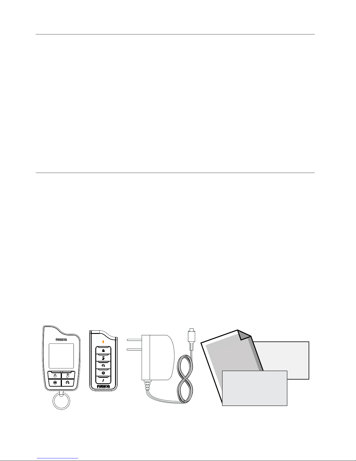
What you get
Welcome to the best generation of security with remote start. Your
system contains everything you need.
Responder HD remote control with Responder SST technology for s
superior range and reliability
1-way Companion remote controls
AC adapter for charging your remote controls
Full color owner’s guides
Quick reference cards
Warranty cards
Owner’s
Guide
Warranty
Card
Quick
Reference Card
G5902P 2009-07
Page 3

Important information
Government Regulations and Safety information
Read the Government Regulations and Warning! Safety
First sections of this manual prior to operating this system.
Warning! Failure to heed this information can result in
death, personal injury or property damage and may also
result in the illegal use of the system beyond its intended
purpose.
Your Warranty
Your Responder HD system comes with a warranty. Please make sure
you receive the warranty registration card and proof of purchase from
your dealer indicating the product was installed by an authorized
Directed dealer. Your product warranty must be validated within 10
days of purchase. You can validate it online at www.prodregister.
com/directed or complete and return the warranty registration card.
Quick Reference Card
Carry this card with you to reference your system’s many features.
Replacement remote controls
If additional remote controls are desired, please see your authorized
dealer or visit us at www.directedstore.com to order. Part numbers
are: 7941P for Responder HD 2-way remote control and 7652P
for the companion remote control. Your system can also be used with
optional Responder LC3 LCD 2-way remote control (7752P).
Page 4

Contents
Getting Started .................................................................................................... 4
Charging the remote control: ................................................................. 4
Keys to using this manual ...................................................................... 5
Remote Control Information .................................................................................. 6
Control Center ..................................................................................... 7
Status Screen Icons .............................................................................................. 8
Using your System ............................................................................................. 10
Commands and Confirmations ............................................................ 10
Navigation ....................................................................................... 10
Performing Commands ....................................................................... 10
Fault Condition Alerts ......................................................................... 11
Basic commands (function level 1) ......................................................................12
Arm ................................................................................................. 12
AUX/Trunk ........................................................................................ 12
Disarm ............................................................................................. 13
Remote Start ...................................................................................... 13
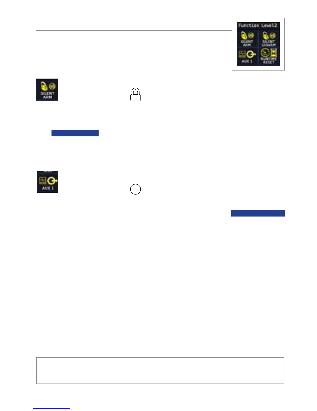
Advanced commands: Function Level 2 ............................................................... 14
Silent Arm ......................................................................................... 14
AUX 1 .............................................................................................. 14
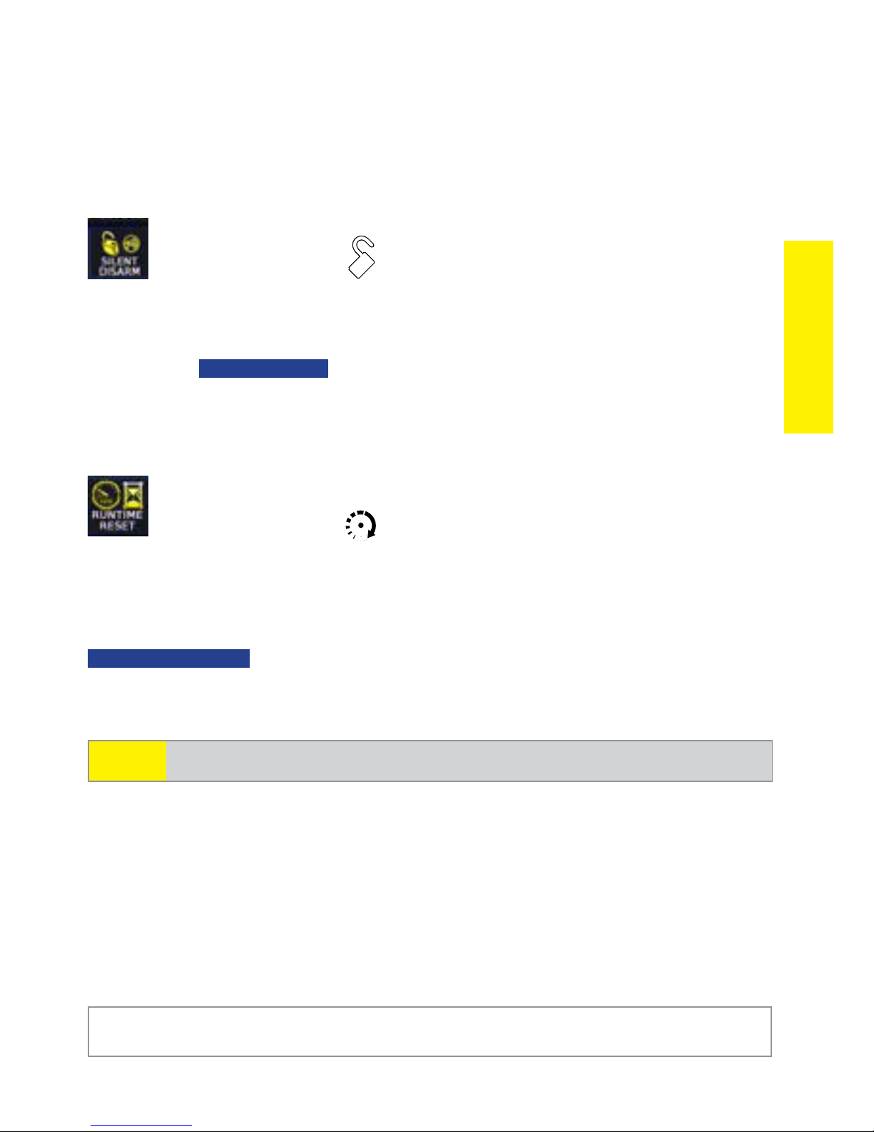
Silent Disarm ..................................................................................... 15
Runtime Reset .................................................................................... 15
Advanced commands: Function Level 3 .............................................................. 16
Sensor Bypass ................................................................................... 16
AUX 2 .............................................................................................. 16
Remote Valet .................................................................................... 17
Advanced Start ................................................................................. 17
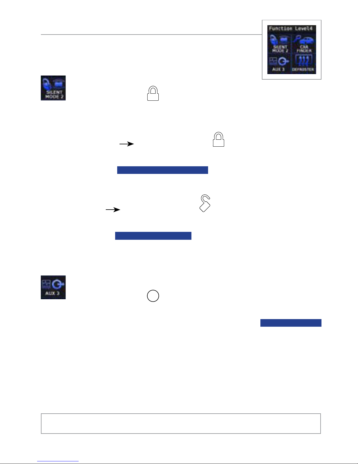
Advanced commands: Function Level 4 .............................................................. 18
Silent Mode 2 ................................................................................... 18
AUX 3 .............................................................................................. 18
Car finder ......................................................................................... 19
Defroster ........................................................................................... 19
Advanced commands: Function Level 5 ............................................................... 20
Car Select ........................................................................................ 20
AUX 4 .............................................................................................. 20
Last Trigger ....................................................................................... 21
Temp Request .................................................................................... 21
Configuring your System .................................................................................... 22
Navigating menus and configuring features ......................................... 22
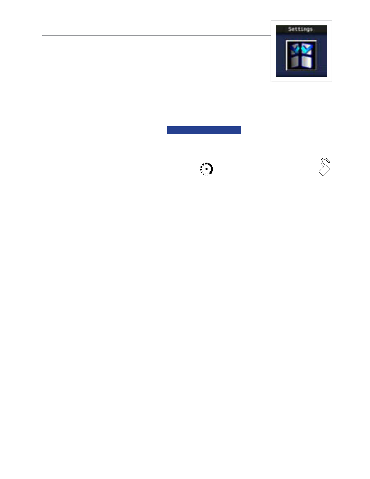
Settings Menu ................................................................................................... 24
Button Auto Lock ............................................................................... 24
Alert Types ....................................................................................... 24
Animations ....................................................................................... 24
Page 5

Button Beeps ..................................................................................... 25
Paging ............................................................................................ 25
Temp Units ....................................................................................... 25
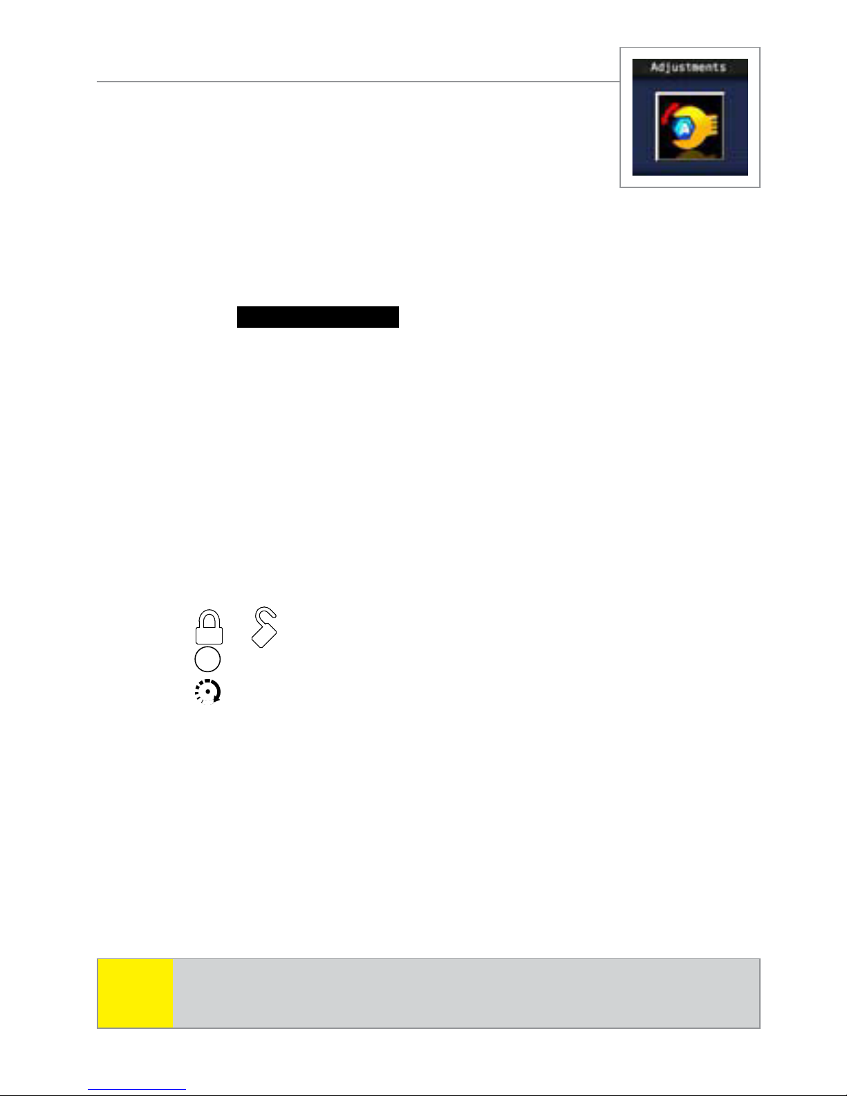
Adjustments Menu ............................................................................................. 26
Clock Settings .................................................................................. 26
Timer Start ........................................................................................ 26
Smart Start ........................................................................................ 27
Remote Pair ...................................................................................... 28
Sensor Adjust ................................................................................... 29
Options Menu ................................................................................................... 31
Power Off ........................................................................................ 31
Parking Meter .................................................................................. 31
Countdown Timer .............................................................................. 32
Name Tags ....................................................................................... 33
Demo Mode ...................................................................................... 33
Level 5 Screen ................................................................................... 34
Alarm Features .................................................................................................35
Normal Arm Protection ....................................................................... 35
Sensor Silent Arm protection ............................................................... 35
Full Silent Arm Protection .................................................................... 36
Sensor Warn-away Messages ............................................................. 36
Full trigger Messages ......................................................................... 36
Emergency Override .......................................................................... 36
Trigger Zone Fault Report.................................................................... 37
Alarm Trigger Report .......................................................................... 37
Last Trigger Report ............................................................................. 38
Nuisance Prevention (NPC) ................................................................. 38
Remote Start Features ........................................................................................ 39
Pit Stop Mode ................................................................................... 39
Key Takeover..................................................................................... 39
Remote Start Safe-lock ........................................................................ 40
Disabling Remote Start ....................................................................... 40
Advanced Start ................................................................................. 40
Temperature Reporting ........................................................................ 41
Remote Start Time-out Alert .................................................................. 42
Manual Transmission Start (MTS mode) ................................................ 42
Turbo Timer Mode .............................................................................. 43
Remote Start Not Available ................................................................. 44
Remote and System Operations .......................................................................... 45
Passive Arming .................................................................................. 45
Auto Re-arming .................................................................................. 45
Valet Mode ....................................................................................... 46
Power Save ....................................................................................... 46
Rapid Resume ................................................................................... 46
Automatic Remote Updates ................................................................. 46
Page 6

Out of Range .................................................................................... 47
No Remote Output ............................................................................. 47
Feature not Available ......................................................................... 47
No Function Assigned ........................................................................ 48
1-way Companion Remote Control ..................................................................... 49
Accessing Commands ........................................................................ 50
Sensor Bypass operation .................................................................... 50
Button Auto Lock ................................................................................ 50
Car Select ......................................................................................... 50
Programming .................................................................................... 51
Battery Information (1-Way) ................................................................ 52
System Expansion Options ................................................................................. 53
Battery Information (Responder HD) .................................................................... 55
Low Battery ....................................................................................... 55
Battery Life ........................................................................................ 56
Battery Disposal ................................................................................ 57
Glossary of Terms .............................................................................................. 58
Specifications .................................................................................................... 59
Government Regulations .................................................................................... 60
Warning! Safety First ......................................................................................... 62
Installation ........................................................................................ 62
Remote Start Capable ........................................................................ 62
Manual Transmission Vehicles ............................................................. 62
Interference ....................................................................................... 64
Upgrades and Batteries ...................................................................... 64
Water/Heat Resistance ...................................................................... 64
Limited lifetime consumer warranty ..................................................................... 65
Page 7
Getting Started
Your Responder HD remote is powered by an internal rechargeable
battery that can only be serviced by an authorized Directed dealer.
Due to transit and storage time prior to your purchase, the battery
charge may have depleted. To ensure proper operation, check the
battery level and connect the battery charger if not fully charged. See
Battery Information and Status Screen Icons sections for more information about the battery.
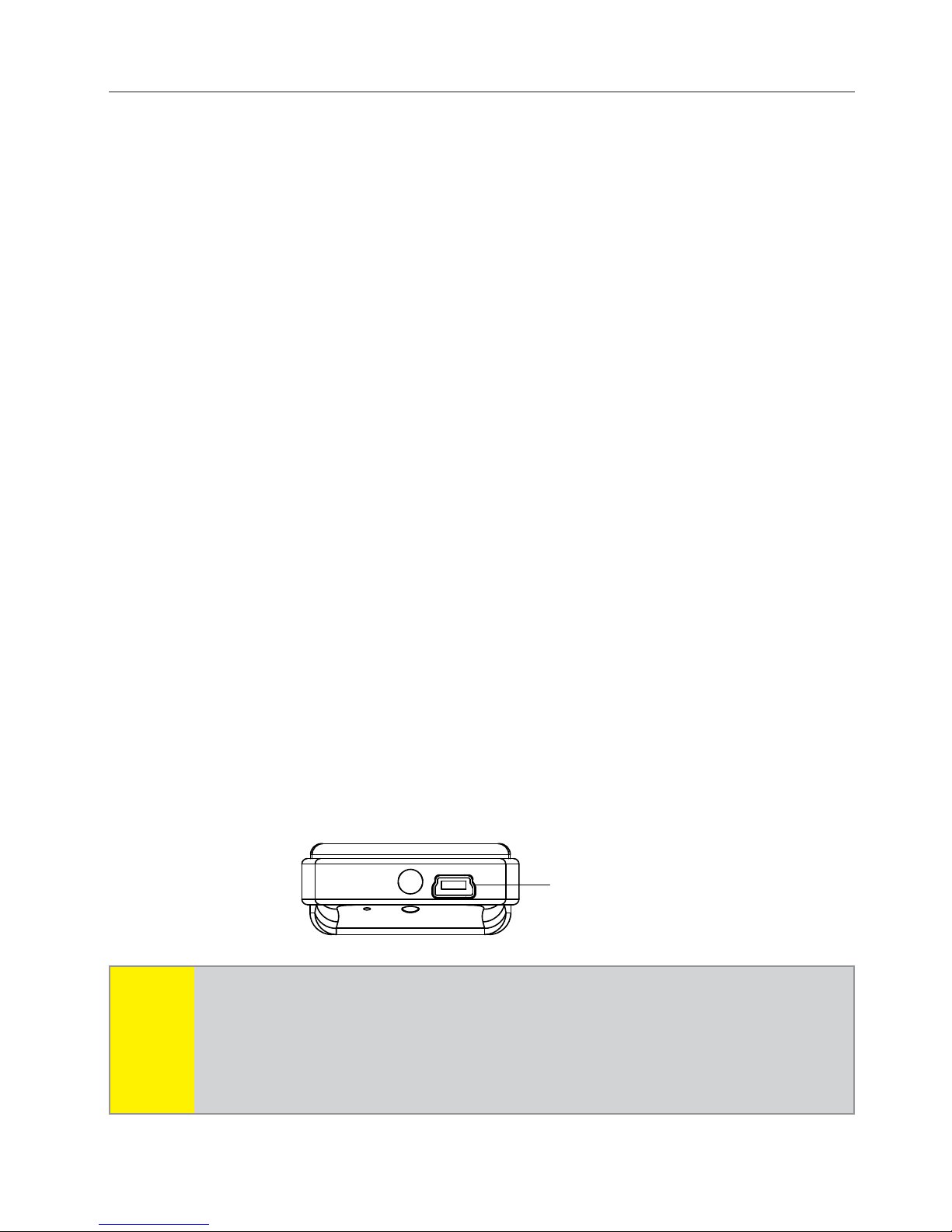
Charging the remote control:
Plug the AC adapter into a 110V AC outlet. Insert the mini-USB 1.
connector into the port on the remote control. The Status screen
Note
Info Center then indicates the remote control is charging.
While the Status screen is off, the blue transmit LED will continue 2.
blinking until fully charged (the remote control also remains
functional to command the system or access the Status screen to
check the battery level).
Once fully charged the remote control is ready for use. Discon-3.
nect the mini-USB end from the remote control first and then the
AC adapter from the AC outlet.
Mini-USB
Port
If the battery is excessively depleted when the charger is
connected, functionality may be delayed while it charges to
the minimum voltage required to operate the display, after
which normal charging resumes.
4
© 2009 Directed Electronics. All rights reserved.
Page 8

Keys to using this manual
Specific actions (in bold type) and style conventions are used consistently throughout this manual, they are as follows:
Toggle: s implies rolling the menu wheel up or down and releas-
ing.
Press: s implies pushing directly inward on the menu wheel or com-
mand button and releasing.
Hold: s is used after Toggle or Press actions when the menu wheel
or command button needs to be held in position for an extended
period of time, typically several seconds.
At a Glance
s this style denotes a still or an animation shown on the
ARMED
HD display, labeled specifically with the command it identifies.
s denotes highlighted on-screen text when configuring
Set Clock
the system or remote control.
Blues text denotes non-highlighted screen titles or on-screen text
(such as used in the configuration menus).
Italicizeds words denote section/sub headings in this guide and
can be located through the table of contents.
An asterisk (*) when used after a word or phrase denotes that s
additional details can be found in related sections usually noted
at the bottom of the page or end of the section.
© 2009 Directed Electronics. All rights reserved.
5
Page 9
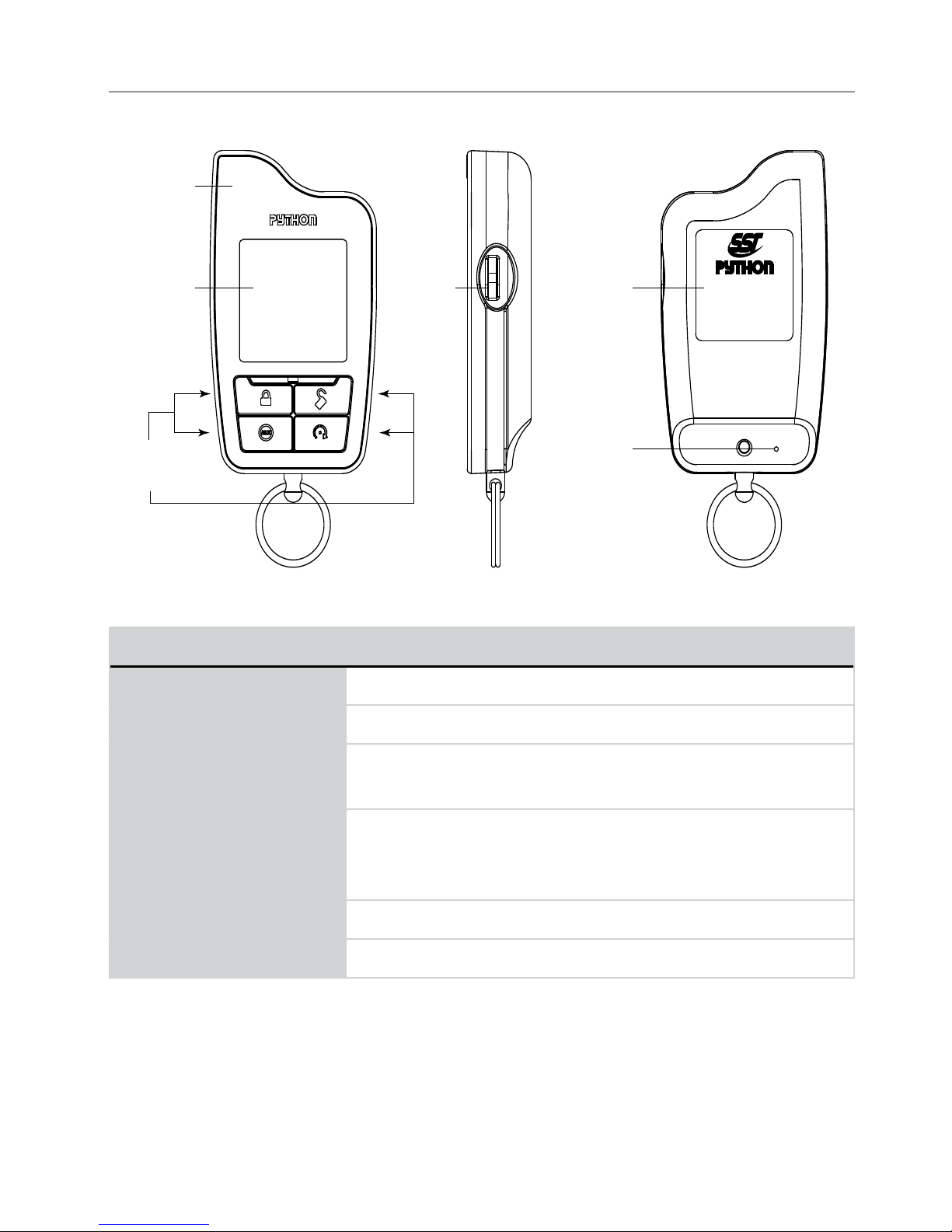
Remote Control Information
Internal
Antenna
Display
Command
Buttons
Menu
Wheel
Remote
Details
Reset
Button
1-800-274-0200
RPN 7941P
IC: 1513A-7941
FCC ID:EZSDEI7941
Feature Description
Internal Antenna* Used for transmitting and receiving information
Display Full color display
Command buttons (4): Used to perform arming, disarming, auxiliary channel and
remote start commands
Menu wheel Used to access Function Level screens, control Status
Screen info center content, and navigates the remote
control and system configuration menus
Reset Button** Resets the remote control’s microprocessor
Mini USB Port Used for charging the internal battery (not shown)
* Avoid touching or grasping the area where the internal antenna is located as it may
reduce range.
** Should the remote stop responding to button presses, insert a pin or the end of a
paper clip, and press in on the reset button for one second.
6
© 2009 Directed Electronics. All rights reserved.
Page 10

Control Center
At a Glance
Status LED
Control button
The Control Center, typically located on the upper part of the front
windshield sends and receives commands or messages to and from
your system. It consists of:
The In-vehicle system antenna, for 2 way communication. s
The Status LED, as a visual indicator of the system’s status. s
The Control button, for placing the system into Valet Mode* and s
to perform the Emergency Override** operation.
* See Remote and System Operations section for details.
** See
© 2009 Directed Electronics. All rights reserved.
Alarm Features for details.
7
Page 11

Status Screen Icons
Clock
Page/Alerts
Siren Status
Sensor Status
Info Center
Name Tag
Battery Level
Timer Mode/Smart Start
Remote Start Status
System Status
The table below describes all the Status screen icons.
Feature Description
Clock Indicates the time in 12 or 24 hour format
Battery level
Full ¾ ½ ¼ Empty
Timer Mode
/ Smart Start
Remote Start
System Status
Timer Mode is enabled. Smart Start is enabled.
Remote start is active, the engine is running. Manual
Transmission Start mode is enabled, the engine can be started
The system is armed, the alarm is enabled.
The system is disarmed, the alarm is disabled.
The system is Locked in Valet, the alarm is disabled.
The system is Unlocked in Valet, the alarm is disabled.
Second system operation: If set to control a second system, the
above lock icons will contain a “2”.
8
© 2009 Directed Electronics. All rights reserved.
Page 12
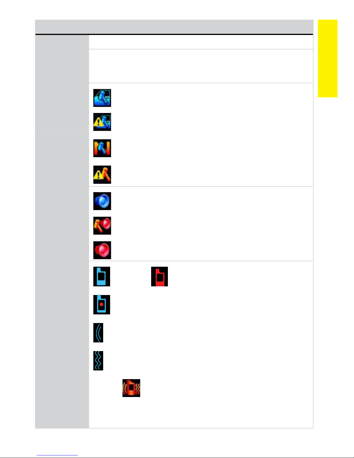
Feature Description
Name Tag Displays a personalized name tag 1-15 characters long
Info Center Displays the Remote Start runtime, Temperature Auto-report, Parking
meter and Countdown timers. While Status screen is on, press the
menu wheel to change the displayed information.
At a Glance
Sensor Status
Siren Status
Trigger Zones are enabled and functioning normally.
Trigger zone fault found when arming and is bypassed.
NPC On, a sensor has triggered excessively and is bypassed
Remote Sensor bypass On, the bypassed sensor will not
trigger the alarm.
Siren is enabled and will sound for all alarm outputs.
Siren is disabled for sensor triggers, remote is paged for all
triggers (Sensor Silent Arm).
Siren is disabled for all triggers, remote is paged for all trig-
gers (Full Silent Arm).
Page/Alerts
Pager On, Pager Off.
Battery Save On (Red dot), Battery Save Off (No dot).
Tone On (icon is not present when Tone is Off).
Vibrate On (icon is not present when Vibrate is Off).
Example
Page Off, Vibrate On & Tone On.
Varying combinations of these icons reflect the Paging and Alert
Types menu settings.
© 2009 Directed Electronics. All rights reserved.
9
Page 13

Using your System
Commands and Confirmations
Commands, Basic or Advanced, are used to activate system features
and are performed by pressing one of the Command buttons. Basic
commands control the most often used security and remote start features while Advanced commands control more specialized features
and request reports.
Confirmations for Basic or Advanced commands are indicated
first by siren chirps and vehicle light flashes, and then as animations,
still screens and beeps or tones on the remote control. A description
of each feature confirmation is found in the following Basic command
and Advanced command sections.
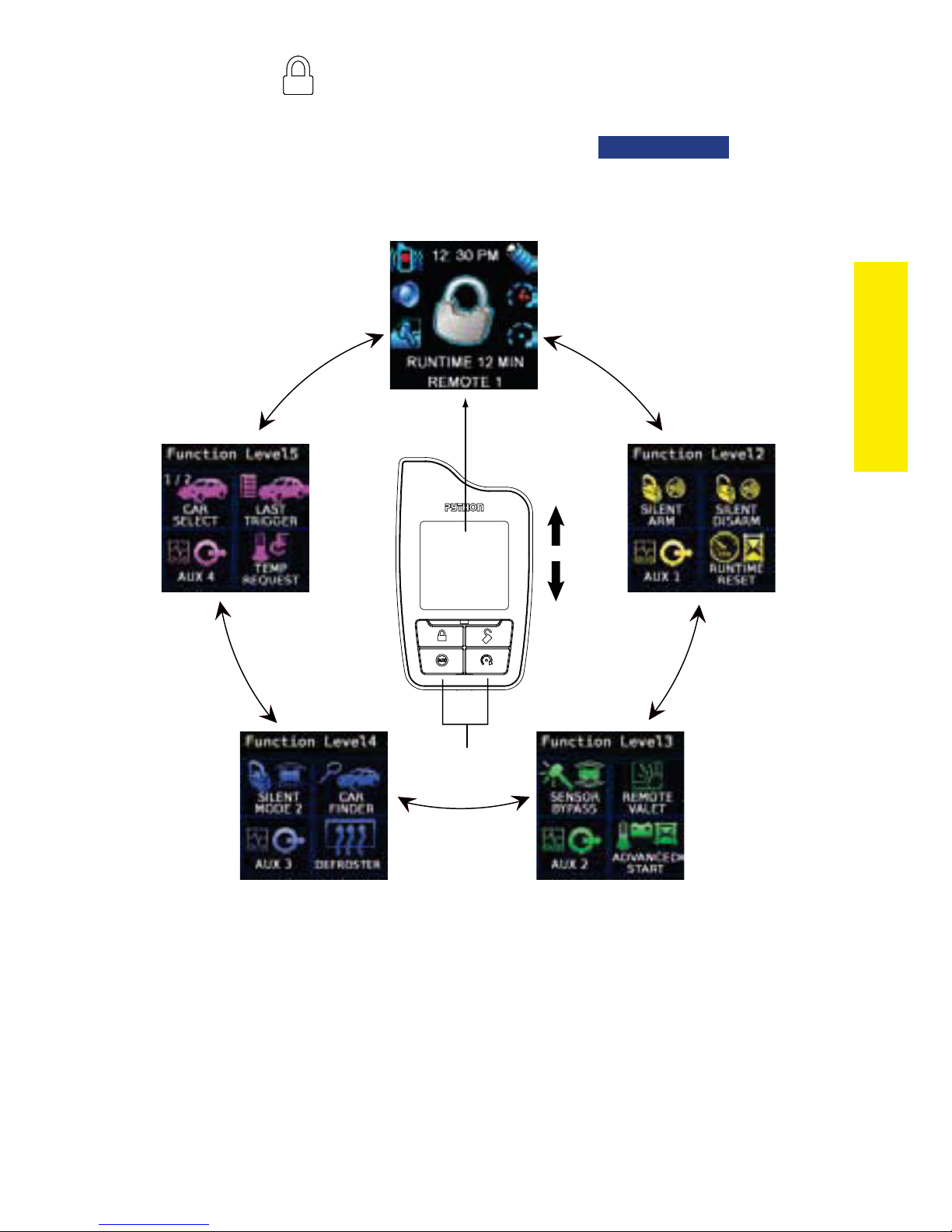
Navigation
To navigate to the Status and Function level screens, toggle the menu
wheel up or down, the screens will cycle as shown in the facing diagram. These screens remain displayed for 3 seconds before reverting
to a blank screen. To display a screen for an extended 20 second
period; toggle and hold the menu wheel on the desired screen for this
duration, after which the display reverts to a blank screen.
Performing Commands
Perform Basic commands by pressing one of the command buttons
while the remote control display is blank or the Status screen is On.
Perform Advanced commands by pressing one of the command buttons while a Function Level screen is displayed.
Advanced command example: Silent Arm
Toggle1. the menu wheel to display the
10
Function Level 2 screen.
© 2009 Directed Electronics. All rights reserved.
Page 14
Press2. the button while this screen is still on to perform the
Silent Arm command.
The Responder HD remote will play the 3.
followed by the Status screen.
Status Screen
Blank
Display
SILENT ARM
Toggle
Menu Wheel
Up or Down
animation
Commands
Command
Buttons
Fault Condition Alerts
If, when performing a command, a condition exists that does not allow the activation of a feature, a fault screen and tone plays as an
alert. For more details on the condition and possible resolutions, use
the fault screen title and locate the respective section through the table
of contents.
© 2009 Directed Electronics. All rights reserved.
11
Page 15
Basic commands (function level 1)
Arm
Press and release
The alarm arms, doors lock (if connected), and the siren chirps and
lights flash once. The
Valet mode* is On the doors lock and the
ARMED
animation and beeps play to confirm. If
LOCKED (IN VALET)
anima-
tion and tone play. Exit Valet mode to arm the alarm normally.
If a trigger zone fault is detected the siren chirps once again and the
Trigger Zone Fault report** plays.
To Arm and Panic
Press and hold
The alarm Arms (or Locks in Valet) and, after 2 seconds, sounds
the siren and flashes the lights. The
tones play to confirm. Press the
PANIC
animation and siren
or button to stop the out-
put.
AUX/Trunk
Press and hold
The Trunk opens (if connected) when this button is pressed for 2 seconds. The
* See Remote and System Operations section for details.
** See
12
AUX
TRUNK RELEASE
animation and tones play to confirm.
Alarm Features for details.
© 2009 Directed Electronics. All rights reserved.
Page 16
Disarm
Press and release
The alarm disarms, doors unlock (if connected), and the siren chirps
and lights flash twice. The
firm. If Valet mode* is On the doors unlock and the
DISARM
animation and beeps play to con-
UNLOCK (IN VALET)
animation and tone play.
More than 2 siren chirps and remote beeps indicates a trigger has
occurred. The Disarm animation is then replaced by the Alarm Trigger
report.**
Remote Start
Press and release
Activates (or if On, deactivates) the remote starter. The engine and lights
turn On and the
or the engine and lights turn Off and the
REMOTE START ACTIVATED
animation and On tones play,
REMOTE START DEACTIVATED
Commands
animation and Off tones play to confirm. The Remote Start status icons
in the Status screen are updated accordingly. If Remote Start fails to
activate, a fault screen and tone plays to identify the reason.***
* See Remote and System Operations for details.
** See
*** See
For Manual transmission vehicles see the
tion under
© 2009 Directed Electronics. All rights reserved.
Alarm Features for details.
Remote Start Not Available (Remote Start Features).
Remote Start Features for more details.
Manual Transmission Start sec-
13
Page 17
Advanced commands: Function Level 2
From blank screen, toggle menu wheel down 2 times
Silent Arm
Press and release
The alarm arms, doors lock (if connected), and the lights flash once.
The
SILENT ARM
animation plays to confirm. Valet mode* or Trigger
Zone Fault report** messages may be received.
AUX 1
Press and release
Activates (or if On, deactivates) the Aux 1 output. The
animation and On tones or Off tones play to confirm.
AUX
AUX CHANNEL
* See Remote and System Operations section for details.
** See
14
Alarm Features for details.
© 2009 Directed Electronics. All rights reserved.
Page 18
Silent Disarm
Press and release
The alarm disarms, doors unlock (if connected), and the lights flash
twice. The
SILENT DISARM
animation plays to confirm. The Alarm Trig-
ger report* may replace the Silent Disarm animation.
Runtime Reset
Press and release
If more time is needed while remote start is active, runtime reset
will reset the runtime counter to the pre-programmed setting. The
RUNTIME RESET
animation and tones play to confirm. The Remote
Commands
Start runtime is reset in the Status screen.
Note
* See Alarm Features for details.
© 2009 Directed Electronics. All rights reserved.
Remote Start must be active to use this feature.
15
Page 19
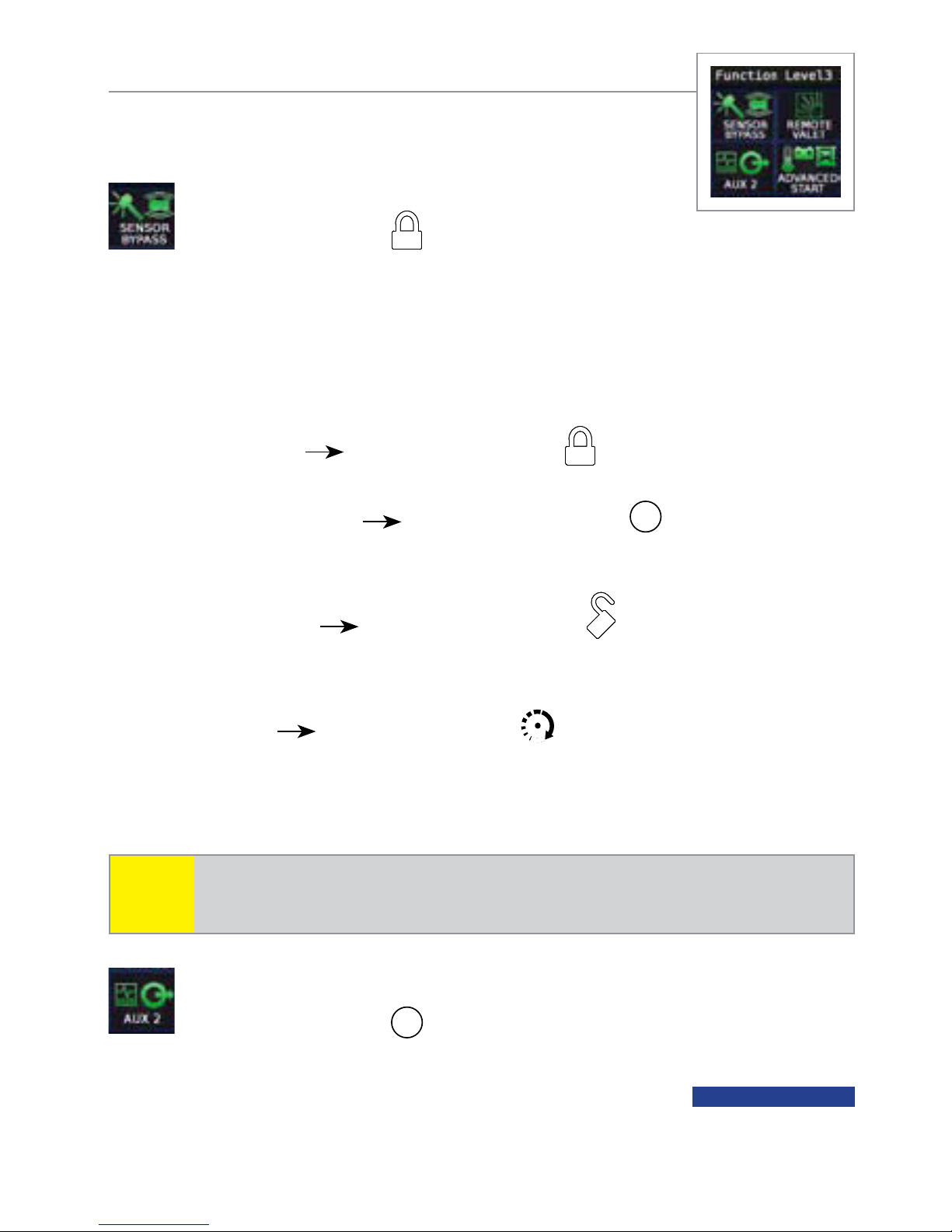
Advanced commands: Function Level 3
From blank screen, toggle menu wheel down 3 times
Sensor Bypass
Press and release to access menu
The Sensor Bypass menu screen has four options, pressing the appropriate button as shown below activates that bypass level. An appropriate screen and beeps play to confirm.
Warn away
Press and release : all sensor warn-away
output and messages to the remote are defeated.
Optional sensors
Press and release
AUX
: optional sensor
warn-away and full trigger output and messages to the remote
are defeated.
Shock sensor
Press and release : shock sensor warn-
away and full trigger output and messages to the remote are
defeated.
Bypass all
Press and release : shock and optional sensor
warn-away and full trigger output and messages to the remote
are defeated.
Note
System needs to be armed to perform Sensor Bypass.
Perform arm command any time to turn Sensor Bypass Off.
AUX 2
Press and release
Activates (or if On, deactivates) the Aux 2 output. The
animation and On tones or Off tones play to confirm.
16
AUX
AUX CHANNEL
© 2009 Directed Electronics. All rights reserved.
Page 20
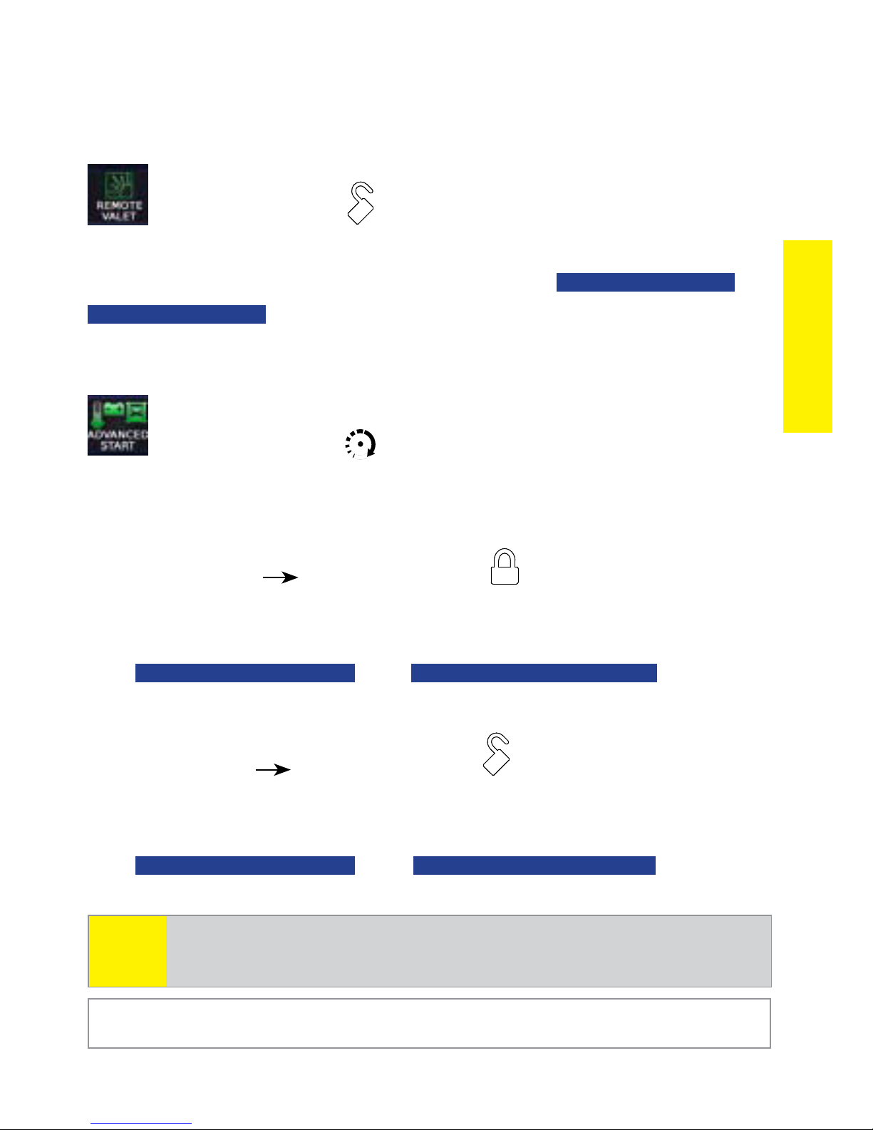
Remote Valet
Press and release
Enters (or if On, exits) Valet Mode. The
EXIT VALET MODE
animation and beeps play to confirm. See Valet
VALET MODE ENTER
Mode for more details
Advanced Start*
Press and release
Displays the Advanced Start menu screen with two options:
Timer Mode
Activates (or if On, deactivates) Timer Mode. The lights flash
quickly four times for On and slowly four times for Off. The
TIMER MODE ACTIVATED
Press and release :
or
TIMER MODE DEACTIVATED
animation
or
Commands
and beeps play to confirm.
Smart Start Press and release :
Activates (or if On, deactivates) Smart Start. The lights flash
quickly five times for On and slowly five times for Off. The
SMART START ACTIVATED
and beeps play to confirm.
Note
Advanced Start will not start the engine unless the system
has been Armed or Locked In Valet.
* See Remote Start Features for more details.
© 2009 Directed Electronics. All rights reserved.
or
SMART START DEACTIVATED
animation
17
Page 21
Advanced commands: Function Level 4
From blank screen, toggle menu wheel down 4 times
Silent Mode 2
Press and release
Displays Silent mode 2 menu screen with two options:
Sensor Silent*
Press and release
The alarm arms, doors lock, and the siren chirps and lights flash
3 times. The
SENSOR SILENT MODE
screen and beeps play to
confirm.
Full Silent* Press and release :
The alarm arms, doors lock, and the siren chirps and lights flash
4 times. The
FULL SILENT MODE
screen and beeps play to con-
firm.
AUX 3
Press and release
AUX
Activates (or if On, deactivates) the Aux 3 output. The
animation and On tones or Off tones play to confirm.
* See Alarm Features for more details.
18
AUX CHANNEL
© 2009 Directed Electronics. All rights reserved.
Page 22
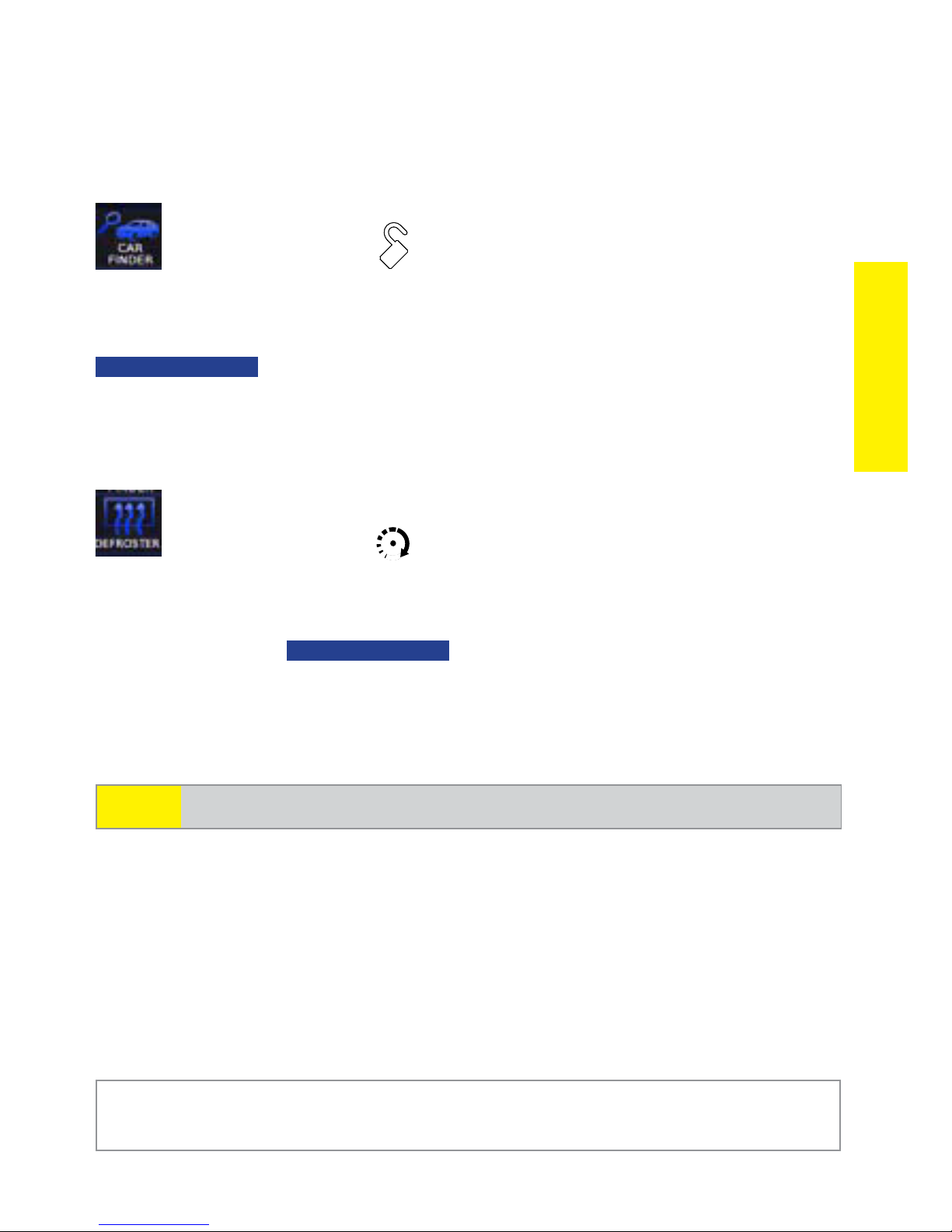
Car finder
Press and release
The siren emits one long chirp and the lights flash for 10 seconds. The
Commands
CAR FINDER
animation and beeps play to confirm. The light flashes
stop if armed or disarmed while Car Finder is in progress.
Defroster*
Press and release
Activates the vehicle Defroster circuit (if connected) while Remote Start
is activated. The
For convenience, the Defroster circuit will also automatically activate
10 seconds after remote starting if the temperature is below 55°F.
Note
Remote Start must be active to use this feature.
DEFROSTER ON
screen and beeps play to confirm.
* This feature must be installed and turned on by an authorized Directed
dealer.
© 2009 Directed Electronics. All rights reserved.
19
Page 23
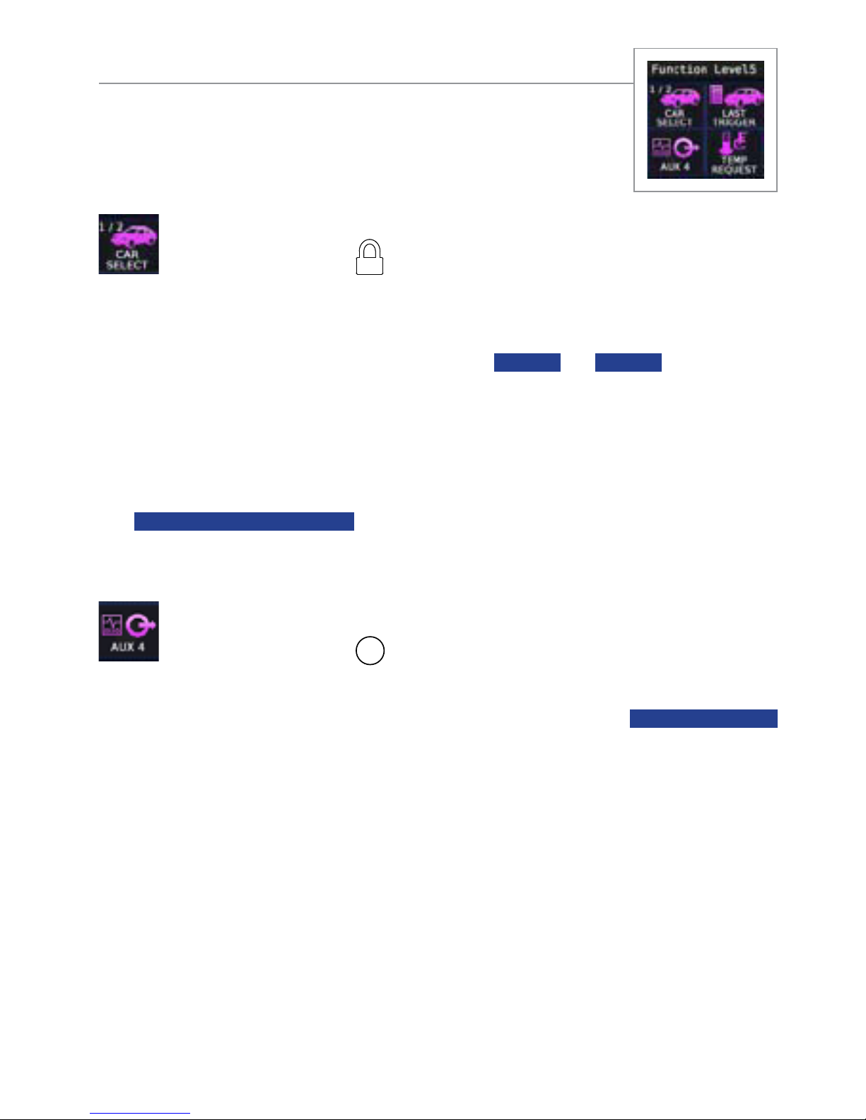
Advanced commands: Function Level 5
From blank screen, toggle menu wheel down 5 times
Car Select
Press and release
Sends a request message to the selected car which, if within range,
responds with its status information. The
CAR 1
or
CAR 2
screen and
beeps play to confirm the change followed by the updated Status
screen.
Car 2 must have a Name Tag set in the Options menu before it can
be selected. If the selected car does not respond the remote displays
the
CAR 1 NOT AVAILABLE
screen (or car 2 if applicable) and remains
in the newly selected car mode.
AUX 4
Press and release
Activates (or if On, deactivates) the Aux 4 output. The
screen and On tones or Off tones play to confirm.
AUX
AUX CHANNEL
20
© 2009 Directed Electronics. All rights reserved.
Page 24
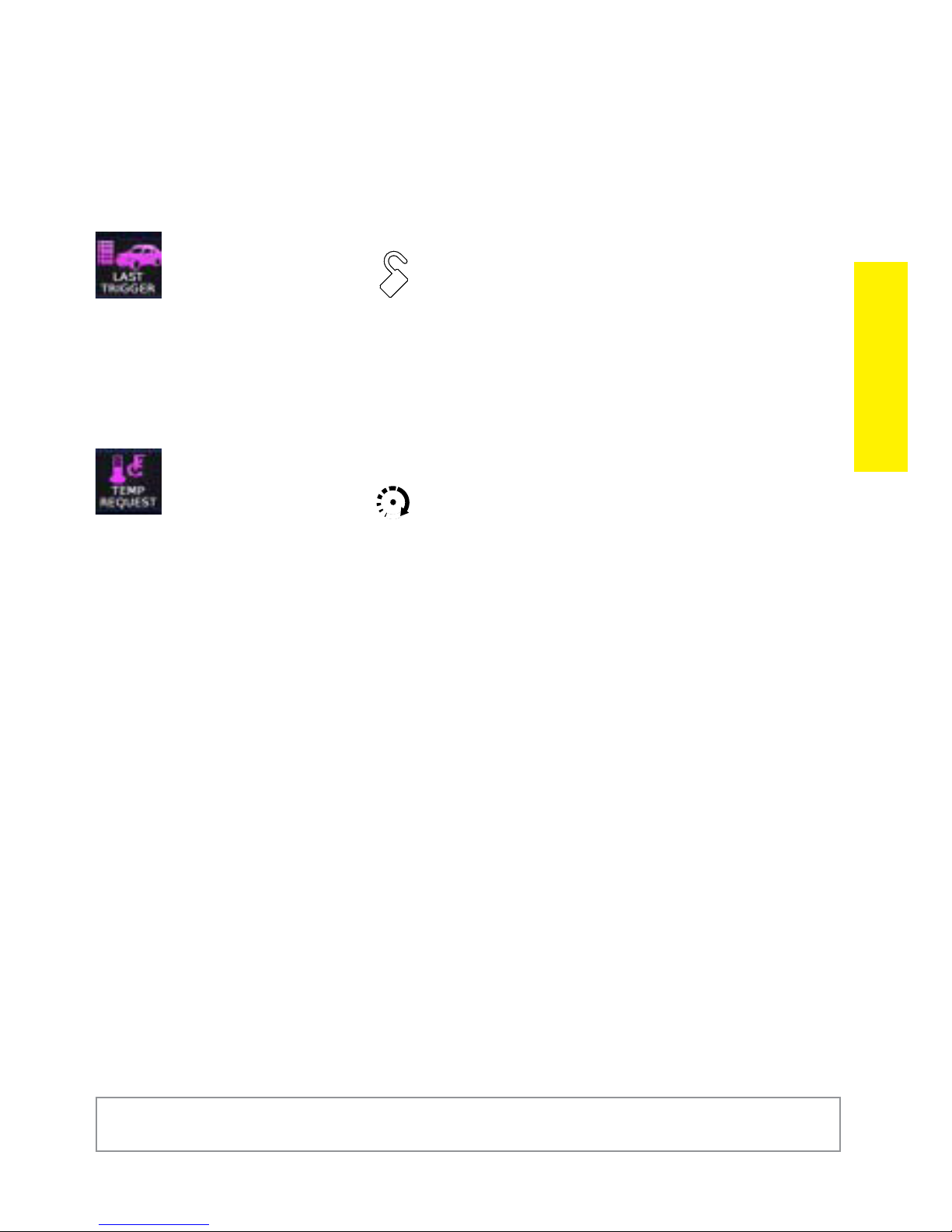
Last Trigger*
Press and release
Requests a report of the most recent alarm triggers for display on the
remote. The last trigger report clears when the ignition is turned on.
Temp Request
Press and release
Requests the vehicle’s interior temperature and temporarily displays it
in the status screen info center.
Commands
* See Alarm Features for more details.
© 2009 Directed Electronics. All rights reserved.
21
Page 25
Configuring your System
You can customize the way the HD remote communicates information
and adjust a variety of system features in the
Settings, Adjustments and
Options configuration menus. The following features are listed and
defined in the same sequential order as they appear on your system.
Button Auto Lock
Alert Types
Animations
Button Beeps
Paging
Temp Units
Clock Settings
Timer Start
Smart Start
Remote Pair
Sensor Adjust
Power Off
Parking Meter
Countdown Timer
Name Tags
Demo Mode
Level 5 screen
No features, used
only to exit menus
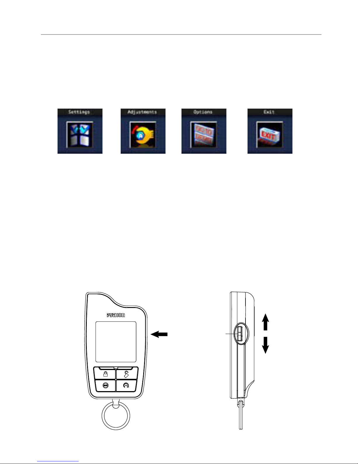
Navigating menus and configuring features
Configuring your system is performed via the menu wheel and command buttons.
Menu
Wheel
Press in
to Enter
Toggle Up
Toggle Down
22
© 2009 Directed Electronics. All rights reserved.
Page 26

The following instructions discuss how to access and configure the
many features available, allowing you to customize your HD remote
control to your personal preferences.
To access the main menu screens (from a blank display):
Press1. and hold the menu wheel for 3 seconds, the remote control
enters the main menu and displays the
Toggle2. the menu wheel to scroll through the
Adjustments and Exit main menu screens.
Press3. the menu wheel to enter a displayed main menu.
Toggle4. the menu wheel to highlight a menu item.
Press5. the menu wheel to access the menu item screen.
Making selections, go back and exit:
Toggle6. the menu wheel to move the highlight to the desired con-
figuration and then press to set. The selected configuration is
indicated by the pointer on the right. Continue to hold the menu
wheel to return to normal operation or release to remain within
the menu. Highlight
Back
and press to return to the previous
Settings screen.
Settings, Options,
Configurations
menu or continue holding to return to normal operation.
Adjust timers and features
When adjustment screens are accessed, the current settings are 7.
displayed. Toggle the menu wheel to highlight a settings field
and then press it to adjust the setting. Follow the on-screen instructions or the description in each feature section to adjust the
feature settings.
Menus are automatically exited after a 30 second lapse in button
activity.
© 2009 Directed Electronics. All rights reserved.
23
Page 27
Settings Menu
Button Auto Lock
Options: ON, OFF (default)
When
tween button presses to prevent unintentional operations. If a button
is pressed when locked the
When OFF, the buttons do not lock and always perform a command
when pressed.
button, the Status screen and unlock tones play to confirm.
Auto unlocking: After turning the ignition off, a message to the remote
unlocks the buttons until the next command is performed. If Auto Unlocking is not desired, it can be turned off by an authorized Directed
Dealer.
ON, the remote buttons lock after a 20 second lapse be-
BUTTON LOCK ON
To unlock the buttons; press the
button followed by the
and fault tone play.
Alert Types
Options: Tone (default), Tone+Vibrate, Vibrate, Screen Only
There are several ways for the HD to alert you when it has received a
message from the system. Select Tone to be alerted by tones that are
unique for each message. Select Vibrate and the HD silently alerts you
with a gentle vibration. Select Tone+Vibrate to be alerted by both, or
select
Screen Only when you don’t want to be interrupted.
Animations
Options: Play All (default), Triggers Only
24
© 2009 Directed Electronics. All rights reserved.
Page 28

Select Play All and all available animations and still screens play
when a message is received from the system. Select
Triggers Only and
the animations are only played if a message indicating the security
system has triggered and the siren is sounding. Screen stills are active
for features in this selection.
Button Beeps
Options: ON (default), OFF
When Button Beeps are ON you hear a beep each time you press
a button. These beeps can be turned OFF if you prefer silent button
presses.
Paging
Configurations
Options: Battery Save (default), ON, OFF
Paging is how the HD remote monitors your system’s messages. Battery Save extends battery life by turning Paging Off after 72 hours if
the remote control is not used during this period. Just press any button
to resume system monitoring. When
onds to listen for pages from the system. When
ON it wakes up every few sec-
OFF it does not wake
up to receive remote start or alarm trigger pages.
Note
When off, responses are still received when a command
is performed.
Temp Units
Options: Fahrenheit (default), Celsius
Temperature can be displayed in your choice of temperature scales.
© 2009 Directed Electronics. All rights reserved.
25
Page 29
Adjustments Menu
Clock Settings
Options: Set Clock, Time Format
Used to adjust the clock and set the Status screen time format.
Setting the clock
Toggle1. to
Clock Settings
and press the menu wheel, the Clock
Settings screen is displayed.
Press2. the menu wheel to enter the
Set Clock field, or toggle to
Time Format to select a 12 Hour or 24 Hour display and press
the menu wheel on your highlighted choice to set (a pointer to the
right indicates your selection).
In the3.
Set Clock field, to adjust and save a new clock setting,
follow the on-screen instructions.
Menu wheel: s Press the menu wheel to highlight the charac-
ter to be adjusted. Toggle to adjust up/down.
s or : Press to highlight the character to be adjusted.
s : Press to reset the clock.
AUX
s : Press to save new settings and go back to the Clock
Settings screen.
Timer Start*
Options: How Many? (Starts), How Often? (Hours)
The Timer Start adjustment screens are used to set how many times (1
- 24 starts) and how often (every 1-24 hours) the Timer Mode feature
starts the engine, when enabled.
Note
26
Before beginning adjustment the system must be in communication range of the remote and in the disarmed state.
© 2009 Directed Electronics. All rights reserved.
Page 30
Setting Timer Start
Disarm1. the system then access the Adjustments feature menu.
Toggle 2. to
Start
screen with current setting is displayed. If the system is not
ready the
Timer Start
NO FUNCTION ASSIGNED
and press the menu wheel, the Timer
screen and tone plays. Return
to Step 1.
Press3. the menu wheel to enter the
toggle and press to enter the
How Often? (Hours) field.
How Many? (Starts)
field or
To adjust and save new settings follow the on-screen instruction.4.
Menu Wheel: s toggle to adjust the setting up/down.
s or : Press to adjust the setting up/down.
s : Press to reset the setting to default.
AUX
s : Press to delete new settings and go back to the Adjust-
ment feature menu.
Configurations
* See Advanced Start under Remote Start Features for more details.
Smart Start*
Options: Low Temp Start, High Temp Start
The Smart Start adjustment screens are used to set the low temperature
and high temperature thresholds the Smart Start feature uses to start the
engine, when enabled.
Note
Setting the Low and High Temperature thresholds:
Before beginning adjustment the system must be in communication range of the remote and in the disarmed state.
Disarm1. the system then access the Adjustments feature menu.
Toggle 2. to
Smart Start
Start screen with current setting is displayed. If the system is not
© 2009 Directed Electronics. All rights reserved.
and press the menu wheel, the Smart
27
Page 31

ready the
to Step 1.
NO FUNCTION ASSIGNED
screen and tone plays, return
Press3. the menu wheel to enter the
toggle and press to enter the
High Temp Start field.
Low Temp Start
To adjust and save new settings follow the on-screen instruc-4.
tions.
Menu Wheel:s Toggle to adjust the setting up/down. Press
to save new settings and go back to the Adjustments feature
menu.
s or : Press to adjust the setting up/down.
s : Press to reset the setting to default.
AUX
s : Press to delete new settings and go back to the Adjust-
ment feature menu.
* See Remote Start Features for more details.
field or
Adjusting Battery Level:
The battery level threshold for the Smart Start feature is preset to
On-10.5 volts; your authorized Directed dealer can adjust this setting
within the 9 to 12 volt range or to Off.
Remote Pair
Remote Pair is a process where the Responder HD and the system in
the vehicle learn each others encrypted identification, securing their
communication from intruders. Please note that your remote controls
come pre-programmed from the factory.
How to Remote Pair
Make sure the remote control is set for the desired Car 1 or Car 2
operation for the system it is to be paired with.
28
© 2009 Directed Electronics. All rights reserved.
Page 32

Placing the system into the remote pair mode
Open1. one or more of the vehicle doors.
Turn2. the ignition to the On position.
Press3. , release, then press and hold the Control button (on Con-
trol Center).
The control center LED begins to flash and the siren emits one 4.
chirp to confirm the system is in Pair mode, the Control button
can be released. The system will stay in Pair mode for 60
seconds or until the doors are closed or ignition turned off.
The siren will emit one short and one long chirp when it exits
remote pair mode.
Toggle 1. to
screen with on-screen instructions is displayed.
Pair
Remote Pair
Press2. and hold the
and press the menu wheel, the Remote
button. The remote’s LED flashes, then
the siren chirps, and remote tones play to confirm pairing. The
PAIRING SUCCESSFUL
screen is displayed before returning to the
Adjustments feature menu screen.
If the remote does not learn the system ID it displays the 3.
PAIRING FAILED
screen after the button is released before re-
turning to the Remote Pair screen. Press and hold the
button to try again. If the siren chirps but remote tones are not
played, Press and hold the
button to try again until the
tones are played. If the siren does not chirp shortly after the
remote LED begins flashing make sure the system is in remote
Configurations
pair mode.
Sensor Adjust
Your Responder HD security with remote start system has a built in
shock sensor used to detect intrusion attempts on your vehicle. The
sensor sensitivity can be adjusted to optimize your vehicle’s detection
© 2009 Directed Electronics. All rights reserved.
29
Page 33

levels without generating false alarms.
If you feel your security system shock sensor is too sensitive or not
sensitive enough, it is highly recommended that you contact your authorized Directed dealer/professional and have the sensor adjusted
for optimized security detection performance.
30
© 2009 Directed Electronics. All rights reserved.
Page 34

Options Menu
Power Off
Options: Power Off
With
POWER OFF
Power Off
animation and tones play to confirm. When an ex-
highlighted, press the menu wheel, the
tended period of non-use is anticipated turning the power off will
preserve the battery charge.
To turn the remote on, Press and hold the menu wheel for 3 sec-
onds, the
PYTHON
animation and On tones play to confirm the remote
control is ready for normal operation. The remote also turns itself on
and begins charging when the battery charger is connected.
Parking Meter
Options: Start Meter, Parking Meter Set
The Parking Meter tracks and alerts you to the time remaining when
Configurations
parked in a metered parking spot. As the metered time runs out the remote control emits alerts at 15 minutes remaining (1 beep) and 5 minutes
remaining (2 beeps). At expiration the
PARKING METER TIMER EXPIRED
animation and 4 beeps are played followed by an alert output of 2
beeps each minute for 10 minutes. The next button press replays the
animation and stops the alert output, a command is not performed.
Starting and Setting the Parking Meter
Toggle1. to
Parking Meter
and press the menu wheel, the Parking
Meter screen with current setting is displayed.
With 2.
Start Meter
highlighted, press the menu wheel to start
the meter or toggle the Menu Wheel to enter the Parking Meter
Set field.
© 2009 Directed Electronics. All rights reserved.
31
Page 35

To adjust and save a new meter setting follow the on-screen in-3.
structions.
Menu wheel: s Press to highlight the digit to be adjusted.
Toggle to adjust the setting up/down.
s or : Press to highlight the digit to be adjusted.
s : Press to reset the meter.
AUX
s : Press to save new setting and go back to the Parking
Meter screen.
To Stop, Start and Clear the Parking Meter time (in the Info Center):
With the Status screen displayed,s press and hold the menu
wheel for 3 seconds, the colon in the timer meter stops
blinking and 2 beeps are emitted to confirm the meter has
stopped. The meter remains in the display.
Presss and hold again for 3 seconds to restart the meter (the
timer meter colon begins blinking again).
Presss and hold for 6 seconds any time, the timer will clear
from the display.
Countdown Timer
Options: Start Timer, Countdown Timer Set
Your Responder HD remote control has a feature for setting a countdown timer designed to be used as a reminder only. At expiration the
COUNTDOWN TIMER EXPIRED
an alert output of 2 beeps every minute for 10 minutes.
Setting, Stopping, Starting and Clearing of the Countdown timer and
alert uses the same process as previously described for the
Meter.
32
animation and 4 beeps play followed by
Parking
© 2009 Directed Electronics. All rights reserved.
Page 36

Name Tags
Options: Set Name Tag1, Set Name Tag2
Name tags allow you to personalize your Responder HD remote control by adding a unique name to the Status screen for the system it
controls. For Name Tag1;
Remote 1 is the default setting. Name Tag2
is used when your Responder HD remote control is used to control
a companion system in another vehicle. For more details on Name
Tag2, please contact your authorized Directed dealer.
Setting the Name Tags
Toggle1. to
Name Tags
and press the Name Tags screen is dis-
played.
Toggle2. to
Set Name Tag1
or
Set Name Tag2
and press the
menu wheel to enter the field.
To set and save a name tag follow the on-screen instructions.3.
Menu wheel: s Toggle the menu wheel up/down to adjust the
highlighted character. Press to move the highlight to the next
Configurations
character on the right.
s or : Press to highlight the character to be changed.
s : Press to delete all characters.
AUX
s : Press to save the name tag and go back to the Name
Tags
screen.
Demo Mode
Options: Demo Once, Demo Once muted, Demo loop, Demo loop
muted
Demo Mode
stration tool to show friends or family. Running it shortens the battery
life over time if used excessively. Please note that the accelerated
plays a pre-selected group of animations as a demon-
© 2009 Directed Electronics. All rights reserved.
33
Page 37

battery depletion caused by this using this feature can result in a dead
battery. Use sparingly to maintain battery life.
Demo Once plays the animations once with tones and beeps;
Demo Once Muted plays animations only.
Demo Loop plays the animations continuously with tones and
beeps;
Note
Demo Loop Muted plays animations only.
The supplied battery charger must be connected to your
Responder HD remote control for Demo Loop or Demo Loop
Muted to operate.
Level 5 Screen
Options: Aux 4 (default), Garage
This feature allows you to choose the Function level 5 screen according to your system’s configuration. Aux 4 is for normal use as an
auxiliary channel output. Garage is for use as an optional garage
door opener. For more details on these settings, please contact your
authorized Directed Dealer or call 1- 800 - 753-0600.
34
© 2009 Directed Electronics. All rights reserved.
Page 38

Alarm Features
Normal Arm Protection
Status LED: The Control Center Status LED flashes as a visual indicator
that your vehicle’s security system is active.
Starter Kill: The Failsafe starter kill relay prevents the engine from
starting
Note
Sensor triggers: The onboard shock sensor can distinguish minor im-
pacts from major impacts to the vehicle exterior. Minor impacts causes
the system to emit a Warn-away output by chirping the siren and
flashing the parking lights for 3 seconds. Major impacts caused for
example by a forcible entry attempt, results in a Full Trigger output. The
siren sounds and the lights flash for 30 seconds or longer. Both Warnaway and Full Triggers send a message to the remote control.
Point of entry triggers: Opening the Hood or Trunk causes a Full Trigger output, while opening a Door or turning on the Ignition causes the
the siren to chirp 3 seconds before beginning the Full Trigger output.
May require additional parts and installation
Feature Details
This 3 second delay allows time to disarm and silence the siren in
case of accidental trigger. The Full Trigger message is still sent to the
remote.
Sensor Silent Arm protection
Sensor warn-away and Sensor full trigger activations only send messages to the remote, while the vehicle’s light flash and siren outputs
are defeated. Point of entry triggers will activate the light flash, siren,
and send messages normally.
© 2009 Directed Electronics. All rights reserved.
35
Page 39

Full Silent Arm Protection
Sensor warn-away, Sensor full trigger and Point of entry activations
will only send messages to the remote, with vehicle light flash and
siren outputs defeated.
Sensor Warn-away Messages
When the remote receives a Sensor Warn-away message it emits 10
beeps (if on) and plays a sensor zone specific
WARN AWAY
animation once. Warn-away messages cannot be reviewed or displayed
in reports.
Full trigger Messages
A Full Trigger message generates a Full Trigger output of siren tones
and zone specific
alert that consists of 2 beeps per minute for 10 minutes.
To stop the output and alert, press a command button to perform a
command, or toggle the menu wheel. If the output is not stopped, the
next press or toggle of the remote control buttons or wheel replays
the zone specific
normal operation.
TRIGGER
TRIGGER
animation for 15 seconds followed by an
animation for review before returning to
Emergency Override
The following procedure disarms the system when a programmed remote is not available. Number of presses__________
Turn1. the ignition On.
Press2. the control button on the Control Center the correct
number of times (the default is 1 press).
After a few seconds the siren output ceases and the system 3.
is disarmed.
36
© 2009 Directed Electronics. All rights reserved.
Page 40

Note
As a precaution, if programmed for Passive Arming or Auto
re-arming the system should be placed into Valet Mode until
a remote is available .
Trigger Zone Fault Report
When armed by remote command the system runs a status check
of the alarm trigger zones. Faulty zones (usually caused by dome
light delay or open trunk) are bypassed and reported via the control
center LED and remote, while all other trigger zones remain active
and are monitored to protect the vehicle. Should a faulty zone self
correct (dome light turns off) it becomes active and is then monitored
normally.
The siren chirps once again a few seconds following the arming chirps
as an audible alert, the control center LED flashes in groups to indicate
the zone number. The remote emits a fault tone, displays a screen for
each faulty zone, and then updates the Sensor status icon in the Status
screen. Press any button within 20 seconds of the fault tone to review
the report without performing a command.
Alarm Trigger Report
The most recent alarm triggers (if any) are reported when the
alarm is disarmed via the remote control, siren chirps, parking light
and control center LED flashes. The siren chirps 4 times (or 5 times if
NPC On*), the lights flash 3 times, and the control center LED flashes
in groups to indicate the last two zones that were triggered (see Table
of Zones). The remote control Disarm output is replaced by screens
Feature Details
and beeps that identify the two most recent triggers.
* See Nuisance Prevention (NPC) following this for more details.
© 2009 Directed Electronics. All rights reserved.
37
Page 41

Table of Zones
Zone # (led flashes) Zone Name
1 Trunk
2 Shock Sensor
3 Door
4 Optional Sensor
5 Ignition
6 Hood
Last Trigger Report
The Last Trigger report displays the two most recent alarm triggers
depending on the system state when requested. When disarmed, the
report will display screens for the two most recent Alarm Zone triggers
since the vehicle was last driven. When armed, the report will display
screens for two most recent Alarm Zone triggers since the system was
armed.
Note
The last trigger report clears when ignition is turned on.
Nuisance Prevention (NPC)
NPC monitors all alarm zones and, if any are triggered excessively,
bypasses them until corrected. If a point of entry (trunk, hood, door)
is left open following a forced entry, it is bypassed. It becomes active
again only after being closed.
Sensors that trigger excessively are bypassed and reported to the
remote via Sensor Status icon in the Status Screen, and by NPC On
screens that are displayed during the Disarm Trigger and Last Trigger
reports.
Bypassed sensors automatically reset after one hour and after the
vehicle is driven. Disarming then re-arming the alarm does not reset
bypassed sensors.
38
© 2009 Directed Electronics. All rights reserved.
Page 42

Remote Start Features
Pit Stop Mode
To exit vehicle with engine running
The system keeps the engine running during short trips into the house
or convenience store. To perform Pit Stop:
With the engine running, 1. set the parking brake and release the
foot brake.
Press2. the
will play the
Turn 3. the key to off, and remove it from the ignition, the engine
continues running for the programmed runtime.
Exit4. the vehicle and arm the alarm.
Note
For Pit Stop on manual transmission vehicles, follow the directions in the Manual Transmission Start (MTS mode) sec-
tion found further into Remote Start Features.
button, the vehicle lights will turn on and the remote
REMOTE START ACTIVATED
Key Takeover
When you are ready to drive
message.
Feature Details
The system keeps the engine running until the vehicle is ready to be
driven. To perform Driver Takeover:
Disarm1. the system and enter the vehicle, do not step on the foot
brake.
Insert2. the key, turn it to the run position, and then step on the foot
brake, the remote start then turns off.
© 2009 Directed Electronics. All rights reserved.
39
Page 43

The vehicle lights turn off to indicate remote start is off, and then 3.
after a few seconds the remote plays the
REMOTE START DEACTIVATED
message.
The vehicle is ready to drive.4.
Remote Start Safe-lock
Remote start safe-lock makes sure the doors are locked when Remote
Start is activated and after it is deactivated, even if they are unlocked
when remote start is activated. Door locks may require additional
parts and labor.
Disabling Remote Start
Remote start can be disabled by moving the Toggle Switch to the Off
position. If remote start is attempted while Off, the engine will not
start and a message will let you know the switch is Off. (See Remote
start not available) move the switch back to the On position to resume
normal operation.
Toggle Switch location:
Advanced Start
The Advanced start Timer Mode and Smart Start features automatically start the engine as set in the Adjustments menu.
Precautions for the Advanced Start features:
Park the vehicle in a well ventilated area away from windows s
and doors that lead into inhabited spaces.
Arm and Lock the vehicle, the engine will not start unless the s
doors are locked.
Only one Advanced start feature can be enabled at any given s
time.
For manual transmission vehicles MTS mode must be enabled s
40
© 2009 Directed Electronics. All rights reserved.
Page 44

before Advanced start can be activated.
Timer Mode operation
Activation begins a countdown timer as set in the
How Often? (Hours)
screen of the Adjustments menu (default 3 hours). When the timer
expires the engine starts and the
REMOTE START ACTIVATED
message is
sent to the remote control. When the Remote start runtime expires the
engine shuts off, the
REMOTE START DEACTIVATED
message is sent to the
remote control and the countdown timer restarts. This will repeat as
many times as set in the
How Many? (Starts) screen of the Adjustments
menu (default 6 starts). Timer Start is exited after the final start.
Smart Start operation
Smart Start uses the “Hours” and “Starts” settings used in Timer Mode
in addition to temperature to automatically start the engine. Activation
begins the countdown timer. When the timer expires the vehicle interior temperature is checked and, if it exceeds the temperature thresholds as set in the
menu, the engine starts and the
Low Temp and High Temp screens of the Adjustments
REMOTE START ACTIVATED
message is
sent to the remote control. When the Remote start runtime expires the
engine shuts off, the
REMOTE START DEACTIVATED
message is sent to the
remote control and the countdown timer restarts. Smart Start is exited
after the final start.
Note
The vehicle battery voltage is also monitored and if below
10.5 volts the engine will start. The battery threshold can
be changed by an authorized Directed dealer if a higher or
lower threshold is desired.
Feature Details
Temperature Reporting
During Remote start the vehicle interior is checked regularly for tem-
© 2009 Directed Electronics. All rights reserved.
41
Page 45

perature changes. If a change in temperature is detected this report
will be sent to the remote for display. Each time the remote receives
this report it will beep, update, and display the newest temperature
information in the Status screen info center.
Note
Temperature report must be turned on by an authorized Directed dealer.
Remote Start Time-out Alert
During remote start a message is sent three minutes before
and again at one minute before the engine turns off. The
REMOTE START TIMEOUT IMMINENT
animation and tones play as an alert
to reset the runtime if desired.
Manual Transmission Start (MTS mode)
When installed into a manual transmission vehicle, the system requires
that the MTS mode is properly set when parking. If MTS mode is not
properly set or is defeated after being properly set the system will
not start the engine and the
tones play as an alert.
With the engine running, 1. set the parking brake and leave the
engine running. For Pit Stop or Turbo Timer mode (to leave the
engine running after arming) open the driver door.
Release2. the foot brake (if pressed during Step 1), or press and
release the foot brake anytime. As long as the engine is running
there is no time limit to perform this step.
Within 20 seconds of foot brake release, 3. press any command
button on the remote, after 20 seconds return to Step 2 (For Turbo
Timer Mode, press the optional dash mounted activation button
or send the Timer Mode command from the Advanced Start menu
REMOTE START NOT AVAILABLE
screen and
42
© 2009 Directed Electronics. All rights reserved.
Page 46

screen).
The vehicle lights flash 5 times to confirm MTS mode en-4.
able and the remote start activates the ignition outputs. The
REMOTE START ACTIVATED
animation and beeps play to confirm.
Turn5. Off and remove the key from the ignition switch, the engine
remains running.
Exit6. the vehicle, close all the doors and arm the system.
The engine turns off and after a few seconds, the 7.
REMOTE START DEACTIVATED
message plays to confirm. If the door is
opened in Step 3 then the engine continues to run.
Turbo Timer Mode
The system keeps the engine running for the Turbo Timer runtime and
can be activated by remote control or optional dash mounted activation button.
With the engine running, 1. set the parking brake.
Within 20 seconds, 2. press the optional dash mounted activation
button or send the Timer Mode command from the Advanced
Start menu screen.
The vehicle lights turn on and the remote start activates the igni-3.
tion outputs. The
REMOTE START ACTIVATED
animation and beeps
play to confirm.
Turn4. Off and remove the key from the ignition switch, the engine
remains running.
Exit 5. the vehicle, close all the doors and arm the system.
The engine runs for the Turbo Mode runtime.6.
Note
Turbo Timer must be turned on by an authorized Directed
dealer.
Feature Details
© 2009 Directed Electronics. All rights reserved.
43
Page 47

Remote Start Not Available
For user safety, the system must be properly configured or remote start
will not activate. Refer to the table below for the screens and parking
light flashes that will identify the configuration issue and resolution.
Fault Message Flashes * Solution
BRAKE ON
HOOD OPEN
REMOTE START NOT AVAILABLE
If displayed after a Remote Start command:
MTS mode isn’t enableds
If displayed after an Advanced Start
command it may be one of the following:
MTS mode isn’t enableds
Brake is ons
Hood is opens
Toggle switch sets
Alarm triggereds
TOGGLE SWITCH
5 Release foot brake
6 Close hood
7
Enable MTS mode
Enable MTS mode
Release foot brake
Close hood
Reset switch
Check alarm status
8 Reset switch or place shifter
in park position
ALARM TRIGGERED
* Refers to the number of parking light flashes.
44
Check alarm status
© 2009 Directed Electronics. All rights reserved.
Page 48

Remote and System Operations
Passive Arming*
Park and exit the vehicle, after the doors are closed the Passive arming countdown begins. The led flashes quickly and upon reaching 20
seconds the siren then chirps once. At 30 seconds the system arms
itself.
Anytime before the system arms you can re-enter the vehicle or
open the trunk to load or unload items and, after closing passive arming resumes.
To stay secure in case of accidental disarming the system, if a
door is not opened within 30 seconds the system re-arms itself and
locks the doors.
Auto Re-arming*
Auto re-arm ensures the vehicle stays protected if it is not entered after
disarming by remote control. After disarming by remote, the alarm
automatically re-arms itself (and locks the doors if programmed on) in
30 seconds. Open any point of entry to stop the re-arm until the next
disarm by remote.
Onetime Bypass*
Turn the ignition On for one to three seconds and then Off. The siren
chirps once to confirm one-time bypass is enabled.
One-time bypass can be used to temporarily bypass the Passive arming operation for one cycle. It also bypasses the comfort closure and
auxiliary channel outputs programmed to activate when arming. After
Feature Details
the next disarm all operations return to normal.
* These features must be turned on by an authorized Directed dealer.
© 2009 Directed Electronics. All rights reserved.
45
Page 49

Valet Mode
Valet mode can be entered and exited by performing the Remote Valet
command or manually using the vehicle key and the control button.
When entered, the alarm functions are defeated while the convenience features still operate normally.
Arm and Disarm commands lock and unlock the doors while the
LOCKED IN VALET
and
UNLOCK IN VALET
animations and beeps play
to confirm.
Use the following steps to manually enter and exit Valet Mode:
Turn1. the ignition switch On and then Off
Immediately 2. press and release the control button once
The control center LED turns On when entering and Off when 3.
exiting.
Power Save
To reduce power consumption the control center status LED modifies
its output if the vehicle is parked for an extended period. If Armed the
flashing is reduced after 24 hours. When Valet mode is On, the LED
turns off after 1 hour and resets each time the ignition is turned off.
Rapid Resume
If power is ever disconnected by a mechanic or thief, the system will
resume the state it was in at the time of disconnection, when power
is reconnected.
Automatic Remote Updates
The system sends a silent message to all remote controls after any
major action has occurred. When the remote receives this message it
updates the status screen icons. This way all users are able to quickly
review the system status just by accessing the status screen.
46
© 2009 Directed Electronics. All rights reserved.
Page 50

Out of Range
Each time a command is performed the remote will expect a command
response from the system. If a command response is not received the
OUT OF RANGE
screen and tone plays as an alert.
No Remote Output
Occasionally when a command is performed the remote may not
generate a command response output or Out of Range output. This
indicates that the system received the command but it was an incomplete command (e.g. Aux button pressed too short to activate the trunk
release) or it was an illegal message (e.g. the command was corrupted due to local RF interference). These are temporary normal functions of the system and remote, perform the command again within 10
seconds to return to normal operation.
Feature not Available
The
FEATURE NOT AVAILABLE
message is a generic one which varies in
cause and solution depending upon the command used:
Command Cause Reason/Solution
Runtime Reset Remote Start is Off Only available when Remote Start is On
Sensor Bypass System is not armed Only available when system is armed
Defroster Remote Start is Off.
Not configured for
this.
Car Select Car 2 name tag is
not set.
Car 1 or Car 2 is out
of range.
Only available when Remote Start is On.
Only available when configured for
Defroster control.
Set Car 2 name tag to activate Car 2
capability.
Move to within range .
Feature Details
© 2009 Directed Electronics. All rights reserved.
47
Page 51

No Function Assigned
The HD remote is designed for one button activation, all commands
can therefore be performed using one hand. If more than one button is
pressed at a time, the
as an alert.
NO FUNCTION ASSIGNED
screen and tone plays
48
© 2009 Directed Electronics. All rights reserved.
Page 52

1-way Companion Remote Control
LED
Command
Buttons
Function
Button
Level
Button
Basic
Commands
(Function
Level 1)
Direct Access
Arm/Lock
Function
Level 2
x 1 x 2 x 3 x 4
Silent Arm Sensor
(Panic)
Disarm/
Silent Disarm Remote Valet Car Finder
Unlock
Remote Start Runtime
Reset
Function
Level 3
Bypass
Timer
Mode*
Advanced
Commands
Function
Sensor Silent
Mode
Smart Start* Defroster*
Level 4
Function
Level 5
Full Silent
Mode*
1-Way
A U X
Aux/Trunk AUX 1 AUX 2 AUX 3 AUX 4
Not Used Used to access function levels for Advanced Commands
* These Function Level commands on the 1-way do not reside in the exact same Function
Level location as on the HD remote control.
© 2009 Directed Electronics. All rights reserved.
(
with multiplier in third row implies button presses)
49
Page 53

Using the 1 way companion remote
The companion 1 way remote commands the system features as
shown in the previous table, but without the message display of the Responder HD remote. Siren chirps and vehicle parking light flashes are
used to indicate that a command has been received and activated as
described in the Basic and Advanced command sections.
Accessing Commands
Similar to the HD remote, Basic commands are performed when
a command button is pressed directly. To perform Advanced Commands press the
in the table for example implies pressing
groups for a few seconds to indicate the level. Press the desired command button while the LED is flashing to perform the command.
button 1 to 4 times to access function levels, x4
4 times. The LED flashes in
Sensor Bypass operation
The lights flash each time this command is received to indicate the
Sensor bypass type. 2 flashes indicates sensor Warn-away zones
are bypassed, 3 flashes indicates sensor Warn-away and Full Trigger
zones are bypassed. 1 flash indicates sensor bypass is off.
Button Auto Lock
When On, the remote control buttons lock if more than 20 seconds
lapses between button presses. If a button is pressed when locked, a
fault tone is emitted. To unlock the buttons; press the
by the
button, the buttons unlock and tones play to confirm.
Car Select*
Car 2 must first be turned On (See Remote Features menu under the
following Programming section to turn on). Press and hold the
50
button followed
but-
© 2009 Directed Electronics. All rights reserved.
Page 54

ton for 3 seconds. The remote flashes the LED and beeps once or
twice to indicate the selected Car is 1 or 2, release the button for Car
Select or continue to hold for programming.
Release the
button, then press and release while the LED and
beeps continue to perform Car Select. Once the car is selected a command can be performed by pressing one of the command buttons.
* See System Expansion Options for more details .
Programming
To enter; hold the button for 8 seconds, the remote emits one long
beep and turns the LED on, the programming main menu has been
accessed.
To exit; press and release the
1 short and 1 long beep is emitted for each step back, the LED turns
off when programming is exited.
button to go back and repeat to exit.
Sensor Adjust
The
button is used for sensor adjustment, to avoid unintended
alarm triggers, it is recommenced that an authorized Directed
dealer perform all sensor adjustments.
Remote Features menu
Press and release the
button, 2 LED flashes and beeps indi-
cate the remote features menu is accessed and can be set. Press
buttons indicated below, 1beep and flash turns the feature on, 2
beeps and flashes turns the feature off.
Autolock feature: Press s
Remote Beeps: Press s
Car 2 feature: Press s
to turn on/off.
to turn on/off.
to turn on/off.
1-Way
© 2009 Directed Electronics. All rights reserved.
51
Page 55

Remote Learning
Press the
button,3 LED flashes and beeps indicates the remote
is ready to program to the system.
Per the instruction in the Remote Pair section of this guide, following step 4 of Placing the system into the remote pair mode. Press
and hold the
button, the siren emits one long chirp to confirm
the remote has been learned.
Battery Information (1-Way)
The 1way companion remote is powered by one 3V coin cell lithium
battery (P/N CR-2032) that should last approximately one year under
normal use.
Battery Replacement
Rear View
1
2
1. Slide the battery cover up by applying equal pressure at its top and
bottom (the arrow on the cover indi-
Battery
Clip
Battery
Cover
cates the direction), remove the cover
from the remote control housing.
+
2. Gently pry up on the battery to remove it from the holder. Insert a new
battery into the holder and under the
clip with the positive (+) side up. Replace the battery cover. The remote control is now ready for use.
52
© 2009 Directed Electronics. All rights reserved.
Page 56

System Expansion Options
Controlling two vehicles (Car Select)
The Responder HD and 1way companion remote can control systems
in two different vehicles saving the need for multiple remote controls.
This feature also allows for customized system configurations on each
vehicle that has more than one driver. See Owner Recognition for
details.
When you select the car you wish to control, the remote control sends a request to the selected car which, if within range, responds with its system status information. The remote then displays the
new car screen followed by the updated status screen. If the newly
selected car does not respond the remote control then displays the
CAR 1 NOT AVAILABLE
screen (or Car 2 if applicable) and remains in
the newly selected car mode.
Owner recognition
The system can be configured to recognize the remote used when
disarming and change selected features to match the remote users
preferences. Memory seat adjustment, siren chirps, passive arming,
remote button auto unlocking, alarm output duration can all be custom
set for each remote user at the time of installation.
Comfort closure
Comfort Closure emulates turning the key in the door cylinder or holding the lock button of an OEM keyless entry. It will automatically close
the windows and sunroof on vehicles with this type of OEM convenience feature.
Alarm output duration
The length of time the siren sounds can be adjusted from 1 to 180
© 2009 Directed Electronics. All rights reserved.
53
Page 57

seconds at the time of installation.
Arming and warn-away chirp control
The system arm, disarm and sensor warn-away chirps can be configured for those that prefer a custom silent alarm operation.
Driver door priority unlocking
The door unlocking operation can be configured to emulate an OEM
style of driver priority unlocking for added security during disarming.
Auxiliary Channels
The Auxiliary Channel outputs of this system can activate many of the
convenience features found in today’s vehicles. Once a command
is performed to activate a convenience feature the Responder HD
displays an animation that matches the feature. The system installer
can clarify if any of the below listed features are compatible with your
vehicle.
Trunk release s
Windows open/closes
Left Sliding door open/closes
Right Sliding door open/closes
Rear Hatch open/closes
Sunroof open/closes
Audio systems
Headlightss
54
© 2009 Directed Electronics. All rights reserved.
Page 58

Battery Information (Responder HD)
The Responder HD remote control is powered by an internal rechargeable battery that can be serviced only through an authorized Directed
Electronics dealer. The information and precautions in this section
can help maximize your battery’s life and usage in providing your
Responder HD remote control with many years of trouble free operation.
The battery information for the 1way companion remote control can
be found in the 1-way Companion Remote Control section of this
manual.
Warnings! NEVER connect the supplied AC adapter
to products other than the Responder HD remote control. It is a high current device designed specifically for
rapid charging of the Responder HD battery and may
cause severe damage or explosion when connected to
any other products.
Charging the battery when the temperature is below
32°F (0°C) or above 113°F (45°C) may cause severe
battery damage and/or reduce battery life. Avoid
placing the remote control in areas exposed to extreme cold or heat (direct sunlight) when charging the
battery.
Battery
Low Battery
After a command is performed the Responder HD and
1way companion remote controls check their battery level
and, when the level requires attention, will begin generat-
© 2009 Directed Electronics. All rights reserved.
55
Page 59

ing alerts. Once the alerts begin they will continue to command the
system for several days but should be charged at the earliest opportunity or failure to control the system may occur.
Low Battery Alerts
When disarming the system using a remote control with a low battery
the siren will emit one additional chirp as an alert. If confirmation
chirps are programmed off, the system will still emit one chirp as an
alert when disarming. The Responder HD remote control also interrupts each Status screen output and plays the
LOW BATTERY ON REMOTE
screen with several alert beeps.
Important
To preserve power at critically low battery levels the
HD remote disables the color display, stops receiving
messages from the system, and only performs basic
commands. The beeps and blue transmit LED continues
to operate while performing basic commands until the
battery is charged.
Battery Life
The Responder HD remote control has many features that make it one
of the most unique remote controls on the market today, including superior long range communication with the system. The default feature
settings provide for excellent battery charge duration. However, to
maximize this duration between charges, the following suggestions
will help:
Turn the remote Off: When not in use and/or out of range of the s
vehicle, the remote can be turned off in the
Set animations to Trigger only: The animations that play during s
commands can be turned off in the
56
Options menu.
Options menu. Only the trig-
© 2009 Directed Electronics. All rights reserved.
Page 60

ger message animations will play.
Turn Paging off: The remote will not wake up to check for mes-s
sages with Paging off in the
Settings menu.
Caution! The remote will not receive trigger messages from the
system.
Turn Beeps off: The Button beeps can be turned off in the s
Settings
menu. The command beeps still play normally.
Battery Disposal
Directed Electronics cares about the environment. If you
need to dispose of the battery, please do so in accordance
with your municipal requirements for battery disposal or re-
turn to Directed Electronics at: One Viper way, Vista, CA
92081 (Shipping and/or handling costs are the sole responsibility of
the owner/sender and will not be covered by Directed Electronics).
Battery
© 2009 Directed Electronics. All rights reserved.
57
Page 61

Glossary of Terms
Document Terminology
Control Module The “brain” of your system. Usually hidden underneath the
dash area of the vehicle. It houses the microprocessor which
monitors your vehicle and controls all of the system’s functions.
Responder HD (2-way
Remote Control)
Companion Remote
(1-way Remote Control)
Control Center The control center contains the system’s radio-frequency an-
Status LED A light used to indicate the status of your system. It is located
Control Button A small push button located on your system’s Control Center.
A hand-held, remote control which operates the various functions of your system and receives messages and pages from
the system.
A hand-held, remote control which operates the various functions of your system but does not provide message display.
tenna, the control button, and the Status LED. For maximum
remote-control range, the Control Center is usually located at
the top of the windshield, centered near the rear-view mirror.
on your system’s Control Center.
It is used to override (disarm) the alarm when a remote is not
available or to enter or exit Valet Mode.
58
© 2009 Directed Electronics. All rights reserved.
Page 62

Specifications
Responder HD 2-way SST Remote Control
Power Requirements: 5 VDC, 500 mA
Display: 128 by 128 pixel, 65k, Color Organic Light Emitting Diode
(OLED)
Frequency: 900 - 928 MHz Spread Spectrum
Operating Temperature: -10°C to +40°C (23°F to 104°F)
Security with Remote Start System (in Vehicle)
Power Requirements: 11VDC - 14VDC
Siren Output: 120 dB at 1 meter
Frequency: 900 - 928 MHz Spread Spectrum
Operating Temperature: -40°C to +85°C (-40°F to 185°F)
1-way SST Remote Control
Power Requirements: 3 VDC, CR2032 Coin Cell Battery
Frequency: 900 MHz
Operating Temperature: -10°C to +40°C (23°F to 104°F)
© 2009 Directed Electronics. All rights reserved.
59
Page 63

Government Regulations
This device complies with Part 15 of FCC rules. Operation is subject to the following two conditions: (1) This device may not cause harmful interference, and
(2) This device must accept any interference received, including interference
that may cause undesirable operation.
This equipment has been tested and found to comply with the limits for a class B
digital device, pursuant to Part 15 of the FCC Rules. These limits are designed
to provide reasonable protection against harmful interference in a residential
installation. This equipment generates and can radiate radio frequency energy and, if not installed and used in accordance with the instruction manual,
may cause harmful interference to radio communications. However, there is
no guarantee that interference will not occur in a particular installation. If this
equipment does cause harmful interference to radio or television, which can be
determined by turning the equipment OFF and ON, the user is encouraged to
try to correct the interference by one or more of the following measures:
s2EORIENTORRELOCATETHERECEIVINGANTENNA
s)NCREASETHESEPARATIONBETWEENTHEEQUIPMENTANDRECEIVER
s#ONNECTTHEEQUIPMENTINTOANOUTLETONACIRCUITDIFFERENTFROMTHATTOWHICH
the receiver is connected.
s#ONSULTTHEDEALERORANEXPERIENCEDRADIO46TECHNICIANFORHELP
Remote Controls
To satisfy FCC RF exposure compliance requirements, this device should be
used in hand-held, hand operated configurations only. The device and its antenna must maintain a separation distance of 20 cm or more from the person’s
body, except for the hand and wrists, to satisfy RF exposure compliance. This
device is designed to be used in a person’s hands and its operating configurations do not support normal transmissions while it is carried in pockets or
holsters next to a person’s body.
60
© 2009 Directed Electronics. All rights reserved.
Page 64

Control Center
To satisfy FCC RF exposure compliance requirements, the device and its antenna must maintain a separation distance of 20 cm or more from the person’s
body, except for the hand and wrists, to satisfy RF exposure compliance.
This device complies with the Industry Canada Radio Standards Specification
RSS 210. Its use is authorized only on a no-interference, no-protection basis;
in other words, this device must not be used if it is determined that it causes
harmful interference to services authorized by IC. In addition, the user of this
device must accept any radio interference that may be received, even if this
interference could affect the operation of the device.
WARNING! Changes or modifications not expressly approved by the party
responsible for compliance could void the user’s authority to operate this device.
Safety
© 2009 Directed Electronics. All rights reserved.
61
Page 65

Warning! Safety First
Please read the safety warnings below before proceeding. Improper
use of the product may be dangerous or illegal.
Installation
Due to the complexity of this system, installation of this product must only be
performed by an authorized Directed dealer. If you have any questions, ask
your retailer or contact Directed directly at 1-800-753-0600.
Remote Start Capable
When properly installed, this system can start the vehicle via a command
signal from the remote control transmitter. Therefore, never operate the system
in an enclosed area or partially enclosed area without ventilation (such as a
garage). When parking in an enclosed or partially enclosed area or when
having the vehicle serviced, the remote start system must be disabled using the
installed menu wheel. It is the user’s sole responsibility to properly handle and
keep out of reach from children all remote control transmitters to assure that the
system does not unintentionally remote start the vehicle. THE USER MUST INSTALL A CARBON MONOXIDE DETECTOR IN OR ABOUT THE LIVING AREA
ADJACENT TO THE VEHICLE. ALL DOORS LEADING FROM ADJACENT LIVING AREAS TO THE ENCLOSED OR PARTIALLY ENCLOSED VEHICLE STORAGE AREA MUST AT ALL TIMES REMAIN CLOSED. These precautions are the
sole responsibility of the user.
Manual Transmission Vehicles
Remote starters on manual transmission vehicles operate differently than those
with automatic transmission because you must leave your car in neutral. You
must read this Owner’s Guide to familiarize yourself with the proper procedures
regarding manual transmission remote starters. If you have any questions, ask
your authorized Directed dealer or contact Directed at 1-800-753-0600.
62
© 2009 Directed Electronics. All rights reserved.
Page 66

Before remote starting a manual transmission vehicle, be sure to:
Leave the vehicle in neutral and be sure no one is standing in front or s
behind the vehicle.
Only remote start on a flat surfaces
Have the parking brake fully engageds
WARNING! It is the responsibility of the owner to ensure the parking/emergency brake properly functions. Failure to do so can result in personal injury or
property damage. We recommend the owner have the parking / emergency
brake system inspected and adjusted by a qualified automotive shop biannually.
Use of this product in a manner contrary to its intended mode of operation may
result in property damage, personal injury, or death. (1) Never remotely start
the vehicle with the vehicle in gear, and (2) Never remotely start the vehicle
with the keys in the ignition. The user must also have the neutral safety feature
of the vehicle periodically checked, wherein the vehicle must not remotely start
while the car is in gear. This testing should be performed by an authorized
Directed dealer in accordance with the Safety Check outlined in the product
installation guide. If the vehicle starts in gear, cease remote start operation immediately and consult with the authorized Directed dealer to fix the problem.
After the remote start module has been installed, contact your authorized dealer
to have him or her test the remote start module by performing the Safety Check
outlined in the product installation guide. If the vehicle starts when performing
the Neutral Safety Shutdown Circuit test, the remote start unit has not been
properly installed. The remote start module must be removed or the installer
Safety
must properly reinstall the remote start system so that the vehicle does not start
in gear. All installations must be performed by an authorized Directed dealer.
OPERATION OF THE REMOTE START MODULE IF THE VEHICLE STARTS IN
© 2009 Directed Electronics. All rights reserved.
63
Page 67

GEAR IS CONTRARY TO ITS INTENDED MODE OF OPERATION. OPERATING THE REMOTE START SYSTEM UNDER THESE CONDITIONS MAY
RESULT IN PROPERTY DAMAGE OR PERSONAL INJURY. YOU MUST IMMEDIATELY CEASE THE USE OF THE UNIT AND SEEK THE ASSISTANCE OF AN
AUTHORIZED Directed DEALER TO REPAIR OR DISCONNECT THE INSTALLED
REMOTE START MODULE. DIRECTED WILL NOT BE HELD RESPONSIBLE OR
PAY FOR INSTALLATION OR REINSTALLATION COSTS.
This product is designed for fuel injected vehicles only. Use of this
product in a standard transmission vehicle must be in strict accordance
with this guide.
This product should not be installed in any convertible vehicles, soft or
hard top with a manual transmission. Installation in such vehicles may
pose certain risk.
Interference
All radio devices are subject to interference which could affect proper
performance.
Upgrades and Batteries
Any upgrades to this product and/or installation of batteries must be
performed by an authorized dealer. Do not attempt to perform any
unauthorized modifications to this product.
Water/Heat Resistance
This product is not designed to be water and/or heat-resistant. Please
take care to keep this product dry and away from heat sources. Any
damage from water or heat will void the warranty.
64
© 2009 Directed Electronics. All rights reserved.
Page 68

Limited lifetime consumer warranty
Directed Electronics. (“Directed”) promises to the original purchaser to repair or replace
(at Directed’s election) with a comparable reconditioned model any Directed unit (hereafter the “unit”), excluding without limitation the siren, the remote transmitters, the associated
sensors and accessories, which proves to be defective in workmanship or material under
reasonable use during the lifetime of the vehicle provided the following conditions are
met: the unit was purchased from an authorized Directed dealer, the unit was professionally installed and serviced by an authorized Directed dealer; the unit will be professionally
reinstalled in the vehicle in which it was originally installed by an authorized Directed
dealer; and the unit is returned to Directed, shipping prepaid with a legible copy of the
bill of sale or other dated proof of purchase bearing the following information: consumer’s
name, telephone number and address; the authorized dealers name, telephone number
and address; complete product description, including accessories; the year, make and
model of the vehicle; vehicle license number and vehicle identification number. All components other than the unit, including without limitation the siren, the remote transmitters
and the associated sensors and accessories, carry a one-year warranty from the date of
purchase of the same. ALL PRODUCTS RECEIVED BY DIRECTED FOR WARRANTY REPAIR
WITHOUT PROOF OF PURCHASE WILL BE DENIED. This warranty is non-transferable
and is automatically void if: the original purchaser has not completed the warranty card
and mailed it within ten (10) days from the date of purchase to the address listed on the
card; the unit’s date code or serial number is defaced, missing or altered; the unit has
been modified or used in a manner contrary to its intended purpose; the unit has been
damaged by accident, unreasonable use, neglect, improper service, installation or other
causes not arising out of defects in materials or construction. The warranty does not cover
damage to the unit caused by installation or removal of the unit. Directed, in its sole
discretion, will determine what constitutes excessive damage and may refuse the return
of any unit with excessive damage.
TO THE MAXIMUM EXTENT ALLOWED BY LAW, ALL WARRANTIES, INCLUDING
BUT NOT LIMITED TO EXPRESS WARRANTY, IMPLIED WARRANTY, WARRANTY
OF MERCHANTABILITY, FITNESS FOR PARTICULAR PURPOSE AND WARRANTY OF
NON-INFRINGEMENT OF INTELLECTUAL PROPERTY, ARE EXPRESSLY EXCLUDED;
AND DIRECTED NEITHER ASSUMES NOR AUTHORIZES ANY PERSON OR ENTITY
TO ASSUME FOR IT ANY DUTY, OBLIGATION OR LIABILITY IN CONNECTION
WITH ITS PRODUCTS. DIRECTED DISCLAIMS AND HAS ABSOLUTELY NO LIABILITY
FOR ANY AND ALL ACTS OF THIRD PARTIES INCLUDING ITS AUTHORIZED
DEALERS OR INSTALLERS. DIRECTED SECURITY SYSTEMS, INCLUDING THIS UNIT,
ARE DETERRENTS AGAINST POSSIBLE THEFT. DIRECTED IS NOT OFFERING A
GUARANTEE OR INSURANCE AGAINST VANDALISM, DAMAGE OR THEFT OF THE
AUTOMOBILE, ITS PARTS OR CONTENTS; AND HEREBY EXPRESSLY DISCLAIMS ANY
© 2009 Directed Electronics. All rights reserved.
65
Page 69

LIABILITY WHATSOEVER, INCLUDING WITHOUT LIMITATION, LIABILITY FOR THEFT,
DAMAGE AND/OR VANDALISM. THIS WARRANTY DOES NOT COVER LABOR
COSTS FOR MAINTENANCE, REMOVAL OR REINSTALLATION OF THE UNIT OR
ANY CONSEQUENTIAL DAMAGES OF ANY KIND. IN THE EVENT OF A CLAIM
OR A DISPUTE INVOLVING DIRECTED OR ITS SUBSIDIARY, THE VENUE SHALL BE
SAN DIEGO COUNTY IN THE STATE OF CALIFORNIA. CALIFORNIA STATE LAWS
AND APPLICABLE FEDERAL LAWS SHALL APPLY AND GOVERN THE DISPUTE. THE
MAXIMUM RECOVERY UNDER ANY CLAIM AGAINST DIRECTED SHALL BE STRICTLY
LIMITED TO THE AUTHORIZED DIRECTED DEALER’S PURCHASE PRICE OF THE UNIT.
DIRECTED SHALL NOT BE RESPONSIBLE FOR ANY DAMAGES WHATSOEVER,
INCLUDING BUT NOT LIMITED TO, ANY CONSEQUENTIAL DAMAGES, INCIDENTAL
DAMAGES, DAMAGE TO VEHICLE, DAMAGES FOR THE LOSS OF TIME, LOSS OF
EARNINGS, COMMERCIAL LOSS, LOSS OF ECONOMIC OPPORTUNITY AND THE
LIKE. NOTWITHSTANDING THE ABOVE, THE MANUFACTURER DOES OFFER A
LIMITED WARRANTY TO REPLACE OR REPAIR THE CONTROL MODULE SUBJECT TO
THE CONDITIONS AS DESCRIBED HEREIN. THIS WARRANTY IS VOID IF THE UNIT
HAS NOT BEEN PURCHASED FROM DIRECTED, OR AN AUTHORIZED DIRECTED
DEALER, OR IF THE UNIT HAS BEEN DAMAGED BY ACCIDENT, UNREASONABLE
USE, NEGLIGENCE, ACTS OF GOD, NEGLECT, IMPROPER SERVICE, OR OTHER
CAUSES NOT ARISING OUT OF DEFECT IN MATERIALS OR CONSTRUCTION.
Some states do not allow limitations on how long an implied warranty will last or the
exclusion or limitation of incidental or consequential damages. This warranty gives you
specific legal rights and you may also have other rights that vary from State to State.
This warranty is only valid for sale of product(s) within the United States of America.
Product(s) sold outside of the United States of America are sold “AS-IS” and shall have
NO WARRANTY, express or implied. This product may be covered by a Guaranteed
Protection Plan (“GPP”). See your authorized Directed dealer for details of the plan or call
Directed Customer Service at 1-800-876-0800.
Make sure you have all of the following information from your authorized Directed
dealer:
A clear copy of the sales receipt, showing the following:
o Date of purchase
o Your full name and address
o Authorized dealer’s company name and address
o Type of alarm installed
o Year, make, model and color of the automobile
o Automobile license number
o Vehicle identification number
o All security options installed on automobile
o Installation receipts
920-0003 06-06
66
© 2009 Directed Electronics. All rights reserved.
Page 70

Vista, CA 92081
www.pythoncarsecurity.com
The company behind Python® Auto Security Systems
is Directed Electronics.
Since its inception, Directed Electronics has had one
purpose, to provide consumers with the finest vehicle
security and car stereo products and accessories
available. The recipient of nearly 100 patents and
Innovations Awards in the field of advanced electronic
technology, Directed Electronics is ISO 9001 registered.
Quality Directed Electronics products are sold and serviced
throughout North America and around the world.
Call (800) 876-0800 for more information about our
products and ser vic es.
2009 Directed Electronics, All rights reserved. G5902P 2009 07
©
Directed Electronics is committed to delivering
Directed Electronics is an
ISO 9001 registered company.
world class quality products and services that
excite and delight our customers.
Page 71

Quick Reference Install Guide
Security and Remote Start
Responder HD
Wiring Connections
Main
Harness
'JIS/J\
(Hl),
REDjWHITE
RED
BROWN
WHITE/BROWN
BLACK
VIOLET
BLUE
GREEN
ORANGE
12-pin
(-)
(+)12VDC
(+)
PARKING
(-)
(+)
(-)
(-)
(-)
(-)
PARKING
(-)
connector
200mA
SIREN
CHASSIS
DOOR
TRUNK
DOOR
200mA
REMOTE
500mA
II
TRUNK
CONSTANT
OUTPUT
UGHT
ISOLATION
GROUND
TRIGGER
PIN/
INSTANT
TRIGGER
DOME
LIGHT
START/
LIGHT
OUTPUT
GROUND
RELEASE
INPUT
~
0
00000000
INPUT
INPUT
TRIGGER
(N/CORN/O)
SUPERVISION
TURBO
WHEN
OUTPUT
WIRE-PIN
TIMER
ACTIVATION
ARMED
0
87aofonboard
INPUT
OUTPUT
OUTPUT
1~11
(N/CORN/O)
INPUT
relay
New
Features
• Enhanced
• Addition
New
•
• Improved current
Tach
Filtering
of
Aux 4 for a totalof5 Channel Outputs
18 pin Harness
capable
Aux &
• Enhanced Temperature Reading
Remote
Start,
(H3)
10-pin
connector
H3/2"'"
PINK
REDjWHITE
ORANGE
VIOLET
;}
GREEN
RED
PIN
KjWHITE
PINK/BLACK
RED/BLACK
NC
.,"3/1.!.-
"lt3/h
'H3'j4'
I
",H3/S","
1':HJ/~.;Ic,
·:H~.(7~
·'!{1t3'1"~'
.mjt·~··
H3110
(+)
IGNITION1INPUT/OUTPUT
(+)
FUSED
(+)
ACCESSORY
(+)
STARTER
(+)
STARTER
(+)
FUSED
(+)
IGNITION
(+)
FLEX
(+)
FUSED
No
Connection
OEM
Alarm Outputs
~
~
(30A)
IGNITION2/FLEX
OUTPUT
OUTPUT
(CAR
INPUT
(KEY
(30A)
IGNITION1INPUT
2 /
FLEX
RELAY
RELAY
INPUT
87A
(30A)
ACCESSORY/STARTER
SIDEOFTHE
SIDEOFTHE
OUTPUT
key
side
RELAY
STARTER
STARTER
(if
required) of
INPUT
INPUT
KILL)
87
KILL)
FLEX
RELAY
Door
©
2009
lock,
3-pin
BLUE
EMPTY
GREEN
UGHT
ORANGE/BLACK
GREENjWHITE
VIOLET/BLACK
WHITE/BLACK
WH
GREY/BLACK
BROWN/BLACK
VIOLETjWHITE
Directed
Electronics.
connector
GREEN/BLACK
ITE/VIO
LET
All
rights
(-)
500mA
NOT
(-)
500mA
Reserved.
LIGHT
(lOA (MAXIMUM)
+
I
~0~
I
UNLOCK
USED
LOCK
8
0
g[]OOOOOOOO,
(-)
200mA
(-)
200mA
(-)
200mA
(-)
200mA
(-)
200mA
(-)
200mA
(-)
DIESEL
(-)
200mA
TACHOMETER
FLASH
POLARITY
,
,
I
,
,
,
OUTPUT
OUTPUT
[][]0 0
OEM
AUX4OUTPUT
OEM
AUX2OUTPUT
AUX3OUTPUT
AUX1OUTPUT
WAITTOSTART
HORN
FUSE
[] []
INPUT
JUMPER)
[]
010
ALARM
ALARM
HONK
DISARM
ARM
OUTPUT
INPUT
OUTPUT
OUTPUT
D2D Port
Xpresskit interface
DARK
H2/10
.l'cHlltl~
112112
"112hl,
.,
112/14"'
1I~5
-~1.·
>itV~J~;
:i1;Hiij~'I~
BLUE
PIN
KjWHITE
ORANGE
PURPLE
PINK
GREY
BLUEjWHITE
BROWN
BLACKjWHITE
(for
external
module)
(-)
200mA
(-)
200mA
(-)
200mA
(-)
200mA
(-)
200mA
(-)
HOOD
(-)
200mA
(+)
BRAKE
(-)
NEUTRAL
STATUS
OUTPUT
FLEX
RELAY
CONTROL
ACCESSORY
STARTER
IGNITION1OUTPUT
PIN
2ND
SHUTDOWN
INPUT
STATUS
SAFETY
OUTPUT
OUTPUT
(N/CORN/O)
/REAR
INPUT
INPUT
OUTPUT
DEFOGGER
OUTPUT
Page 72

Installation Points
Control
Center
~;::::~;;;;;;:;:::71
c:::jS;;:IO;;:tu::;;:s,;lE;::D~=8~£~~l::::±J~Co;;n;;;tr;;ol;;;b;;u";;;;otn::>
Adjusting
Important!
open zones.
Adjusting the sensor:
1. Disarm
2.
3.
4.
5.
6.
Make
To
enter Sensor Adjust, pressinand hold
the
remote control while the displayisblank.
pears, toggle
then
pressinon the menu wheeltoenter.
In
the
Wheel.
in
the
Follow
Toggle
level.
When
the
remote sends
confirms
~
the
Stinger
sure
The
on board shock sensor canbeadjusted using theHDremote.
the
system,
DoubJe-Guard..S.hod<
the
keypadisunlocked
turn the ignition
the
menu
I Adjustments I menu, highlight
The
remotereuests
ensor 'ustment screen.
theonscreen instructions to change
the
menu
wheel
you have reached the desired level, press
the
level settinginthe
the
new
levelisset.Toreset
Menu
wheel up or
the
up/down
HD
Remote Control
Wheel
~t
.....
and
the
Off
and close all the doors.
the
menu wheel (for 3 secondsl on
When
downtothe
...7
S-e-n-so-r'A'd"ju-s71t I and press
1
current setting from
the
settinginthe display.
or press
the
displaytothe
the
level to factory default, press the
(Side
View
Detail)
Pressinto
moke
Toggle
•
S~en.Ll:solU.r
vehicleisdisarmed with no
the
1 Settings I screen ap-
1 Adjustments I screen
the
system
Q/ ~ buttons
and
hold
the
system;
selection
up/downtoscroll
_
the
Menu
and
displays
to
change
menu wheel,
a long beep
and
Remote
To
1.
2. Turn the ignition
3. Release
4.
Status
1
2 flashes
3 flashes
4 flashes
5 flashes
6 flashes
it
7 flashes
8 flashes
9 flashes
10
11 flashes
e button.
You
can
test
the
new
Note:
increasing intensity until the siren chirps, indicating
the
fully trigger
7.
Press
the
retains
To
exit the shock sensor adjustment mode from the control module:
Open
an entry point or turnonthe ignition, the control module emits one long chirp
exiting adjustment mode.
During level setting and level testing if more than
the
action
Note:
system
Refertothe
alarm.
(:)
buttontoexit and
the
last saved.
will exit sensor adjust and returntothe
installation guide for adjusting sensor with the 1
settingbycautiously impacting the vehicle with
the
impact level required to
returntothe
I Adjustments 1 menu.
30
seconds lapses without any
Adjustment menu.
way
remote.
The
setting
** Alarm was triggered during remote start sequence.
Startup Diagnostics:
module will notify you via your Responder
ing lights on
Parking Light Flashes
5 flashes Brake wire
6 flashes
7 flashes
8 flashes Neutral safety wire has no ground or the neutral safety
Start
Shutdown/Startup
perform shutdown diagnostics:
With
the
ignition Off, press
On
the
Control button.
Press
and
release the Control button. The
shutdown for one minute or until the ignition
folloWing table:
LED
Flashes
flash
Shutdown
Runtime
Over-rev shutdown
Low or no
Transmitter shutdown (or optional push button)
(+1
H
Hood
Timer
Neutral safety shutdown
Low
flashes
Timer mode error: Ignition
timer mode.
Turbo mode error: Turbo mode
down
inputisactive.
Manual
the
Alarm triggered
Wait-to-start input timed out
mode error: MTS mode not enabled.
If
the
vehicletonotify youofwhat
Hood
Manual
switch
and
hold
and
then
back
Mode
expired
RPM
Brake shutdown
shutdown
mode/Turbo
battery (voltage model
**
is
on or shutdown inputisactive when activating
is
programmed off, engineisnot on or
vehicle failstoactivate
is
active
pin wireisactive
transmission modeisenabled
is
Off.
D.L\IIia.yJgnlllo:.nstiuuCSL...-.-
the
Control button
Off
while
holding
status
is
turned on, as showninthe
mode/Manual
the
HD
remote control
caused
(on
Control Center)
the
Control button.
LED
flashes to report the last
mode error *
remote start,
the
no-start situation.
the
and
will flash the park-
and
not initialized.
remote start
_
shut-
To
learn the tach signal:
1.
Start
the
vehicle with
2. Within 5 seconds, press and hold
3. After 3 seconds
the
tach signalislearned.
4.
Release
the
Control button.
To
program
1.
2.
3. Using
To
reset
lease
to
reset
Note: Virtual
recommended for diesel
Virtual
not address over-rev.
the
tach wire
Important: After successfully learning Virtual
ers
fine
occurrence.
Virtual Tach:
After
the
installiscomplete, remote start
eration may require 3 cranks
Do not
turn
off the remote start if
operation.
Once
the
engine begins running, letitrun
the
Remote,
Virtual
Tachisprogrammed.
Virtual Tach,gointo
the
Control button 4
Virtual Tach. Virtual
Tach
cannot be usedinMTS
Tach
handles disengaging the starter motor during remote starting - it does
must
may over crank or under crank during remote start.
tune
the
starter output timein50mS
the
key.
the
status
LED
send
the
the
times
Tach
trucks.
If
the
customer wantstohave
be connected.
the
on your Control Center lights constant when
of
the
starter before
this
Remote
Start command to
Remote
Pairing sectionofthis
for step
#4,
cannot be
Manual
Control button.
the
engine.
The
programming op-
the
engine
starts
happens,itis
for at least30seconds.
then
press
reset
with
the
Tach,
incrementstocompensate for
a normal programming
turn
remote start off.
guide and
and
hold
the
Control button
the
Bitwriter.
Transmission
over-rev protection capability,
a small minorityofvehicle
Mode.Itis
The
Bitwriter canbeused
and
runs.
press/re-
also not
start-
such
an
long
Term
Event
ULLlis.LWtoLjryl.....-
The
system
stores
the
last
two
time
the unit
seesafull
the
new
trigger.Toaccess long
With
1.
2.
3. Release the Control button.
4.
Note:
Bilwriters
upgrade
of
1112
the
Turn
the
Within
5 seconds, press
in
groups indicating the last
until the ignition
The
Warn
withadate
(pin
6Bdonot
require
for
more
~
See
full
Installation
detailed information on
Such
information and more can be
found online at:
www.directechs.com
trigger, the olderofthe
ignition
Off,
ignition
On.
is
turned off.
Away
triggers are not stored to memory andisnot reported.
codeof60orolder
998MI.
Some
theICupgrade,
information.
DATATODATA
Guide
this
press and
bilwriters
for more
system.
full
triggersinmemory. These are not erasable. Each
two
triggersinmemoryisreplaced
term
event history:
hold
the
Control button Ion Control Center).
and
release
the
Control button.
two
zones that triggered the unit for 1 minute or
Refertotableofzones (overleaf on
require
an
IC
with
a dale
code
refertotech
T
"
tip
#
E
LEe
The
status
The
Bilwriter®
requires
chip
version
newertoprogram
T
RON
LED
page
(pin
this
I C S
_
flashes
2).
998UI
2.7
unit.
by
or
Page 73

Programming
The
System
access and change
1. Open a door.
2.
Turn
3. Select a Menu.
indicates
3 chirps
4.
When
5. Select a Feature.
correspondingtothe
more time
6.
Program
feature using
For
features with only two options;
For
features with more
while
~
Pressing
Note:
System
Features
Learn
mostofthe
the
ignition on,
Press
the
menu
for
menu
3.
the
desired
Press
to
select
the
Feature.
the
remote control.
than
selects
themindescending order.
{:)
button
Features
Routine dictates
feature settings using
then
off.
and hold
number. 1 chirp indicates
menu
chirps are heard, release
and release
feature you wishtochange.
the
features.
While
holding
~
two options;~selects
resets
the
how
the
Control button.
the
Control button
the
Control button, you can program
=option 1 while~=option 2.
featuretothe
the
unit operates.Itis
the
Control button.
The
numberofsiren
menu1,2 chirps -
the
Control button.
the
numberoftimes
Then
press and hold one
the
optionsinascending order,
factory default.
possible
menu
chirps
2 and
the
Aux 3Timed Output
to
Aux
3 Icon
Type
1to90
sec.
1to16
min.
1/2/3/4
to 24 (Stortslinincrements
1/2/3/4to24in2 hour increments
of
2
Once a feature
• Other features can be programmed within
• Another
•
The
To
access another feature in the same menu:
1.
Press
from
Then
2.
To
select another menu:
1.
Press
2. After 3 seconds,
cating which
The learn routine exits
•
The
•
The
•
Thereisno activity for30seconds
•
The
Bitwriter-Only
a locked.
H
- with Bitwriter® -
The
Bitwriter® Hgives you access
features and
below. Default settings are
is
programmed:
menu
can be selected
learn routine can be exited if programmingiscomplete
and release
the
feature you
press
and hold
open doorisclosed
ignitionisturned
Control buttonispressed too many
the
Control button
just
the
Control button once more and hold
the
menu
programmedtothe
Control button.
the
unit advancestothe
has
been accessed.
if
anyofthe following occurs:
On
the
Options
If
programming with
If
the
the
adjustments that may be programmed are describedinthe
Feature
the
Bitwriter®,
learn routine
this
in
has
previously been locked,itmust
cannot be done manually with
to
a wider range of
bold type.
Opt. 2
the
same
menu
number of
times
the
times
necessarytoadvance
next one you wanttoprogram.
it.
next
menu
and
the
siren chirps, indi-
learn routine can be locked or
the
Control button.
system
options.
un-
be unlocked
These
table
Feature
Default settings areinbold type.
Menus
Menu1-Security
New
Options:
Not
increments
features are
initiolized. 0
bold
to
1000in50
with grey background.
millisecond
Type
Type
Electronics.
Type
Type
All
rights
Reserved.
©
2009
Zone 4 Sensor
Siren Duration
Aux/Trunk Icon
Aux 1 Timed Output
Aux 1 Icon
Aux 2 Timed Output
Aux 2 Icon
Directed
Page 74

Menu2-Convenience
8
<;1"
ro
r1
~'t.
.12·
. Aux 2 linking
14
OEM
Alarm Disarm
Oulpul
OEM
Alarm Disarm
Pulses
Aux I Oulpul type
Aux I linking
Aux 2 Oulput
Aux 3
Aux 3 linking
Oulpul
Type
Type
Remote
Prepare the vehicle
1.
2.
3.
Pairing
system
Open
a door.
Turn
the
keytotheONposition.
Within
5 seconds press and release
to be Paired with a new remote
one time.
4.
Within 5 seconds, press and hold
The
stotus
LED
will
flash
is
ready for remote pairing.
5.
Release
the
Control button and proceed below.
If
no remote pairing
Note:
Prepare the
Remote
for
the
new
remote to be Paired with the
Pair matches your HD remotetothe
desired
Car
results,
1 (Default) or
with.
With
I.
2.
3.
4.
5.
theHDremote control display blank, pressinand hold
3 seconds until ISettings Iscreen appears.
for
the
menu
the
and hold
system
wheel
menu
wheeltoenter.
Remote
the
chirps
itsIDto
Pair:
the
display. After a successful pairing,itthen
Toggle
Pressinon
In
the
IAdjustments I
Wheeltogotothe
I.
Press
II.
The
andissending
III.
Release~button
Successful or Failed
failed pairing on
I Adjustments Imenu.
the~buttontoattempt another pairing.
press
the
Control buttononthe
the
Control buttononthe
one time and
the
the
siren
then
system
will exit after60seconds.
chirpstoconfirm
system
system.
Make
sure
Car
2 operation for
until
I Adjustments Iscreen appears
menu
highlight I
Pair screen. Follow
~ button
the
sirentoindicateithas
the
The
If
pairing fails,itreturnstotheIRemote
Remote
until
tones are played.
remote.
HD remote control indicates a
the
systemitwill be paired
Pair I and press
theonscreen instructions:
learned
Control Center
Control Center.
the
the
HD remoteisset
the
menu
in
the
HD remote
successful
returnstothe
Pair I screen,
the
vehicle
wheel
Menu
ID
or
Menu3-Remote
~~
feoNre
Transmission
Engine Checking
Cranking Time
Remote Start Runtime
4
5 Activation
Turbo
6
Timer
Flex
8
Diesel Start Delay
Accessory during Diesel
Slart Delay
Siolus 2 Output
Parking light OUlpul
Anli-grind Outpul
start
Mode
Pulse
Mode
Mode
Runtime
Relay Function
Mode
Count
Note: Please
see
installation guide for pairing with the
Function
LeveL
~~Z
......
onu>oe
......
s _
A zoneisrepresented by
system
to identify a particular typeofinput.
}1""-'
. -
r'zone·
~.-
. ..
J
2
Instant trigger: a heavier
detected by
3
Door switch trigger
Instant
4
5
Ignition trigger
Hood
6
trigger:
Pin
the
For
onboard shock sensor
optional
Function
2
SENSOR
REMOTE
ADVANCED
the
numberofstatus
impact
sensors
LeveL
3
BYPASS
VALET
---::
START-OEFROmR
AUX
2
.InputDescription
Hl/7
Blue
On
boord shock sensor
/8
Green or H1/6Violet wire
H 1
Optional MUX port
H3/1
Pink
H2/15
Grey
l-way
companion remote.
Function
LeveL
SILENT
MOllEi
CAR
FINDER
./
~';:""..,
--'---_......
LED
flashes
wire
wire
wire
4
"*------
.',
,~.
Function
LeveL
5
CAR
SELECT
LAST
TRIGGER
..
TEMP
REOUEST
AUX
4
usedbythe
QRN5902
20091)7
2
Page 75

Responder HD Models
Viper 5902
Clifford 590.2X
Python 592
Security and Remote Start
Installation Guide
This product is intended for installation by a professional
installer only! Attempts to install this product by a person other than a trained professional may result in severe
damage to a vehicle’s electrical system and components.
© 2009 Directed Electronics, Vista, CA
N5902 2009-09b
Page 76

Bitwriter®, Code Hopping™, Doubleguard®, ESP™, FailSafe®, Ghost Switch™, Learn Routine™, Nite-Lite®, Nuisance Prevention® Circuitry, Revenger®, Silent Mode™,
Soft Chirp®, Stinger®, Valet®, Vehicle Recovery System®,
VRS®, and Warn Away® are all Trademarks or Registered
Trademarks of Directed Electronics.
The Bitwriter® (p/n 998U)
requires chip version 2.7 or
newer to program this unit.
Bitwriters with a date code of 6a or older require an IC upgrade (p/n
998M). Some bitwriters with a date code of 6B do not require the IC
upgrade, refer to tech tip # 1112 for more information.
Page 77

Contents
Warning! safety first ........................................................................................................................ 4
Wiring Diagram ............................................................................................................................. 5
Wiring Connections ........................................................................................................................ 6
Main Harness (H1), 12-pin connector .......................................................................................... 6
H2 Harness, 18-pin connector ................................................................................................... 6
Remote Start, (H3) 10-pin connector ............................................................................................6
Door Lock, 3-pin connector ......................................................................................................... 7
Adjusting the Sensor ........................................................................................................................ 7
Initializing Virtual Tach (not needed w/hardwire tach inputs) ................................................................ 8
Learning the Tach (not needed with Virtual Tach) ................................................................................. 8
Neutral safety switch interface .......................................................................................................... 8
Testing the neutral safety switch ................................................................................................... 8
Remote Start Shutdown/Startup Diagnostics ....................................................................................... 9
Remote Pairing ............................................................................................................................. 10
Programming System Features ........................................................................................................ 11
Feature Menus .............................................................................................................................. 12
Menu 1 - Security .................................................................................................................... 12
Menu 2 - Convenience ............................................................................................................. 14
Menu 3 - Remote start .............................................................................................................. 16
Bitwriter - Only Options ................................................................................................................. 18
Basic Remote Functions .................................................................................................................. 20
Reset and Deletion ........................................................................................................................ 20
Table of Zones .............................................................................................................................. 21
Troubleshooting: Alarm .................................................................................................................. 21
Troubleshooting: Remote Start ......................................................................................................... 22
Page 78

Warning! safety first
The following safety warnings must be observed at all times:
Due to the complexity of this system, installation of this product must only be performed by an authorized s
Directed Electronics dealer.
When properly installed, this system can start the vehicle via a command signal from the remote control. s
Therefore, never operate the system in an area that does not have adequate ventilation.
The following precautions are the sole responsibility of the user; however, authorized Directed Electronics
dealers should:
Never use a test light or logic probe when installing this unit. Always use a multimeter. s
Never operate the system in an enclosed or partially enclosed area without ventilation (such as a ga-s
rage).
When parking in an enclosed or partially enclosed area or when having the vehicle serviced, the remote s
start system must be disabled using the installed toggle switch. It is the user’s sole responsibility to prop-
erly handle and keep out of reach from children all remote controls to assure that the system does not
unintentionally remote start the vehicle.
USER MUST INSTALL A CARBON MONOXIDE DETECTOR IN OR ABOUT THE LIVING AREA ADJACENT s
TO THE VEHICLE. ALL DOORS LEADING FROM ADJACENT LIVING AREAS TO THE ENCLOSED OR PAR-
TIALLY ENCLOSED VEHICLE STORAGE AREA MUST REMAIN CLOSED AT ALL TIMES.
Use of this product in a manner contrary to its intended mode of operation may result in property damage,
personal injury, or death. Except when performing the Safety Check outlined in this installation guide, (1)
Never remotely start the vehicle with the vehicle in gear, and (2) Never remotely start the vehicle with the
keys in the ignition. The user is responsible for having the neutral safety feature of the vehicle periodically
checked, wherein the vehicle must not remotely start while the car is in gear. This testing should be performed
by an authorized Directed Electronics dealer in accordance with the Safety Check outlined in this product
installation guide. If the vehicle starts in gear, cease remote start operation immediately and consult with the
user to fix the problem immediately.
After the remote start module has been installed, test the remote start module in accordance with the Safety
Check outlined in this installation guide. If the vehicle starts when performing the Neutral Safety Shutdown
Circuit test, the remote start unit has not been properly installed. The remote start module must be removed
or properly reinstalled so that the vehicle does not start in gear. All installations must be performed by an
authorized Directed Electronics dealer.
OPERATION OF THE REMOTE START MODULE IF THE VEHICLE STARTS IN GEAR IS CONTRARY TO ITS INTENDED MODE OF OPERATION. OPERATING THE REMOTE START SYSTEM UNDER THESE CONDITIONS
MAY RESULT IN PROPERTY DAMAGE OR PERSONAL INJURY. IMMEDIATELY CEASE THE USE OF THE UNIT
AND REPAIR OR DISCONNECT THE INSTALLED REMOTE START MODULE. DIRECTED ELECTRONICS WILL
NOT BE HELD RESPONSIBLE OR PAY FOR INSTALLATION OR REINSTALLATION COSTS.
Remote starters for manual transmission pose significant risks if not properly installed and operated. When
testing to ensure the installation is working properly, only remote start the vehicle in neutral gear, on a flat
surface and with a functional, fully engaged parking brake. Do not allow anyone to stand in front of or behind
the vehicle.
This product should not be installed in any convertible vehicles, soft or hard top with a manual transmission.
Installation in such vehicles may pose certain risk.
4
© 2009 Directed Electronics. All rights reserved.
Page 79

Wiring Diagram
Status LED
Control button
Control Center 6711T
D2D jumpers; Factory setting is horizontal position.
Most Xpresskit modules use this setting, check the
Xpresskit installation guide for the specific setting.
LIGHT FLASH POLARITY
(10A (MAXIMUM) FUSE JUMPER)
+ -
MINI ATM
RPN: 8540
10A FUSE
+ -
(10A (MAXIMUM) FUSE JUMPER)
LIGHT FLASH POLARITY
10A FUSE
MINI ATM
RPN: 8540
Main Harness (H1)
(see wiring tables)
IMPORTANT! Neutral Safety
switch must be plugged in
and in the ON position
ON
Neutral Safety
Bitwriter
Temperature
Switch
Port
Sensor
Door Lock
(see wiring tables)
Remote Start (H3)
(see wiring tables)
CPU1
Optional Mux Port
(for additional sensors)
RF Port
for IVU
Control Center
D2D Port (for external
Xpresskit interface module)
H2 Harness
(see wiring tables)
© 2009 Directed Electronics. All rights reserved.
5
Page 80

Wiring Connections
Main Harness (H1), 12-pin connector
H1/1
H1/2 RED (+)12VDC CONSTANT INPUT
H1/3 BROWN (+) SIREN OUTPUT
H1/4 WHITE/BROWN PARKING LIGHT ISOLATION WIRE - PIN 87a of onboard relay
H1/5 BLACK (-) CHASSIS GROUND
H1/6 VIOLET (+) DOOR TRIGGER INPUT
H1/7
H1/8 GREEN (-) DOOR TRIGGER INPUT (N/C* OR N/O)
H1/9 BLACK/WHITE (-) 200mA DOME LIGHT SUPERVISION OUTPUT
H1/10 WHITE/BLUE (-) REMOTE START/ TURBO TIMER ACTIVATION INPUT
H1/11 WHITE PARKING LIGHT OUTPUT
H1/12
RED/WHITE (-) 200mA AUX/TRUNK OUTPUT
BLUE (-) TRUNK PIN/ INSTANT TRIGGER INPUT (N/C OR N/O)
ORANGE (-) 500mA GROUND WHEN ARMED OUTPUT
112
*The Normally Closed setting will only work if one of the vehicle's doors is connected. If more than one door
is to be monitored, then it is recommended to use the Xpresskit DTIMAZDA or tech tip # 1921 on www.directechs.com to interface with these types of vehicles.
18
H2 Harness, 18-pin connector
H2/1
H2/2 ORANGE/BLACK (-) 200mA AUX 4 OUTPUT
H2/3 GREEN/WHITE (-) 200mA OEM ALARM ARM OUTPUT
H2/4 VIOLET/BLACK (-) 200mA AUX 2 OUTPUT
H2/5 WHITE/BLACK (-) 200mA AUX 3 OUTPUT
H2/6 WHITE/VIOLET (-) 200mA AUX 1 OUTPUT
H2/7 GREY/BLACK (-) DIESEL WAIT TO START INPUT
H2/8 BROWN/BLACK (-) 200mA HORN HONK OUTPUT
H2/9 VIOLET/WHITE TACHOMETER INPUT
H2/10 DARK BLUE (-) 200mA STATUS OUTPUT
H2/11 PINK/WHITE (-) 200mA FLEX RELAY CONTROL OUTPUT
H2/12 ORANGE (-) 200mA ACCESSORY OUTPUT
H2/13 PURPLE (-) 200mA STARTER OUTPUT
H2/14 PINK (-) 200mA IGNITION 1 OUTPUT
H2/15 GREY (-) HOOD PIN INPUT (N/C OR N/O)
H2/16 BLUE/WHITE (-) 200mA 2ND STATUS /REAR DEFOGGER OUTPUT
H2/17 BROWN (+) BRAKE SHUTDOWN INPUT
H2/18 BLACK/WHITE (-) NEUTRAL SAFETY INPUT
LIGHT GREEN/BLACK (-) 200mA OEM ALARM DISARM OUTPUT
9
10
1
Remote Start, (H3) 10-pin connector
H3/1 PINK (+) IGNITION 1 INPUT/OUTPUT
H3/2
H3/3 ORANGE (+) ACCESSORY OUTPUT
H3/4 VIOLET (+) STARTER OUTPUT (CAR SIDE OF THE STARTER KILL)
6
RED/WHITE (87) FLEX RELAY +12V INPUT (30A FUSED)
109 876
12345
© 2009 Directed Electronics. All rights reserved.
Page 81

H3/5 GREEN (+) STARTER INPUT (KEY SIDE OF THE STARTER KILL)
H3/6
H3/7
H3/8
H3/9
H3/10 NC No Connection
RED IGNITION 1 +12V INPUT (30A FUSED)
PINK/WHITE (30) FLEX RELAY OUTPUT (car side of ign, acc or starter wire)
PINK/BLACK (87a) FLEX RELAY INPUT (key side of ign, acc or starter wire if needed)
RED/BLACK ACCESSORY/STARTER RELAY +12V INPUT (30A FUSED)
Door Lock, 3-pin connector
1 BLUE (-) 500mA UNLOCK OUTPUT
2 EMPTY NOT USED
3 GREEN (-) 500mA LOCK OUTPUT
13
Adjusting the Sensor
Important! Make sure the keypad is unlocked and the vehicle is disarmed with no open zones. The on board
shock sensor can be adjusted using the HD remote.
Adjusting the sensor:
Disarm1. the system, turn the ignition Off and close all the doors.
To enter Sensor Adjust, 2. press in and hold the menu wheel (for 3 seconds) on the remote control while
the display is blank. When the
Adjustments
In the 3.
screen and then press in on the menu wheel to enter.
Adjustments
menu, highlight
current setting from the system and displays it in the
Follow the on screen instructions to change the setting in the display.4.
Toggle5. the menu wheel up/down or press the / buttons to change level.
When you have reached the desired level, 6. press and hold the menu wheel, the remote sends the level
setting in the display to the system; a long beep confirms the new level is set. To reset the level to factory
default, press the
AUX
button.
Note: You can test the new setting by cautiously impacting the vehicle with increasing intensity until the
siren chirps, indicating the impact level required to fully trigger the alarm.
Press7. the button to exit and return to the
To exit the shock sensor adjustment mode from the control module:
Open an entry point or turn on the ignition, the control module emits one long chirp exiting adjustment
mode.
Settings
Sensor Adjust
screen appears, toggle the menu wheel up or down to the
and press the Menu Wheel. The remote requests the
Sensor Adjustment
Adjustments
menu. The setting retains the last saved.
screen.
During level setting and level testing if more than 30 seconds lapses without any action the system will exit
sensor adjust and return to the Adjustment menu.
Adjusting the sensor with the 1way remote:
Disarm the system, turn the ignition Off and close all the doors.1.
Press and hold the 2.
button of the remote control for 8 seconds (If Car 2 mode is on, ignore the Car
Select beep after 3 seconds) or until the amber LED turns on.
Press and hold the 3. button 1.5 seconds or until the amber led flashes then comes on solid.- The control
module emits one long chirp, confirming that it has entered adjustment mode.
Press the 4.
, or buttons to adjust the sensor level.
Note: You can test the new setting by cautiously impacting the vehicle with increasing intensity until the
siren chirps, indicating the impact level required to fully trigger the alarm.
s
button: Pressing this button increases the sensitivity one level. The siren chirps twice confirming the
sensitivity adjustment.
s button: Pressing this button decreases the sensitivity one level. The siren chirps once confirming the
sensitivity adjustment.
© 2009 Directed Electronics. All rights reserved.
7
Page 82

s button: Pressing this button resets to default level 7. The siren chirps three times.
To exit the shock sensor adjustment mode from the 1 way remote control:
Press and release the
for 1.5 seconds in the main menu to exit programming.
button any time during programming to go back to the main menu. Press and hold
Initializing Virtual Tach (not needed w/hardwire tach inputs)
To program Virtual Tach:
After the install is complete, 1. remote start the engine. The programming operation may require 3 cranks of
the starter before the engine starts and runs. Do not turn off the remote start if this happens, it is a normal
programming operation.
Once the engine begins running, let it run for at least 30 seconds.2.
Using the Remote, send the Remote start command to turn remote start off. Virtual Tach is programmed. 3.
To reset Virtual Tach, go into the Reset and Deletion section of this guide. Virtual Tach cannot be reset with
the Bitwriter.
Note:
Virtual Tach cannot be used in MTS Manual Transmission Mode. It is also not recommended for diesel
trucks.
Virtual Tach handles disengaging the starter motor during remote starting – it does not address over-rev. If the
customer wants to have the over-rev protection capability, the tach wire must be connected.
Important: After successfully learning Virtual Tach, a small minority of vehicle starters
may over crank or under crank during remote start. The Bitwriter can be used fine tune
the starter output time in 50mS increments to compensate for such an occurrence.
Learning the Tach (not needed with Virtual Tach)
To learn the tach signal:
Start1. the vehicle with the key. Within 5 seconds, press and hold the Control button.
After 3 seconds the status LED on your Control Center lights constant when the tach signal is learned.2.
Release3. the Control button.
Note: When the tachometer is programmed, the main unit automatically enters the Tachometer engine
checking mode.
Neutral safety switch interface
Some vehicles do not have an electrical neutral safety switch. Instead, the vehicle has a mechanical neutral
safety switch that physically interrupts the starter wire and is used when the vehicle is in any drive gear. If the
remote start is interfaced before this switch, it will provide protection from starting in gear. However, some
vehicles combine the column shift mechanism and the mechanical neutral safety switch into one mechanical
part.
Important: You must complete the remote start system installation before doing the following test. Ensure that the remote start system is functioning normally. This includes connecting to the brake as a shut-down.
Testing the neutral safety switch
Make sure there is adequate clearance to the front and rear of the vehicle because it may move slightly.1.
Make sure the hood is closed and there are no remote start shut-downs active.2.
Set the emergency brake.3.
Turn the key to the “run” position, this releases the shifter.4.
Place the car in drive (D).5.
Place your foot directly over the brake pedal, but do not depress it. Be ready to step on the brake if the 6.
starter engages.
8
© 2009 Directed Electronics. All rights reserved.
Page 83

Activate the remote start system.7.
If the starter engages, immediately depress the brake to shut the remote start system down. If the 8.
starter does not engage, no additional safety
system is required.
If the starter engages and the vehicle is a General Motors product or Dodge Dakota pickup, refer to
directechs.com
www.
for Document 1008 under the Resource tab. For an alternative shut-down method
which prevents the starter from engaging. If the vehicle is not a General Motors product or a Dodge
Dakota pickup, please call Directed Electronics Technical Support for an alternative shut-down method.
Do not return the vehicle to the customer until this feature is properly installed!
Remote Start Shutdown/Startup Diagnostics
Shutdown diagnostics: If the remote start activates but fails to stay running, the remote start module has the
ability to inform you of what may have caused the remote start failure. Before performing shutdown diagnostics it is important that you let the remote start shut off on its own i.e. let it attempt to start 3 times then shut
down, if this is not done the unit will report the shutdown you used to shut off the remote start.
Note: Shutdown diagnostics does not report if the vehicles factory immobilizer is causing the problem.
To perform shutdown diagnostics:
With the ignition Off, 1. press and hold the Control button (on Control Center).
Tur n2. the ignition On and then back Off while holding the Control button.
Release3. the Control button.
Press4. and release the Control button. The status LED flashes to report the last shutdown for one minute or
until the ignition is turned on, as shown in the following table:
Status LED Flashes Shutdown Mode
1 flash Runtime expired
2 flashes Over-rev shutdown
3 flashes Low or no RPM
4 flashes Transmitter shutdown (or optional push button)
5 flashes (+) Brake shutdown
6 flashes (-) Hood shutdown
7 flashes Timer mode/Turbo mode/Manual mode error *
8 flashes Neutral safety shutdown
9 flashes Low battery (voltage mode)
10 flashes Alarm triggered **
11 flashes Wait-to-start input timed out
* Timer mode error: Ignition is on or shutdown input is active when activating timer mode.
Turbo mode error: Turbo mode is programmed off, engine is not on or shutdown input is active.
Manual mode error: MTS mode not enabled.
** Alarm was triggered during remote start sequence.
Startup Diagnostics: If the vehicle fails to activate the remote start, the remote start module will notify you via
your Responder HD 2-way remote control and will flash the parking lights on the vehicle to notify you of what
caused the no-start situation.
Parking Light Flashes
5 flashes Brake wire is active
6 flashes Hood pin wire is active
7 flashes Manual transmission mode is enabled and not initialized.
8 flashes Neutral safety wire has no ground or the neutral safety switch is Off.
© 2009 Directed Electronics. All rights reserved.
9
Page 84

Remote Pairing
Prepare the vehicle system to be Paired with a new remote
Open1. a door.
Tur n2. the key to the ON position.
Within 5 seconds 3. press and release the Control button on the Control Center one time.
Within 5 seconds, 4. press and hold the Control button on the Control Center. The status LED will flash one
time and the siren then chirps to confirm the vehicle is ready for remote pairing.
Release5. the Control button and proceed below.
Note:
If no remote pairing results, the system will exit after 60 seconds.
Prepare the Responder HD 2-way remote control to be Paired with the system:
Remote Pair matches your HD remote to the system. Make sure the HD remote is set for the desired Car 1
(Default) or Car 2 operation for the system it will be paired with.
With the HD remote control display blank, 1. press in and hold the menu wheel for 3 seconds until
screen appears.
Toggle2. the menu wheel until
Adjustments
screen appears
Press3. in on the menu wheel to enter.
In the 4.
Adjustments
menu highlight
Remote Pair
and press in the Menu Wheel to go to the Remote Pair
screen. Follow the on screen instructions:
I. Press and hold the
button until tones are played.
II. The system chirps the siren to indicate it has learned the HD remote ID and is sending its ID to the
remote.
III. Release
button.
Successful or Failed Pair: The HD remote control indicates a successful or failed pairing on the display. 5.
After a successful pairing, it then returns to the
Remote Pair
screen, press the button to attempt another pairing.
Adjustments
menu. If pairing fails, it returns to the
Settings
Prepare the vehicle system to be Paired with the companion or a new 1-way remote as described above.
Note: If no remote pairing results, the system will exit after 60 seconds.
Prepare the companion 1-way remote control to be Paired with the system:
Make sure the remote is set for the desired Car 1 (Default) or Car 2 operation for the system it will be paired
with.
Press and hold the 1.
button for 8 seconds.
Note: If Car 2 mode is on, ignore the Car Select beep after 3 seconds.
Wait for the Transmit LED to light solid and the remote to beep. Release the 2.
button.
Press the 3. button for 1 second. The transmit LED will blink 3 times and beep 3 times.
Within 5 seconds, press the 4. button.
The vehicle siren will chirp. You have now successfully learned the remote to the vehicle remote start and 5.
security system.
Press the 6.
button two times to exit learn routine on the remote. The transmit LED will turn off and exit
tone will sound.
10
© 2009 Directed Electronics. All rights reserved.
Page 85

Programming System Features
The System Features Learn Routine dictates how the unit operates. It is possible to access and change most of
the feature settings using the Control button.
Open1. a door.
Tur n2. the ignition on, then off.
Select3. a Menu. Press and hold the Control button. The number of siren chirps indicates the menu num-
ber. 1 chirp indicates menu 1, 2 chirps - menu 2 and 3 chirps for menu 3.
When the desired menu chirps are heard, 4. release the Control button.
Select5. a Feature. Press and release the Control button the number of times corresponding to the feature
you wish to change. Then press and hold one more time to select the features.
Program6. the Feature. While holding the Control button, you can program the feature using the remote
control.
For features with only two options;
For features with more than two options; selects the options in ascending order, while selects them in
descending order.
Note: Pressing button resets the feature to the factory default.
Once a feature is programmed:
Other features can be programmed within the same menus
Another menu can be selecteds
The learn routine can be exited if programming is completes
To access another feature in the same menu:
Press1. and release the Control button the number of times necessary to advance from the feature you just
programmed to the next one you want to program.
Then 2. press the Control button once more and hold it.
To select another menu:
Press1. and hold the Control button.
After 3 seconds, the unit advances to the next menu and the siren chirps, indicating which menu has been 2.
accessed.
The learn routine exits if any of the following occurs:
The open door is closeds
The ignition is turned Ons
There is no activity for 30 secondss
The Control button is pressed too many timess
= option 1 while = option 2.
© 2009 Directed Electronics. All rights reserved.
11
Page 86

Feature Menus
Default settings are Opt. 1 (in bolder type). New features are bold with grey background.
Menu 1 - Security
Menu
Item
Feature Opt. 1 Opt. 2 Opt. 3 Opt.4 Opt. 5+
1
System Arming Mode
2
Panic Mode
Confirmation Chirps
3
Siren Duration
4
Ign-controlled Locks
5
Door Lock Pulses
6
7
Door Lock Output Duration
Ignition Controlled 2nd Unlock
8
Comfort Closure
9
10 Horn Function
11 Hood Switch type
12 Sensor Full trigger
13 Door Switch Type
14 Trunk Switch Type
15 Remote Button unlock (Ign off)
Active
On
On w/Warn
chirps On
30 sec.
No Ign- locking
Single
0.8 sec.
2nd unlock on
Ign-control after
first unlock
No Comfort
Closure
Full Alarm Only
Normally Open
Single
Normally open
Normally open
On
Passive Arm
w/o lock
Ign Off only Off
On w/Warn
chirps Off
60 sec.
Lock & Unlock Lock Only Unlock Only
Double Unlock
Only
3.5 sec. 0.4 sec.
2nd unlock on
Ign-control with
first unlock
Comfort Closure 1
Siren Function
20 ms
Normally
closed
Double
Normally
closed
Normally
closed
Off
Passive Arm
w/lock
Off w/ Warn
chirps On
Double Lock
Only
Comfort Closure 2
Siren Function
30 ms
Auto re-arm
w/o lock
Off w/ warn
chirps Off
Double Lock &
Unlock
Siren Function
40 ms
Auto re-arm w/
lock
Siren Function
50 ms
1. System Arming mode
Active: the transmitter must be used to arm the system 1.
Passive Arm w/o lock: after exiting the vehicle the system will automatically arm. The doors will not 2.
lock
Passive Arm w/lock: after exiting the vehicle the system will automatically arm and lock the doors3.
Auto re-arm w/o lock: if the vehicle is not entered after receiving a disarm command, the system will 4.
automatically re-arm. The doors will not lock
Auto re-arm w/lock: if the vehicle is not entered after receiving a disarm command, the system will 5.
automatically re-arm and lock the doors
2. Panic Mode
On: the Panic output can be activated at any time 1.
Ign Off Only : the Panic output can be activated only when the ignition is off2.
Off: the Panic output is defeated3.
3. Confirmation Chirps
On w/Warn Chirps On: arm, disarm, and sensor warn-away chirps are active1.
On w/Warn Chirps Off: arm and disarm chirps are active, warn-away chirps are defeated2.
Off w/Warn Chirps On: arm and disarm chirps are defeated, warn-away chirps are active3.
Off w/Warn Chirps Off: arm, disarm, and sensor warn-away chirps are defeated4.
12
© 2009 Directed Electronics. All rights reserved.
Page 87

4. Siren Duration
30sec: the siren output for full trigger activations and Panic mode is 30 seconds1.
60sec: the siren output for full trigger activations and Panic mode is 60 seconds2.
5. Ign-controlled Locks
No Ign-locking: the door lock/unlock outputs will not activate when ignition is turned on/off1.
Lock & Unlock: the door lock & unlock output will activate when ignition is turned on & off2.
Lock Only: the door lock output will activate when ignition is turned on3.
Unlock Only: the door unlock output will activate when ignition is turned off4.
6. Door Lock Pulses
Single: the door lock & unlock outputs will pulse once 1.
Double Unlock only: the unlock output only will pulse twice 2.
Double Lock Only: the lock output only will pulse twice 3.
Double Lock & Unlock: the lock & unlock outputs will pulse twice4.
7. Door Lock Output Duration
0.8sec.: the door lock output pulses will be 800mS in duration1.
3.5sec.: the door lock pulses will be 3.5 seconds in duration2.
0.4 sec.: the door lock pulses will be 400mS in duration3.
8. Ignition Controlled 2nd Unlock
After first unlock: for Ign-controlled unlocking, the 2nd unlock will activate 800mS after the first (driver 1.
door) unlock
With first unlock: for Ign-controlled unlocking, the 2nd unlock will activate at the same time as the first 2.
(driver door) unlock
9. Comfort Closure
No comfort Closure: Comfort Closure is defeated when arming 1.
Comfort Closure 1: the door lock pulse (or 2nd pulse for double pulses) will remain on for 20 sec-2.
onds.
Comfort Closure 2: 800mS following the end of the door lock pulse (or 2nd pulse for double pulses); 3.
the door lock output will turn on again for 20 seconds.
10. Horn Function
Full Alarm Only: the horn output will pulse only during full trigger events.1.
Siren Function 20/30/40/50ms: The horn output will emulate the siren output with selectable output 2.
timing to compensate for OEM horn inefficiency.
11. Hood Switch Type
Normally Open: for vehicles with a hood switch that rests at ground when the hood is OPEN1.
Normally Closed: for vehicles with a hood switch that rests at ground when the hood is CLOSED2.
12. Sensor Full Trigger
Single: full trigger activation of only one sensor is required to fully trigger the alarm1.
Double: full trigger activation of two sensors within a ten second period is required to fully trigger 2.
the alarm.
13. Door Switch Type
Normally Open: for vehicles with door switches that rest at ground when the door is OPEN1.
Normally Closed: for vehicles with door switches that rest at ground when the door is CLOSED2.
14. Trunk Switch Type
Normally Open: for vehicles with a trunk switch that rests at ground when the trunk is OPEN1.
Normally Closed: for vehicles with a trunk switch that rests at ground when the trunk is CLOSED2.
15. Remote Button Unlock (Ign off)
On: a message telling the 2-way remote control to unlock the keypad is sent each time the vehicle 1.
ignition is turned off
Off: no message is sent2.
© 2009 Directed Electronics. All rights reserved.
13
Page 88

Menu 2 - Convenience
Menu
Feature Opt. 1 Opt. 2 Opt. 3 Opt.4 Opt. 5+
Item
1 One-time Bypass
2 Nuisance Prevention
3 Override Pulse count
4 Door Trigger Error Chirp
5 Ign-controlled Dome light
6 OEM Alarm Disarm w/Aux-
Trunk
7 OEM Alarm Disarm Output
8 OEM Alarm Disarm Pulses
9 Aux 1 Output type
10 Aux 1 Linking
11 Aux 2 Output Type
12 Aux 2 Linking
13 Aux 3 Output Type
14 Aux 3 Linking
15 Aux 4 Output Type
16 Aux 4 Linking
17 Aux/Trunk Output type
One time
bypass Off
On
1
On
On
On
With Unlock
1
Validity
No Linking
Validity
No Linking
Validity
No Linking
Validity
No linking
Validity
One time
bypass On
Off
2345
Off
Off
Off
Before Unlock Remote Start
2
Latch Latch/reset/ign 30 sec. Timed Off (5)/2nd
Link to Arm Link to Disarm Link to Arm/
Latch Latch reset/ign 30 sec. Timed Off (5)/2nd
Link to Arm Link to Disarm Link to Arm/
Latch Latch reset/ign 30 sec. Timed Off (5)/2nd
Link to Arm Link to Disarm Link to Arm/
Latch Latch reset/ign 30 sec. Timed Off (5)/2nd
Link to Arm Link to Disarm Link to Arm/
Off 2nd unlock
Only
disarm
Disarm
Disarm
Disarm
unlock (6)
Link to Remote
Start only
unlock (6)
Link to Remote
Start only
unlock (6)
Smart Key
Control (Link to
Remote Start
Off)
Unlock (6)
Link to Remote
Start Only
1. One-time Bypass
Off: One-Time Bypass is not available1.
On: the One-Time Bypass feature will defeat Passive Arming once and, if Armed by remote control, 2.
will defeat Comfort Closure and Aux outputs linked to Arming
2. Nuisance Prevention
On: sensors that trigger excessively will be defeated until they have been stable for more than one 1.
hour
Off: sensors will not be defeated if triggered excessively2.
3. Override Pulse Count
1-5: sets the number of presses (1-5) on the Control Button required to override the alarm systems
4. Door Trigger error Chirp
On: if the door trigger is active when arming, the siren will emit a chirp and a message will be sent 1.
to the 2way remote control as an alert
Off: an active door trigger when arming will not create an alert output 2.
5. Ign-controlled Dome light
On: the dome light output will activate when the ignition is turned off1.
Off: the dome light output will not activate when the ignition is turned off2.
6. OEM Alarm Disarm w/Aux/Trunk (H2/1 wire)
14
© 2009 Directed Electronics. All rights reserved.
Page 89

On: the OEM Alarm Disarm wire will pulse as programmed when the Aux/Trunk output is activated1.
Off: the OEM Alarm Disarm wire will not pulse when the Aux/Trunk output is activated2.
7. OEM Alarm Disarm Output (H2/1 wire)
With Unlock: the OEM Alarm Disarm wire will pulse as programmed at the same time as the unlock 1.
(Blue) wire
Before Unlock: the OEM Alarm Disarm wire will pulse as programmed before the unlock wire2.
Remote start only: the OEM Alarm Disarm wire will pulse as programmed during remote start only3.
8. OEM Alarm Disarm Pulses (H2/1 wire)
1: the OEM Alarm Disarm wire will pulse once per operation1.
2: the OEM Alarm Disarm wire will pulse twice per operation2.
9. Aux 1 Output Type (H2/6 wire)
Validity: when the Aux command is received the wire will turn on and remain on until the command 1.
ceases
Latch: when the Aux command is received the wire will turn on and remain on until the command is 2.
received again
Latch/reset/Ignition: when the Aux command is received the wire will turn on and remain on until the 3.
command is received again or the ignition is turned on/off
Timed: when the Aux command is received the wire will turn on for the programmed time duration 4.
(default 30sec)
Off: the output will not activate for a remote control command, use this option when the Aux com-5.
mand controls an external device such as a garage door module
2nd unlock: the wire will operate as 2nd unlock and will not activate for remote control commands6.
10. Aux 1 Linking
No Linking: the Aux output will not activate for a remote control command 1.
Link to Arm: the Aux output will activate for the Arm command2.
Link to Disarm: the Aux output will activate for the Disarm command3.
Link to Arm/Disarm: the Aux output will activate for the Arm & Disarm commands4.
Link to Remote Start: the Aux output will activate for any Remote Start activation5.
11. Aux 2 Output Type
Refer to Aux 1 Output Type descriptionss
12. Aux 2 Linking
Refer to Aux 1 Linking descriptionss
13. Aux 3 Output Type
Refer to Aux 1 Output Type descriptionss
14. Aux 3 Linking
Options 1-4: Refer to Aux 1 Linking descriptions s
Option 5: SmartKey Control (Link to Remote Start Off): The Aux output will pulse once following s
Remote Start shut down for vehicles with push button engine stop operations. During runtime, if any
door is opened remote start will shut down immediately and pulse the output.
15. Aux 4 Output Type
Refer to Aux 1 Output Type descriptionss
16. Aux 4 Linking
Refer to Aux 1 Linking descriptionss
17. Aux/Trunk Output Type
Refer to Aux 1 Output Type descriptions s
© 2009 Directed Electronics. All rights reserved.
15
Page 90

Menu 3 - Remote start
Menu
Feature Opt. 1 Opt. 2 Opt. 3 Opt.4 Opt. 5+
Item
1 Transmission Mode
2 Engine Checking Mode
3 Cranking Time
4 Remote Start Runtime
5 Activation Pulse Count
6 Turbo Mode
7 Timer Mode Runtime
8 Flex Relay Function
9 Diesel Start Delay
10 Accessory during Diesel Start
Delay
11 Status 2 Output
12 Parking Light Output
13 Anti-grind Output
14 Tach Mode Starter Release
15 Vehicle Temp
Auto Report
16 Remote Start Safelock
Manual
Virtual Tach
0.6 sec.
12 min.
1
No Turbo Mode
12 min.
Ignition 2
Wait-to Start
input
On
Status
Constant
On
Normal
Off
Off
Automatic
Voltage Off Tachometer
0.8 sec. 1.0 sec. 1.2 sec. 1.4 (5)/ 1.6
24 min. 60 min.
2
On-1 min. On-3 min. On-5 min.
3 min. 6 min. 9 min.
Accessory 2 Starter 2
Timed 15 sec. Timed 30 sec. Timed 45 sec.
Off
Latch Rear
Defogger
Pulsed Off
Off
Increase Decrease
On
On
Pulse Rear
Defogger
(6)/ 1.8 (7)
2.0 (8)/ 4.0
(9)
On- 10 min.
1. Transmission Mode
Manual: requires ‘Tachometer’ for the Engine Checking Mode, and requires the user to successfully 1.
perform a procedure when parking the vehicle before remote starter will engage
Automatic: uses any of the Engine Checking Modes and does not require any special procedures 2.
when parking
2. Engine Checking Mode
VirtualTach: battery voltage drop/rise during cranking determines when the starter output is released. 1.
During runtime, constant voltage level is monitored to determine if the engine is running
Voltage: starter output during cranking is a programmed duration (Set in Cranking Time). During 2.
runtime, constant voltage level is monitored to determine if the engine is running
Off: starter output during cranking is a programmed duration (Set in Cranking Time). The remote start 3.
will keep the ignition/accessories active for the programmed runtime whether the engine is running
or not
Tachometer: tachometer input signal during cranking and runtime to determine when the starter out-4.
put is released and if the engine is running.
3. Cranking Time
0.6/0.8/1.0/1.2/1.4/1.6/1.8/2.0/4.0 seconds: determines the starter output duration during s
cranking for the ‘Voltage’ and the ‘Off’ Engine Checking Mode options
4. Remote Start Runtime
12/24/60 minutes: sets engine runtime during normal remote start operationss
5. Activation Pulse Count
1/ 2 pulses: sets the number of remote control commands received or Activation Input required to s
activate and de-activate remote start
Page 91

6. Turbo Mode
No turbo Mode: Turbo mode is not available1.
On – 1/3/5/10 minutes: Turbo Mode is available and, when activated, the engine will run for the 2.
duration set per the selected option
7. Timer Mode Runtime
12/3/6/9 minutes: sets the runtime when the engine is started by the Timer Mode and SmartStart s
features
8. Flex Relay Function
Ignition 2: the relay will emulate the Ignition 1 output during remote start1.
Accessory 2: the relay will emulate the Accessory 1 output during remote start2.
Starter 2: the relay will emulate the Starter output during remote start3.
9. Diesel Start Delay
Wait-to-start input: (-) input on the Grey/black (H2/7) WTS wire will delay the starter output until the 1.
ground ceases.
Timed 15/30/45 seconds: delays the starter output per the selected option, the WTS wire does not 2.
function.
10. Accessory during Diesel Start Delay
On: the Accessory outputs (H/3 high current and H2/12 low current) will be ON during diesel start 1.
delay
Off: the Accessory outputs (H/3 high current and H2/12 low current) will be OFF during diesel start 2.
delay
11. Status 2 Output (Dark Blue H2/10 wire)
Status: the output will activate before the ignition outputs turn on, and de-activate after they turn off 1.
during remote start
Latch rear defogger: the output activates 10 seconds after start if the interior temperature is below 2.
55F. It turns off after 10 minutes or upon remote start off
Pulse rear defogger: the output activates (for 800mS) 10 seconds after start if the interior temperature 3.
is below 55F.
12. Parking Light Output
Constant: the lights will turn on solid during remote start1.
Pulsed: the lights will pulse on/off during remote start2.
Off: the lights will be off during remote start3.
13. Anti-grind Output
On: the high current starter relay will be activated during remote start as anti-grind protection.1.
Off: the high current starter relay will not be activated during remote start, no anti-grind protection 2.
is available.
14. Tach Mode Starter Release
Normal: the starter output will release normally during cranking (50% of the learned tachometer 1.
value)
Increase: the starter output will release later during cranking (at 35% of the learned tachometer 2.
value)
Decrease: the starter output will release sooner during cranking (at 35% of the learned tachometer 3.
value)
15. Vehicle Temp Auto Report
Off: the report during remote start is defeated1.
On: the report is sent every 2 minutes during remote start if the temperature has changed (+/-) 1 2.
degree since the last report
16. Remote start Safelock
Off: the Door lock and Factory Alarm Re-arm outputs will maintain the current status (locked/un-1.
© 2009 Directed Electronics. All rights reserved.
17
Page 92

locked) during remote start and after shut down
On: the Door lock and Factory Alarm Re-arm outputs will arm/lock the vehicle during remote start 2.
and after shutdown
Bitwriter - Only Options
If programming with the Bitwriter®, the learn routine can be locked or unlocked. If the learn routine
has previously been locked, it must be unlocked with Bitwriter® - this cannot be done manually with
the Control button.
The Bitwriter®
gives you access to a wider range of system options. These features and the adjustments
that may be programmed are described in the table below.
Menu
Feature Default Opt. 2 Opt. 3 Opt.4 Opt. 5+
Item
1 Zone 4 Sensor Type
2 Siren Duration
3 Aux/Trunk Icon Type
4 Aux 1 Timed Output
5 Aux 1 Icon Type
6 Aux 2 Timed Output
7 Aux 2 Icon Type
8 Aux 3 Timed Output
9 Aux 3 Icon Type
10 Aux 4 Timed Output
11 Diesel Start Delay Timer
12 Timer Mode Runtime
13 Timer Mode Starts
14 Timer mode intervals
Smart start low temp
15
Smart start high temp
16
Smart start low battery (volts) 10.5V Options: OFF, 9V to 12.5V in 0.5V increments
17
18 Sensor 1 Level
19
Starter Release Fine Tune
Feature Programming
20
Transmitter Programming
21
Remote Start Runtime
22
Virtual Tach Fine tune
23
None
30 sec.
Trunk
30 sec.
Pulsed
30 sec.
Pulsed
30 sec.
Pulsed
30 sec.
15 sec.
12 min.
6 starts
3 hr.
0° (F)
100° (F)
7
6
(normal)
Unlocked
Unlocked
12 min.
Not Initialized
Shock/Omni Field Distur-
Options: 1 to 180 sec.
Window Sunroof Audio Lights/Left dr/Right dr/
Options: 1 to 90 sec.
Trunk Window Sunroof Audio/Lights/Left dr/
Options: 1 to 90 sec.
Trunk Window Sunroof Audio/Lights/Left dr/
Options: 1 to 90 sec.
Trunk Window Sunroof Audio/Lights/Left dr/
Options: 1 to 90 sec.
Options: 1 to 90 sec.
Options: 1 to 16 min.
Options: 1/2/3/4 to 24 (Starts) in increments of 2
Options: 1/2/3/4 to 24 in 2 hour increments
Options: OFF, -20° to 70° in 10° increments
Options: OFF, 40° to 130° in 10° increments
Options: 0 to 15 in increments of 1
Options: 0 to 20 in increments of 1
Locked
Locked
Options: 1 to 60 min.
Options: Not initialized, 0 to 1000 in 50 millisecond increments
bance
Tilt Sensor Glass Break (5)/Ultra-
sonic (6)
Rear Hatch
Right dr/Rear Hatch/
Timed/Latched
Right dr/Rear Hatch/
Timed/Latched
Right dr/Rear Hatch/
Timed/Latched
18
© 2009 Directed Electronics. All rights reserved.
Page 93

Zone 4 Sensor Type: sets the Zone 4 (Sensor 2) name to be displayed in the Text Field for Warn-away 1.
and Full Trigger activations
Siren Duration: sets the Full Trigger output duration in 1 second intervals up to 180 seconds.2.
Aux/Trunk Icon Type: sets the Accessory animation to be displayed on the screen when the Aux/Trunk 3.
output is activated/de-activated
Aux 1 Timed Output: sets the output duration in 1 second intervals up to 90 seconds for Aux 14.
Aux 1 Icon Type: sets the Accessory animation to be displayed on the screen when the Aux 1 output is 5.
activated/de-activated
Aux 2 Timed Output: sets the Aux 2 “Timed” output in 1 second intervals up to 90 seconds6.
Aux 2 Icon Type: sets the Accessory animation to be displayed on the screen when the Aux 2 output is 7.
activated/de-activated
Aux 3 Timed Output: sets the Aux 3 “Timed” output in 1 second intervals up to 90 seconds8.
Aux 3 Icon Type: sets the Accessory animation to be displayed on the screen when the Aux 3 output is 9.
activated/de-activated
Aux 4 Timed Output: sets the Aux 4 “Timed” output in 1 second intervals up to 90 seconds10.
Diesel Start Delay Timer: sets the delay before engine crank in 1 second intervals up to 90 seconds for 11.
diesel engine vehicles
Timer Mode Runtime: sets the duration of runtime when the engine is started by the Timer Mode and Smart 12.
Start features
Timer mode Starts: sets the number of times the engine will be started by the Timer Mode and Smart Start 13.
features
Timer mode Intervals: sets the number of hours between engine starts by the Timer Mode and Smart Start 14.
features
Smart Start Low Temperature: sets the low temperature threshold required for Smart Start to start the 15.
engine
Smart Start High Temperature: sets the high temperature threshold required for Smart Start to start the 16.
engine
Smart Start Low battery (Volts): sets the low battery level threshold required for Smart Start to start the 17.
engine
Sensor 1 level: directly sets the sensor level of the on-board shock sensor18.
Starter Release Fine Tune: adds or subtracts crank time in Tachometer mode in order to overcome engine 19.
types that short crank or over-crank on the first start attempt
Feature Programming: locks and unlocks the user’s ability to enter the feature menus and manually 20.
change the main unit programming using the Control Center
Transmitter Programming: locks and unlocks the user’s ability to enter the HHU/Reset menu and manually 21.
change any functions using the Control Center
Remote Start Runtime: sets the duration of runtime when the engine is started by remote command22.
VirtualTach Fine tune: adds or subtracts crank time in VirtualTach mode in order to overcome engine types 23.
that short crank or over-crank on the first start attempt
© 2009 Directed Electronics. All rights reserved.
19
Page 94

Basic Remote Functions
See Owner’s guide for functionality details on both the HD and 1-way companion remote control.
Reset and Deletion
If a feature/virtual tach needs to be reset or the remote controls need to be deleted, use the following procedure.
Open a door. (The GREEN wire, H1/8, or the VIO LET, H1/6 must be connected.)1.
Turn the ignition to the ON position (The heavy gauge pink wire must be connected).2.
Within 10 seconds, press and release the Control button: 2 times if you want to delete remotes, 3 times 3.
to reset features or 4 times to reset virtual tach. These features are described next.
Delete remotes: This feature erases all remotes from the memory of the security system. This is useful
in cases when a customer’s remote is lost or stolen.
Note: This does not reset the programmed features of the security system or reset the Virtual Tach
setting.
Reset Features: This resets features all of the security system to the factory default settings.
Note: This feature does not delete the remotes from the security system or reset the Virtual Tach setting
Virtual Tach Reset: Deletes all previously learned values for Virtual Tach, and on the next remote start
sequence the unit begins virtual tach initialization.
Note: The “Zap” feature on the Bitwriter does not reset the Virtual tach setting.
Once you have selected the function step, press the Control button once more and hold it. The LED flashes 4.
and the siren chirps to confirm the selected functional step. Do not release the Control button
While holding the control button, press the 5.
the feature has been successfully reset.
Once the feature is reset, the Control button can be released.
button on the remote control. The unit chirps to confirm that
Long Term Event History
The system stores the last two full triggers in memory. These are not erasable. Each time the unit sees a full
trigger, the older of the two triggers in memory is replaced by the new trigger. To access long term event
history:
With the ignition Off, 1. press and hold the Control button (on Control Center).
Tur n2. the ignition On.
Release3. the Control button.
Within 5 seconds, 4. press and release the Control button. The status LED flashes in groups indicating the last
two zones that triggered the unit for 1 minute or until the ignition is turned off. Refer to table of zones.
Note: The Warn Away triggers are not stored to memory and is not reported.
20
© 2009 Directed Electronics. All rights reserved.
Page 95

Table of Zones
A zone is represented by the number of status LED flashes used by the system to identify a particular type of input.
Zone Description Input Description
1 Trunk Pin H1/7 Blue wire
2 Instant trigger: a heavier impact
detected by the onboard shock sensor
3 Door switch trigger H1/8 Green or H1/6 Violet wire
4 Instant trigger: For optional sensors Optional MUX port
5 Ignition trigger H3/1 Pink wire
6 Hood Pin H2/15 Grey wire
On board shock sensor.
Troubleshooting: Alarm
Shock sensor doesn’t trigger the alarm:
Was the onboard shock sensor adjusted before the brain was mounted? If so re-adjust the sensor.1.
Has the onboard shock sensor been turned off? The sensor has the ability to be turned off when 2.
adjusting.
Has the NPC® system been triggered? If so, you hear 5 chirps when disarming. To check this, turn the 3.
ignition key on and off to clear the NPC® memory, and then retest the shock sensor. For a detailed
description of NPC®, see Nuisance Prevention Circuitry section of the owners guide.
Door input does not immediately trigger full alarm. Instead, chirps are heard for the first 3 seconds:
That’s how the progressive two-stage door input works! This is a feature of this system even if the door s
is instantly closed again, the progression from chirps to constant siren continues.
Closing the door triggers the system, but opening the door does not:
Have you correctly identified the type of door switch system? This happens often when the wrong s
door input has been used.
System does not passively arm until it is remotely armed and then disarmed:
Is passive arming programmed ON?1.
Are the door inputs connected? Is the H1/7 blue wire connected to the door trigger wire in the ve-2.
hicle? Either the H1/8 green or the H1/6 violet should be used instead.
Door input does not respond with the progressive trigger, but with immediate full alarm:
Does the Status LED indicate that the trigger was caused by the shock sensor? (See s Table of Zones sec-
tion of this guide.) The shock sensor, if set to extreme sensitivity, may be detecting the door unlatching
before the door switch sends its signal. Reducing the sensitivity can solve this problem.
Door locks operate backwards.
This unit has easily-reversed lock/unlock outputs. Recheck wire connections to see if you have re-s
versed these.
© 2009 Directed Electronics. All rights reserved.
21
Page 96

Troubleshooting: Remote Start
The remote start will not activate the remote start
Check remote startup diagnostics.1.
Is the neutral safety switch plugged in and turned on? 2.
If the vehicle has an automatic transmission, make sure the remote start is programmed for Automatic 3.
Transmission mode.
Is the remote programmed to the system?4.
Can the remote start be activated manually by applying a ground pulse to the H1/10 White/Blue 5.
wire?
Check the harnesses and their connections. Make sure that the harnesses are completely plugged into 6.
the remote start module. Make sure there are good connections to the vehicle wiring.
Check voltage and fuses on the main 12-pin harness and on the heavy gauge remote start harness.7.
The remote start will activate, but the starter never engages.
Check for voltage on the purple starter wire two seconds after the remote start becomes active. If 1.
there is voltage present, skip to Step 8. If there is not voltage present, advance to Step 2.
Check the 30A fuses.2.
If the gray/black wait-to-start wire is detecting ground upon activation, the starter will not crank.3.
Is the tach wire connected? If so disconnect it and remote start the vehicle to see if the purple wire 4.
sends out voltage. If you get voltage you will need to go to an alternate tach source, the tach wire
you are currently on has a voltage spike upon ignition power up which can cause the remote start to
not send out the crank voltage.
Is the vehicle a Chrysler or GM with a multiplexed starter wire? The vehicle will not crank if the resis-5.
tance is incorrect on the multiplexed accessory/starter wire.
Is the vehicle a GM? If so the Brown 2nd accessory needs to be powered up on some of the vehicles 6.
for the vehicle to crank.
If this is a manual transmission vehicle, the clutch will need to be bypassed (see tech tip # 10000 at 7.
www.directechs.com)
Make sure the purple starter wire is connected on the starter side of the optional starter kill/anti-grind 8.
relay.
Does the vehicle have an immobilizer? Some immobilizer systems will not allow the vehicle to crank 9.
if active.
Check connections. The heavy gauge remote start input wires on the heavy gauge 10-pin connector 10.
should have a solid connection. “T-taps” or “scotch locks” are not recommended.
The vehicle starts, but immediately dies.
Does the vehicle have an immobilizer? The vehicle’s immobilizer can cut the fuel and/or spark during 1.
unauthorized starting attempts.
Is the remote start programmed for virtual tach or voltage sense? If so, the crank time may not be set 2.
high enough. Voltage sense will not work on some vehicles.
Is the remote start in tach mode? If so has the tach been programmed to the system?3.
Check diagnostics. Sometimes a shutdown will become active during cranking or just after crank-4.
ing.
The vehicle starts, but the starter keeps running.
Is the system programmed for engine checking off or virtual tach or voltage sense? When pro-1.
grammed for either of these features, the engine cranks for the pre programmed crank time regardless of how long it takes for the vehicle to actually start. Adjust to a lower cranking time.
Was the Tach Learn successful? The LED must light solid and bright to indicate a successful learn.2.
Make sure that there is a tach signal at the purple/white tach input wire of the remote start. If there 3.
is not a tach signal, recheck the connection to the vehicle’s tach wire and make sure the wire is not
broken or shorted to ground leading to the remote start.
Is an ignition or accessory output wire connected to the starter wire of the vehicle? Verify the color 4.
of the starter wire in the vehicle and confirm that an ignition or an accessory output is not connected
to that wire.
The vehicle starts, but will only run for 10 seconds
22
© 2009 Directed Electronics. All rights reserved.
Page 97

Is the remote start programmed for voltage sense? If this does not work, a tach wire should be 1.
used.
Check shutdown diagnostics.2.
The climate control system does not work while the unit is operating the vehicle.
Either the wrong accessory wire is being energized or more than one igni tion or accessory wire must 1.
be energized in order to operate the climate control system.
If the vehicle has an electronic climate control system some will reset when the key is turned off and 2.
then back on, unfortunately this is a function of the vehicle and cannot be bypassed.
MTS - Manual Transmission Start diagnostics
When enabling MTS, if you get a failure notification from the remote or the vehicle fails to remain started
check for following:
Tachometer not connected or programmed.s
E-brake not connected to the remote start unit. The black/white H2/18 neutral safety wire must have s
a ground when the parking brake is set.
Foot must be off the brake when activating the MTS mode on the remote.s
Is the door open when enabling the MTS mode? If so this would cause the unit to enter Pit Stop Mode s
and the remote start will continue to run when arming/locking the system.
Is the door input connected? The system needs to see a door open then close after initiating the re-s
mote start.
Does the vehicle have a delayed dome light? If you are connected to the dome light wire and the s
dome light is staying on after arming/locking the system, the system can exit the MTS mode.
Make sure the neutral safety switch is plugged in and turned on.s
MTS mode exiting diagnostics:
If the remote start has entered the MTS mode but exits the mode after the system is armed/locked. Check
these for possible causes.
The vehicle door has been opened or the security system has been triggered in your absence.s
Does the vehicle have a delayed dome light circuit or does the dome light come on when the ignition s
is shut off? If so you may need to go to the independent door inputs of the vehicle.
If you are connected to the dome light wire in the vehicle and cannot connect the system to the s
individual door inputs of the vehicle due to it having normally closed door inputs, you can use the
Xpresskit DTIMAZDA module or Tech Tip # 1921 at www.directechs.com to interface with these
types of circuits.
The E-brake wire connected to the neutral safety input of the system loses ground when ignition s
is turned off or after a certain amount of time, with these vehicles unfortunately there is no workaround.
The E-brake wire connected to the neutral safety input of the system has a poor ground. Clean the s
contacts on the switch or replace the switch.
© 2009 Directed Electronics. All rights reserved.
23
Page 98

Color
Screen
Arm
- Quick Reference
Functions
Q
Arm
Press
and
releasetoarm
doors*.Press
the
alarm.
i
Disarm
Press
and
unlock
the
S Auxiliary
Press
for2secondstoopen
other
optional
(.)
Remote
Press
and
CutiN:
Ie.,...
and
releasetodisarm
doors*.Stop
functions.
Start
releasetostart
w....s
Card-
the
system
hold
for3secondstosound
the
the
siren.
trunkorhatch
your
cor
via
.,HIe
(o.pl.,.1y••'or.
and
lock
system
remote.
lSi".
the
and
or
Menu
Access
Priority
500 10125 PN/W5902P 4-09
©2oo9
Wheel
the
Status
User
Interface.
Directed Electronics, All Rights Reserved.
Screen
*
and
the
restofthe
Page 99

Page 100

AlNARNIN
VEHICLE EQUIPPED
WITH
A DEI·REMOTE
START
SVSTEII
11
vehicle
batteryisdisconnected.
the
system
may
attempttostart
when
!he battery
is
reconnecledortransmitter
is
used. Press brake to diseng<l98. Check with
V'lthicle
owner to determine if hood pin switch or override switch
was
installedtodisengage
the
system
!of
service.
IIiPORTANT
SAFETY
NOTICE
 Loading...