

Page 1
© 2011 Directed Electronics. All rights Reserved. 1
Quick Reference Install Guide
Security and Remote Start
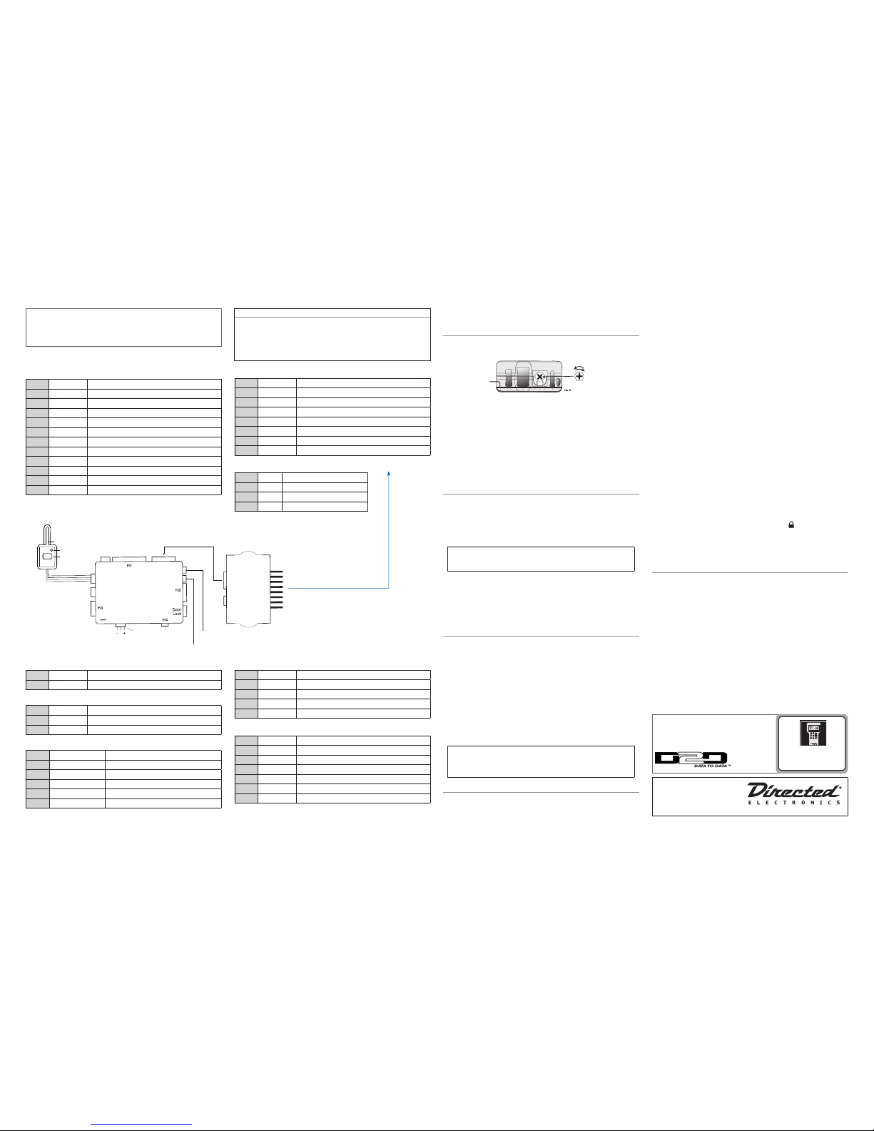
5303
To Remote
Start port
Relay
satellite port
Remote
Start port
H
Bitwriter
D2D port
Control
Center
Button
LED
Shock Sensor port
Jumper
light ash
Antenna
Control Center LED output (use white 2-pin
connector from Control Center cable)
Control Center button input (use blue 2-pin
connector from Control Center cable)
Wiring Connections
Main Harness (H1), 12-pin connector
H1/1
RED/WHITE (-) 200mA AUX TRUNK RELEASE OUTPUT
H1/2
RED (+) CONSTANT POWER INPUT
H1/3
BROWN (+) SIREN OUTPUT
H1/4
NOT USED
H1/5
BLACK (-) CHASSIS GROUND INPUT
H1/6
VIOLET* (+) DOOR TRIGGER INPUT, ZONE 3
H1/7
BLUE (-) INSTANT TRIGGER INPUT, ZONE 1
H1/8
GREEN* (-) DOOR TRIGGER INPUT, ZONE 3
H1/9
BLACK/WHITE (-) 200mA DOMELIGHT SUPERVISION OUTPUT
H1/10
WHITE/BLUE (-) REMOTE START ACTIVATION INPUT
H1/11
WHITE (+)/(-) SELECTABLE LIGHT FLASH OUTPUT
H1/12
ORANGE (-) 500mA GROUND WHEN ARMED OUTPUT
* The door trigger wire will still need to be connected if the system is programmed
with security features OFF to allow the system to enter the programming modes.
Heavy gauge relay satellite
H/1
PURPLE STARTER OUTPUT TO STARTER (STARTER SIDE)
H/2
GREEN STARTER INPUT FROM IGNITION SWITCH (KEY SIDE)
H/3
RED (+) 30A HIGH CURRENT 12V INPUT
H/4
ORANGE OUTPUT TO ACCESSORY CIRCUIT
H/5
RED (+) (30A) HIGH CURRENT 12V INPUT
H/6
PINK OUTPUT TO PRIMARY IGNITION CIRCUIT
H/7
RED/WHITE (+) (30A) HIGH CURRENT 12V INPUT
H/8
PINK/WHITE OUTPUT TO SECOND IGNITION/ACCESSORY CIRCUIT
Relay satellite 4-pin connector
1
BLUE (-) 200mA STATUS OUTPUT
2
ORANGE (-) 200mA ACCESSORY RELAY TURN ON
3
PURPLE (-) 200mA STARTER RELAY TURN ON
4
PINK (-) 200mA IGNITION RELAY TURN ON
H3 Harness Remote Start, 5-pin connector
H3/1
BLACK/WHITE (-) NEUTRAL SAFETY SWITCH INPUT
H3/2
VIOLET/WHITE TACHOMETER INPUT WIRE
H3/3
BROWN (+) BRAKE SHUTDOWN INPUT WIRE
H3/4
GRAY (-) HOOD PIN SWITCH INPUT, ZONE 6
H3/5
BLUE/WHITE (-) 200 mA 2ND STATUS/REAR DEFOGGER - Latched Pulsed
Remote Start ribbon harness*
1
PINK/WHITE (-) 200mA PROGRAMMABLE IGN2/ACC2 RELAY TURN ON
2
YELLOW (+) IGNITION INPUT TO ALARM
3
PINK (-) 200mA IGNITION RELAY TURN ON
4
ORANGE (-) 200mA ACCESSORY RELAY TURN ON
5
PURPLE (-) 200mA STARTER RELAY TURN ON
6
ORANGE/BLACK (-) 500mA ANTI GRIND/GROUND WHEN ARMED OUTPUT
7
BLUE (-) 200 mA STATUS OUTPUT
*The ribbon harness connects to the heavy gauge relay satellite.
H4 AUX 4/Horn, 2-pin connector
H4/1
ORANGE/BLACK (-) 200mA AUX 4 OUTPUT
H4/2
BROWN (-) 200 mA HORN OUTPUT
Door Lock, 3-pin connector
1
BLUE (-) UNLOCK OUTPUT
2
NOT USED
3
GREEN (-) LOCK OUTPUT
H2 Harness, 6-pin connector
H2/1
BLUE (-) 200mA SECOND UNLOCK OUTPUT
H2/2
WHITE/BLACK (-) 200mA AUX 3 OUTPUT
H2/3
VIOLET/BLACK (-) 200mA AUX 2 OUTPUT
H2/4
GREEN/WHITE (-) 200mA FACTORY ALARM REARM OUTPUT
H2/5
GRAY/BLACK (-) WAIT-TO-START INPUT
H2/6
LIGHT GREEN/BLACK (-) 200mA FACTORY ALARM DISARM OUTPUT
Bitwriters with a date code of 6a or older require an IC
upgrade (p/n 998M). Some bitwriters with a date code
of 6B do not require the IC upgrade, refer to tech tip #
1112 for more information.
The Bitwriter® (p/n 998U)
requires chip version 2.7 or
newer to program this unit.
Installation Points
Adjusting the Shock Sensor
Important! Make sure the vehicle is disarmed. The shock sensor sensitivity can be
adjusted by using a trimmer tool to turn the potentiometer.
Adjusting the sensor:
1. Disarm the system, turn the ignition Off.
2. With the sensor mounted in its permanent location, locate the trim pot on the
shock sensor module and using a trimmer tool:
• Turn the potentiometer clockwise for increased sensitivity or
• Turn it counterclockwise for decreased sensitivity
Note: You can test the new setting by cautiously impacting the vehicle with increasing intensity while noting the LED status on the shock sensor. The LED turns
on for a short duration for small impacts before turning off (indicating a warnaway trigger). The impact level required to fully trigger the alarm is indicated
when the LED remains on for a longer duration before turning off.
Tach Learning
To learn the tach signal:
1. Start the vehicle with the key.
2. Within 5 seconds, press and hold the control center button.
3. After 3 seconds the LED will light constant when the tach signal is learned.
4. Release the control center button.
Important: This unit can learn the tachometer with the analog input or
through D2D using an interface module. The unit confirms which source
is used.
When programming tach learning with:
• Analog, the parking lights flash one time
• D2D inerface module, the parking lights flash twice
If the tachometer input on the system is connected to the vehicle, the D2D tachometer
input will be ignored.
Virtual Tach
Note: Virtual tach is not recommended for diesel trucks
To program Virtual Tach:
1. After the install is complete, remote start the car.
2. If the car does not start on the first attempt, let the remote start attempt again.
3. Once the car starts, let it run until the parking lights come on.
4. When the parking lights come on, shut off the remote start with the remote that’s it! Virtual Tach is programmed.
Virtual Tach handles disengaging the starter motor during remote starting – it does
not address over-rev. If the customer wants to have the over-rev protection capability, the tach wire must be connected. This may involve more installation shop
charges than initially quoted.
Important: If the Virtual Tach mode over cranks or doesn't crank the
vehicle long enough to start and run the car, use the Bitwriter to add or
subtract the starter output time. You can adjust the output time in increments of 50msec of the learned time using the Bitwriter.
Reset and Deletion
If a feature/virtual tach needs to be reset or the remote controls need to be deleted,
use the following procedure.
1. Open a door. (The GREEN wire, H1/8, or the VIO LET, H1/6 must be connected.)
2. Turn the ignition to the ON position (The heavy gauge pink wire must be connected).
3. Within 10 seconds, press and release the control center button: 2 times if you
want to delete remotes, 3 times to reset features or 4 times to reset virtual tach.
These features are described next.
Delete remotes: This feature erases all remotes from the memory of the
security system. This is useful in cases when a customer’s remote is lost
or stolen.
Note: This does not reset the programmed features of the security system
or reset the Virtual Tach setting.
Reset Features: This resets all features of the security system to the factory
default settings.
Note: This feature does not delete the remotes from the security system
or reset the Virtual Tach setting or security features enabled/disabled
settings
Virtual Tach Reset: Deletes all previously learned values for Virtual Tach,
and on the next remote start sequence the unit begins virtual tach initialization.
Note: The “Zap” feature on the Bitwriter does not reset the Virtual tach
setting.
4. Once you have selected the function step, press the control center button once
more and hold it. The LED flashes and the siren chirps to confirm the selected
functional step. Do not release the control center button
5. While holding the control center button, press the
button on the remote
control. The unit chirps to confirm that the feature has been successfully reset.
Once the feature is reset, the control center button can be released.
Remote Start Shutdown Diagnostics
To perform shutdown diagnostics:
1. With the ignition Off, press and hold the control center button.
2. Tur n the ignition On and then back Off while holding the control center
button.
3. Release the control center button.
4. Press and release the control center button. The LED flashes to report the last
shutdown for one minute or until the ignition is turned on, as shown in the
following table:
LED Flashes Shutdown Mode
1 flash Timed out
2 flashes Over-rev shutdown
3 flashes Low or no RPM, low battery (voltage and virtual tach modes)
4 flashes Transmitter shutdown (or optional push button)
5 flashes (-) Hood Shutdown (H3/4 GRAY)
6 flashes (+) Shutdown (H3/3 BROWN)
7 flashes (-) Neutral safety shutdown (H3/1 BLACK/WHITE)
8 flashes Wait-to-start timed out
See full Installation Guide for more
detailed information on this system.
Such information and more can be
found online at:
www.directechs.com
Logo, Directed with designed in USA.eps
Guide Translations
For a Spanish version of the Installation Guide, please download it from www.
directechs.com under Resources.
Estimado Cliente:
Si buscas los guías de instalación, por favor de bajar lo del Resources en el sitio
www.directechs.com
Page 2
© 2011 Directed Electronics. All rights Reserved. 2
QRN5303 2011-12
Programming System Features
Note: When doing any programming with security features off, the horn function
(feature menu 1 item 13) must be programmed as Siren function to get an audible
confirmation from the unit.
The System Features Learn Routine dictates how the unit operates. It is possible to
access and change most of the feature settings using the control center button.
1. Open a door.
2. Tur n the ignition on, then off.
3. Select a Menu. Press and hold the control center button. The number of siren
chirps indicates the menu number. 1 chirp indicates menu 1, 2 chirps - menu
2 and 3 chirps for menu 3.
4. When the desired menu chirps are heard, release the control center button.
5. Select a Feature. Press and release the control center button the number of
times corresponding to the feature you wish to change. Then press and hold
one more time to select the features.
6. Program the Feature. While holding the Control center button, you can
program the feature using the remote control.
For features with only two options;
= option 1 while
= option 2.
For features with more than two options;
selects the options in ascending order.
Once a feature is programmed:
• Other features can be programmed within the same menu
• Another menu can be selected
• The learn routine can be exited if programming is complete
To access another feature in the same menu:
1. Press and release the control center button the number of times necessary to
advance from the feature you just programmed to the next one you want to
program.
2. Then press the control center button once more and hold it.
To select another menu:
1. Press and hold the control center button.
2. After 3 seconds, the unit advances to the next menu and the siren chirps, indicating which menu has been accessed.
The learn routine exits if any of the following occurs:
• The open door is closed
• The ignition is turned On
• There is no activity for 30 seconds
• The control center button is pressed too many times
Security Features Disable/Enable
The system has the ability to function as a security/remote start system or keyless/
remote start system by enabling or disabling security. The default setting is Enabled.
To program the feature.
1. Open a door.
2. Turn the ignition on, then off.
3. Press and hold the control center button until the LED flashes 3 times and the
siren (if connected) chirps 3 times.
4. Release the control center button.
Note: If the control center button is released and then pressed again, the system will enter the features programming menus.
5. Within 15 seconds, simultaneously press the
and
buttons of a pro-
grammed remote control.
6. The siren (if connected) will chirp and the parking lights will flash as listed
below
1 flash/chirp: Security features disabled
2 flashes/chirps: Security features enabled
Security Features Disabled will disable all security operations of the system, including but not limited to those listed below:
• Multi Level Arming
• Sensor Warn-away
• Full Trigger Operation
• Armed While Driving
• Automatic Engine Disable
Note: Disabled features with programmable options can still be programmed manually or with the Bitwriter but will not operate until the Security Features have been
enabled.
The Security Features Disable/enable routine exits if the following occurs:
• The open door is closed
• The ignition is turned on
• There is no activity for 15 seconds
• The control center button is pressed too many times
Bitwriter - Only Options
If programming with the Bitwriter®, the learn routine can be locked or unlocked. If the learn routine has previously been locked, it must be unlocked
with Bitwriter® - this cannot be done manually with the control center but-
ton.
The Bitwriter® gives you access to a wider range of system options. These
features and the adjustments that may be programmed are described in the table
below.
Menu
Item
Feature Default Options
1 Siren Duration
30 sec.
1-180 sec.
2 Aux 2 Timed Output
30 sec.
1-90 sec.
3 Aux 3 Timed Output
30 sec.
1-90 sec.
4 Aux 4 Timed Output
30 sec.
1-90 sec.
5 Engine Runtime
12 min.
1-60 min.
6 Diesel Start Delay
15 sec.
1-90 sec.
7 Timer Mode Runtime
12 min.
1-16 min.
8 Virtual Tach Fine Tune
Not initialized
0-1000 in 50 millisecond increments
9 Transmitter Programming
Unlocked
Locked
10 Feature Programming
Unlocked
Locked
Note: The “Zap” feature on the Bitwriter does not reset the Virtual tach or security
features enabled/disabled settings
Red 4-pin port, Bitwriter/ESP2 or D2D programming
The Red 4-pin plug may be configured as a Bitwriter/ESP2 or D2D port.
The factory default is Bitwriter/ESP2 mode.
To use as D2D mode follow the below steps:
1. Make sure White/Blue activation wire is grounded.
2. Power the unit up. The system LED flashes for 5 seconds to confirm D2D mode
change.
3. Remove the White/Blue wire from ground.
To change from D2D to Bitwriter/ESP2 mode:
1. Make sure the White/Blue activation wire is grounded.
2. Power the unit up, the system LED turns on solid for 5 seconds to confirm Bit-
writer/ESP2 mode change.
3. Remove the White/Blue wire from ground.
The procedure can be repeated to toggle from one mode to the other.
Important: If you power up the system with the White/Blue activation
wire ungrounded, the system LED will come on solid for 5 seconds indicating the system is in Bitwriter/ESP2 mode.
Feature Menus
Default settings are in bold type.
Menu 1 - Basic
Menu
Item
One-chirp setting
Two-chirp setting
1
Active Arming
Passive arming
2
Arm/disarm chirps on
Arm/disarm chirps Off
3
Ignition lock On
Ignition lock Off
4
Ignition unlock On
Ignition unlock Off
5
Active locking only
Passive locking
6
Panic with ignition On
No panic with ignition On
7
0.8 second door lock pulses (1)
3.5 (2), 0.4 (3) seconds
8
Forced passive arming on
Forced passive arming off
9
Automatic engine disable on
Automatic engine disable off
10
Armed When Driving (AWD) On
AWD Off
11
Code Hopping On
Code Hopping off
12
Horn Output Pulsed
Constant
13
Horn function Full Alarm Only (1)
Siren function - chirp length
20ms (2), 30ms (3), 40ms (4), 50ms (5)
14
Comfort Closure ON (1)
Comfort Closure OFF (2)
Comfort Closure 2 (3)
Menu 2 - Advanced
Menu
Item
One-chirp setting
Two-chirp setting
1
30 second siren duration
60 second siren duration
2
Nuisance Prevention Circuitry On
Nuisance Prevention Circuitry OFF
3
Progressive door trigger
Instant door trigger
4
Disarm from Valet, 1 pulse
Disarm from Valet, 2-5 pulses
5
Door trigger error chirp ON
Door trigger error chirp OFF
6
Ignition controlled domelight On
Ignition controlled domelight OFF
7
Unlock output 1 pulse
Unlock output 2 pulses
8
Lock output 1 pulse
Lock output 2 pulses
9
Factory disarm with trunk release
ON
Factory disarm with trunk release OFF
10
FAD function with Unlock (1)
Before Unlock (2), Remote Start only (3)
11
FAD 1 pulse
2 pulses
12
AUX 2 validity (1)
Latched (2), Latch reset with ignition
(3), 30-secs timed (4), 60-secs (5),
90-secs (6)
13
AUX 2 Linking None (1)
Arm (2), Disarm (3), Remote Start (4)
14
AUX 3 validity (1)
Latched (2), Latch reset with ignition
(3), 30-sec. timed (4)60sec(5)90sec(6)
15
AUX 3 linking None (1)
Arm (2), Disarm (3), Remote Start (4)
16
AUX 4 validity (1)
Latched (2), Latch reset with ignition (3),
30-sec. timed (4) 60sec (5) 90 (6)
17
AUX 4 linking None (1)
Arm (2).Disarm (3), Remote Start (4)
Menu 3 - Remote start
Menu
Item
One-chirp setting
Two-chirp setting
1
Engine checking: Virtual Tach
Voltage(2), OFF(3), Tachometer(4)
2
Remote start runtime: 12 min
24 min, 60 min
3
Parking light output: Flashing Constant
4
Cranking time: 0.6 sec
0.8, 1.0, 1.2, 1.4, 1.6, 1.8, 2.0, 4.0
second
5
Activation pulse 1
2
6
2nd Ignition/Acc output: Ignition
Accessory
7
Acc state during wait-to-start Off
On
8
2nd status output: Normal
Rear defogger: latch 10 min.
rear defogger pulse
9
Anti grind: On
Off
10
Diesel timer: Wait-to-Start input
Timed 15 , 30 ,45 seconds
11
Timer mode run time: 12 min
3, 6, 9, min
12
Timer mode: Timed starts
Temp starts
13
Short run (turbo): 1 min
3,5, 10 min
Remote Programming
1. Open a door
2. Turn key to the ON position
3. Within 5 seconds, press and release the control center button one time.
4. Within 5 seconds, press and hold the control center button. The LED will flash
one time and the siren chirps to confirm entry into remote programing.
5. Press the
button on the remote control.
6. The siren will chirp to confirm the remote has been programmed.
7. Release the control center button.
8. The siren will emit one long chirp confirming that remote programming has
been exited.
The programming routine exits if any of the following occurs:
The open door is closed
The ignition is turned off
There is no activity for 30 seconds
The control center button is pressed too many times
Basic Remote Functions
Button Function
ARM
DISARM
REMOTE START
AUX TRUNK RELEASE
Note: See Owner’s guide for more details
Long Term Event History
The system stores the last two full triggers in memory. These are not erasable. Each
time the unit sees a full trigger, the older of the two triggers in memory is replaced by
the new trigger. To access long term event history:
1. With the ignition Off, press and hold the control center button.
2. Tur n the ignition On.
3. Release the control center button.
4. Within 5 seconds, press and release the control center button. The LED flashes
in groups indicating the last two zones that triggered the unit for 1 minute or
until the ignition is turned off. Refer to table of zones.
Note: The Warn Away triggers are not stored to memory and is not reported.
Table of Zones
A zone is represented by the number of LED flashes used by the system to identify a
particular type of input.
Zone
Trigger Type
Input Description
1
Instant Trigger BLUE (H1/7)
2
Multiplexed Shock Sensor Input Mux BLUE sensor port wire.
3
Door Trigger GREEN (H1/8) and VIOLET (H1/6).
4
Multiplexed Shock Sensor Input Mux GREEN wire
5
Ignition
Yellow ribbon harness wire
6
Hood Trigger GRAY on the 6-pin shutdown harness
 Loading...